1
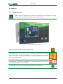
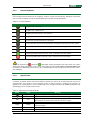
Bay control unit User manual Document version: Update: 05i00 2015-01-22 energetyka.itr.org.pl We reserve the right to modify the device. Tele- and Radio Research Institute ICT and Electronics Centre 03-450 Warsaw, ul. Ratuszowa 11 tel./faks: + 48 22 619 73 14 e-mail: [email protected] www: energetyka.org.pl User manual Contents: 1. General .................................................................................................................................. 4 Designated use ....................................................................................................................... 4 Features ................................................................................................................................. 5 Functionality and accessories ................................................................................................. 8 User interface....................................................................................................................... 10 2.1. Front panel........................................................................................................................... 10 2.1.1. Control keyboard .......................................................................................................... 11 2.1.2. Signal diodes ................................................................................................................ 11 Operation manual ................................................................................................................ 12 3.1. Window ............................................................................................................................... 12 3.2. Menu ................................................................................................................................... 13 3.3. Bay view............................................................................................................................... 14 3.4. Diode description ................................................................................................................. 15 3.5. Event log .............................................................................................................................. 15 3.6. Measurements ..................................................................................................................... 16 3.7. Alarms – cancelling the signaling .......................................................................................... 17 3.8. Control mode ....................................................................................................................... 18 3.8.1. Selection of control mode ............................................................................................. 18 3.8.2. User commands............................................................................................................ 18 3.8.3. Switches ....................................................................................................................... 19 3.9. Management........................................................................................................................ 20 3.9.1. Settings ........................................................................................................................ 20 3.9.2. Supervision................................................................................................................... 23 3.9.3. Configuration ............................................................................................................... 24 3.10. Identification ........................................................................................................................ 26 3.11. Extensions ............................................................................................................................ 26 3.11.1. AI >>> - Autonomous independent overcurrent protection ........................................... 26 3.11.2. DAR – Fault recorder..................................................................................................... 26 3.11.3. CDAR - Criterion recorder ............................................................................................. 27 3.11.4. PQA – Power Quality Analyzer ...................................................................................... 27 3.11.5. SLOG – System Log ....................................................................................................... 27 3.11.6. UPS – Uninterruptible Power Supply ............................................................................. 28 3.11.7. RPS – Redundant Power Supply .................................................................................... 28 3.12. Diagnostic ............................................................................................................................ 28 3.12.1. SC - Self-check .............................................................................................................. 28 3.12.2. MAC - Manual Algorithms Check ................................................................................... 29 3.12.3. CBD - Circuit Breaker Diagnostics .................................................................................. 29 3.13. Autotest ............................................................................................................................... 29 3.13.1. CCT - Cumulated Current Test ....................................................................................... 29 3.13.2. CBCT - Circuit Breaker Control Test ............................................................................... 30 3.13.3. HVT - High Voltage Test ................................................................................................ 30 3.13.4. PAT - Protection and Automation Test .......................................................................... 30 Description of communication interfaces.............................................................................. 31 4.1. Modem RS-485 (2-wire/ 4-wire connection) ......................................................................... 31 4.2. Modem 2 x RS-485 ............................................................................................................... 33 4.3. Twisted Pair RJ Ethernet Modem .......................................................................................... 34 4.4. ST Optical Fibre .................................................................................................................... 34 Remarks of manufacturer ..................................................................................................... 35 5.1. Maintenance, inspections, repairs ........................................................................................ 35 5.2. Storage and transport........................................................................................................... 35 5.3. Place of installation .............................................................................................................. 35 5.4. Disposal................................................................................................................................ 36 5.5. Guarantee ............................................................................................................................ 36 5.6. Service ................................................................................................................................. 36 1.1. 1.2. 1.3. 2. 3. 4. 5. IU_M710P_MANUAL_05i00_ENG Strona 3 z 36 User manual 1. General 1.1. Designated use MUPASZ 710 plus is designated for operation as a multi-function bay control device in MV grids, with grounded or insulated neutral point, and in compensated grids. Fig. 1.1.1 The view of MUPASZ 710 plus. The device can work in grids with frequency 50 or 60 Hz. The MUPASZ 710 plus bay controller may have up to 8 bay types (profiles) implemented which may be freely modified and adapted to the user’s requirements. Logic function simulator is included. The user may also redesign implemented bay views and usage of 16 three-colour signaling diodes. MUPASZ 710 plus works with ELF application used to design individual bay operation logic, parameterization of protections, to configuration, to read measurements and events, and to control device operation in service mode. The regular 36 months warranty period may be extended to 60 or 120 months. Strona 4 z 36 IU_M710P_MANUAL_05i00_ENG User manual 1.2. Features Operation in capacitor battery bay incoming-outgoing feeder generator bay line bay busbar coupling bay measurement bay motor bay transformer bay feeder bay Connector types circuit breaker contactor load switch disconnecting switch disconnecting-earthing switch truck earthing switch short-circuiting switch Control local/remote: user interface, transmission, binary inputs switches: open, close, insertion, withdrawal cancelling: failures AW - TRIP signaling UP - ALARM lock - LOCK binary and analog outputs user commands Automatic functions AACF – Automatic Active Component Forcing ACCB – Automatic Connection of Capacitor Battery CBF - Circuit Breaker Failure AUFLS - Automatic Under Frequency Load Shedding ARF - Automatic Reclosing Function ATC - Automatic Transfer Control Synchrocheck v1 – external synchronizer Synchrocheck v2 - integrated synchronizer BPF - Busbar Protection Function Protections current protection: I>, I>>, I>IDMT, dI>, dI>>, I2f>, I< autonomous current protection: AI>>> zero-sequence overcurrent protection: I0>, I0>IDMT, I0>dir, Y0 > voltage protection: U<, U>, U2>, U0> frequency protection: f>, f<, df/dt motor protection: ItR >, ItA >, ItU >, NfR >, ItS >, U123, Cos φ , Θm> , Rwir < power protection: P>, P<0 technological protection: Tech temperature protection: Temp special protections: Harm, Arc IU_M710P_MANUAL_05i00_ENG Strona 5 z 36 User manual Options of protections operation based on RMS or 1-harmonic directional action operation in CBF mode operation in BPF mode cooperation with ARF voltage stabilization frequency stabilization harmonic stabilization acceleration/deceleration of protection action Measurements current: I1, I2, I3, I0 voltage: U1, U2, U3, U12, U32, U13, U0 frequency: f power: P, Q, S, cos φ energy: EC+, EB+, EC- , EB angle between current signals and voltage signals temperature: Θm (calculated from thermal model), Temp 1…6 (PT100) diagnostics: THD (up to 40 harm), Tp (bay working time), Σ I (cumulated current ) resistance: Rrotor, Rhvt Measurements, set two current: 2.I1, 2.I2, 2.I3 voltage: 2.U1, 2.U2, 2.U3, 2.U12, 2.U32, 2.U13 frequency: 2.f Diagnostic SC - Selfcheck voltage: supply, reference, battery memory: program and data correctness of internal module-to-module communication calibration factors of measurement channels; device set points MAC - Manual Algorithm Check CBD - Circuit Breaker Diagnostics Autotest CCT - Cumulated Current Test CBCT - Circuit Breaker Control Test HVT - High Voltage Test PAT - Protection and Automation Test Extensions AI >>> - Autonomous independent overcurrent protection DAR – Fault recorder CDAR – Criterion recorder PQA – Power Quality Analyzer SLOG – System Log RPS – Redundant Power Supply UPS – Uninterruptible Power Supply Strona 6 z 36 IU_M710P_MANUAL_05i00_ENG User manual User interface three languages: Polish, English, Russian up to 12 users colour display 320 × 240 pixels 7 signal diodes: Emergency trip, Alarm, Lock, Local, Remote, Power supply, Device failure 16 freely configurable tricolour diodes configuration of displayed measurements and event counters bay view editing - over 120 elements of synoptic available: switches, electrical symbols, lines, nodes, texts, measurements, clock, states of binary inputs and outputs, events, messages, signaling operational states Other functions 4 sets of set points event log capacity 1000 events filtering of events displayed system log each defined event has 16 bit counter assigned power outputs (relay-semiconductor type) auto-logging editing selected texts, e.g. names of protections, connectors and signal diodes algorithm operational status registers user registers for free assignment of analog-digital signals IU_M710P_MANUAL_05i00_ENG Strona 7 z 36 User manual 1.3. Functionality and accessories Profile Logic - Used to edit operational logic of the device, utilizes: protections, automatic functions, logic gates, comparators, timers, flip-flops, registers, event blocks, etc. Available via ELF program. Simulator - Used to carry out simulations of designed logic and preview analog-digital signals in the profile schematics. Forcing of input signals and measurement values can be carried out using data saved in COMTRADE format. Available via ELF program. Bay view – Allows editing graphic representation of bay schematics, visible in the device, via ELF program. Freely programmable diodes - 16 freely programmable tricolour diodes. The Elf program allows their editing: assignment of functions to be signaled, signaling order, description, colours and display mode. Set points - Used to preview and edit parameters: nominal values, protections, automatic functions, control and monitoring systems, autodiagnostics; grouped into sets of set points. Texts - Used to preview texts predefined in the device, in supported languages, and to edit editable texts. Available via ELF program. Selected counters - Used to configure Selected Event Counters window. Selected measurements - Used to configure Selected Measurements window. Selected MODBUS records - Used to map MODBUS registers. Monitoring Configuration - Used to preview and edit configuration parameters of the device, i.a. system clock, communication ports, user interface. Log - Used to preview events logged in the device. Event counters - Each event defined in the device has a16-bit counter assigned. Used to preview their values in Event Counter window. States - Used to preview system states, digital inputs and outputs, signal diodes, communication ports, user login information. Measurements - Used to preview measurements, along with their status. UM – User Manager controls and identifies users access to functions of the device. RALG - Algorithm register - used to preview, in textual and graphical form, of algorithm operating states, of e.g. protections, automatic functions, switches. Service - Group of service parameters available to users with service privilege. Strona 8 z 36 IU_M710P_MANUAL_05i00_ENG User manual Extensions AI>>> - Autonomous independent overcurrent protection protects objects against consequences of short-circuits in the absence of device supply voltage. DAR - Fault recorder used to record analog-digital signals with sampling frequency 2 kHz. CDAR - Criterion recorder used to record analog-digital signals with sampling frequency 50 Hz. PQA - Power quality analyzer used to assess the quality of energy at the protected facility. SLOG - System log. Stores time-and-date stamped device operation logs i.a. user logging, last modification of set points, control commands. UPS - Ensures sustaining full functionality of the device for 60 s following voltage decay or up to 200 s with display backlight off. RPS -The solution that allows installation of two independent power supply units in the bay controller, making up redundant power supply system. Diagnostic SC – Self check, monitoring of internal states of the device. MAC – Manual algorithm check simulates measurement values and allows verification of correct operation of an algorithm. CBD - Circuit breaker diagnostics is used to determine critical parameters of circuit breaker/contactor during its operation. Autotest CCT - Cumulated Current Test monitors the value of cumulated current for each phase. CBCT - Circuit Breaker Control Test monitors the integrity of coil control circuits and auxiliary voltage. HVT - High Voltage Test monitors the condition of cable insulation, using high voltage, before energizing the cable. PAT - Protections and Automatic Functions Test verifies correct operation of protections and automatic functions, using external testing systems. Accessories Communication and arc detection fibre optic cables, sealing caps, fixing elements, hardware access key, grounding copper braid, mini USB cable. Accessories available for MUPASZ devices can be found on the website energetyka.itr.org.pl. Availability of individual elements varies by device family and technical specification. IU_M710P_MANUAL_05i00_ENG Strona 9 z 36 User manual 2. User interface 2.1. Front panel The front panel hosts: 320x240 pixel backlit graphic display; control keyboard of the device; LED signal diodes; USB service port for communication with ELF software tool. Fig. 2.1.1 Front panel 1) 2) 3) 4) 5) 6) 7) 8) 9) 10) Freely programmable diodes; diode descriptions on graphic display. Colour graphic 320x240 pixels display. Emergency opening signalization cancelling key - TRIP. Alarm cancelling key - UP . Active circuit breaker lock cancelling key - LOCK. Menu navigation keys. Context keys. Control key – OPEN. Control key – CLOSE. USB mini B service connection port. Strona 10 z 36 IU_M710P_MANUAL_05i00_ENG User manual 2.1.1. Control keyboard Control keyboard of the device has 12 navigation, function, control and context keys. Navigation and context keys are used to navigate around the display MENU and to review and edit parameters. Table 2.1.1 Control keyboard Przycisk Opis navigation key - UP arrow navigation key - DOWN arrow navigation/function key ESC - cancel/return navigation/function key OK - acceptance function key, function description is displayed function key TRIP used to cancel signalization of emergency opening of the main switch function key ALARM used to cancel UP signalization of bay damage function key LOCK used to cancel active locks function key CLOSE used to issue the „close” command to the main switch function key OPEN used to issue the „open” command to the main switch The function keys OPEN and CLOSE allow issuing commands to the main switch. The “open” command is always executable. For the „close” command to be executed the Local or Local and remote mode must be active. Additionally, access to the „close” command may be restricted for some users (see Part 3.9.2.1 User Manager). 2.1.2. Signal diodes In addition to graphic display and control keyboard, device front panel has 23 signal LEDs, 16 of them are programmable. They signal the most important states of device operation, resulting from operation of algorithms, or existing situation, such as establishing a lock, emergency CB opening, ALARM signalization (UPbay damage), local or remote control mode. Table 2.1.2 Meanings of predefined diodes Diode Color green Meaning Signals feeding of correct supply voltage to the device Continuous light. red Signals action of SC Self Check mechanism. Continuous light. Signals opening of the CB caused by tripping of protection set to disconnection or disconnection with lock. Continuous light. Signals protection tripping the signalization. Flashing/continuous light. Signals that the device is locked following activation of any lock. Continuous light. Signals the possibility of local control. Continuous light. Signals the possibility of remote control. Continuous light. TRIP red ALARM yellow LOCK yellow L R yellow yellow IU_M710P_MANUAL_05i00_ENG Strona 11 z 36 User manual 3. Operation manual The below show views may differ for different device specification. 3.1. Window Fig. 3.1.1 Main window In the main window of fig 3.1.1 there are presented elements shown in most user interface windows. 1) The upper line contains the window caption. i.e. the name of relevant branch or window the user is watching at. 2) On the right hand side of the caption icons are located which inform about alarms, locks and emergency CB opening. 3) Position of the cursor (line number) or number of the screen (e.g. in the Log) is located between the header line and the scrollbar. 4) In the lower line functions of the context keys are displayed. 5) The central part of the display is used for presenting numbers, texts or graphic. Strona 12 z 36 IU_M710P_MANUAL_05i00_ENG User manual 3.2. Menu The , and , keys are used to navigate around the device menu. In order to reach destination one should navigate using the , keys. The key is used to accept entering the selected branch. The key allows moving one level up in the menu tree. For quick moving to selected windows or branches the context keys are used. Their current meaning id displayed in the bottom line. For example in order to move from the main window to the Logging window the following path should be followed: Menu > Management > Monitoring > Logging or to use the Logging context key. The context key in the main window are used for: the left one – moving to the user Logging window, the Middle one - moving to the parameter Configuration window, the right one - moving to the Bay view window. The right hand side context key is used for navigating through all widows listed in the main menu starting from the Bay view window and ending in the Identification window. IU_M710P_MANUAL_05i00_ENG Strona 13 z 36 User manual 3.3. Bay view Menu > Bay view Bay view ELF software tool allows configuration of the bay view, customized to user’s needs. There is no need therefore to visualize the whole bay, only its individual components, such as state of the CB. Bear in mind, however, that inserting in the bay view of e.g. earthing switch that is not there in the actual bay, shall result in displaying it as not monitored. Control activates the mechanism of switch control. Activation of this option marks the main switch. Another switch may be selected with the , keys. The switches which cannot be controlled may not be selected and marked. After selection of the required switch and pressing the key the Control window opens in which required switching operations may be selected from the list and confirmed with the key. After selection of the required operation it will be executed or “not available” message displayed. The switches may be operated also in the Switches window or by means of a User command. Strona 14 z 36 IU_M710P_MANUAL_05i00_ENG User manual 3.4. Diode description Menu > Diode description Diode description Device MUPASZ 710 plus is fitted out with the set of freely programmable signal LEDs installed on device front panel. Diodes are configured by means of ELF program, in the tab Logic; configuration consists in assigning a signal from the system, algorithm or automatic function to specific LED. Active state of the signal results in illumination of LED. Descriptions of signalization diodes are defined by editing the text assigned to given diode and are shown on the display. The mark in front of the description text corresponds with the diode colour illumination. LED 1-8/9-16 – allows moving to the widow with descriptions of the other diodes. 3.5. Event log Menu > Event log Event log The Event log holds events generated in the device and allows their viewing. Any recorded event is characterized by: 1) type – see table below, 2) date and time – the events are tagged with 1 ms resolution time tags, 3) descriptive text – displayed in one or two lines, 4) up to 5 parameters, e.g. current value at protection stripping (the parameters may be accessed by selecting the Details context key) The logged events may be filtered for displaying in regard of their types. Having selected the Filter context key a window opens in which event types to be displayed may be selected. By means of the Select context key required positions may be selected or deselected. After confirmation your choice with the key and returning to the Event log window only the event types selected in the Filter window will be displayed. IU_M710P_MANUAL_05i00_ENG Strona 15 z 36 User manual Table 3.5.1 Event types Symbol Event type Normal Activation Alarm Release Tripping Lock Executed Description Standard event type, such as user login. Activation of an algorithm, e.g. protection Execution of algorithm, e.g. protection set to UP signalization - “UP signalization” item selected in Options Deactivation of an algorithm, e.g. protection Execution of algorithm, e.g. protection set to opening of the main switch “Tripping” selected in Options Execution of an algorithm, e.g. protection set to lock - “Lock” or “Temporary lock” selected in Options Execution of an algorithm, e.g. protection 3.6. Measurements Menu > Measurements Measurements The resource stores and provides access to all measurements carried out by the device. Measurements have flags assigned to them that represent their state and validity status (see table below). By pressing the All / Selected keys either all available or only user selected measurements will be displayed. Pressing the Clearing key opens the window for clearing counters, e.g. work time or energy counters. Configuration of Selected measurements is also possible via the ELF software tool. Strona 16 z 36 IU_M710P_MANUAL_05i00_ENG User manual Table 3.6.1 Flags of measurements Symbol Flags of measurements Infinity Description Only used with measurements of resistance. Means opening in measured circuit. Above the range Measured value exceeds upper measuring limit Not available No measurement, e.g. no measurement channel Below the range Measured value exceeds lower measuring limit Unsure Measurement value is calculated basing on incomplete information, e.g. the power is calculated for two phase currents 3.7. Alarms – cancelling the signaling Menu > Alarms Alarms MUPASZ 710 plus implements a series of switch bay protection algorithms. In order to facilitate reading of operating state of algorithms, the software of MUPASZ 710plus device is fitted with the function of displaying aggregated information on states of all algorithms implemented in the active profile. In the Alarms window aggregated information on alarms, locks and tripping is displayed. The DELETE key deletes all signaling and displays a relevant message. If the cause of signaling is still active it will not be cancelled. First the cause should be removed and then the signaling cancelled. Signaling may be selectively cancelled by means of the , , key. An adequate User command on the logic scheme may be used to cancel signalization after adaptation. IU_M710P_MANUAL_05i00_ENG Strona 17 z 36 User manual 3.8. Control mode 3.8.1. Selection of control mode Menu > Control > Selection of control One of four control modes may be selected in the Selection of control window: Local – via device interface, Remote – via communication system, Local and remote – via device interface / communication system, Autonomous control – control without participation of the device (CB is controlled by external devices). See chapter 3.9.1.1 Edition of parameters. Before setting the control mode one should check if the intended mode is allowed in settings. - Menu > Management > Settings > Settings X > Control group > Selection of control. If in the bay operation logic scheme the control mode selection is done via binary inputs then selection of the control mode via the user interface is disabled. 3.8.2. User commands Menu > Control > User commands ELF software tool allows the user to define own commands which activate logic functions from the device menu level. Commands are configured by means of ELF program, in the tab Logic; configuration consists in entering the CMD_USER block and connecting its output signal to the block of the function it is to activate. Selecting the command from device menu shall activate the instruction resulting from the logic. User commands may be used to control the switches, cancel signaling, activation of algorithms or execution of any user designed function present on the device logic scheme. Strona 18 z 36 IU_M710P_MANUAL_05i00_ENG User manual 3.8.3. Switches Menu > Control > Switches In this window all switches included in the device active profile and their states are displayed. After selection of a particular switch and pressing the key the Control window opens. In case the selected switch is not intended for control via the interface the message Lack of control is displayed. If the selected operation is allowable it will be executed and the Switches window will return. Additionally, a relevant event will be logged in the Event log. In order for the operation selected from the Switches submenu to be executed the control mode Local or Local and remote must be selected. IU_M710P_MANUAL_05i00_ENG Strona 19 z 36 User manual 3.9. Management 3.9.1. Settings Menu > Control > Settings The Settings submenu allows selecting active bay type (profile), active set of settings and reviewing and editing parameters in one of four sets of settings. Settings may be modified by a user with adequate level of privileges (see chapter 3.9.2.1. User Manager). Modified parameters are memorized in the set of settings being edited. Menus of all sets of settings for a given profile are identical. Algorithms of protections and automatic functions, control and monitoring functions and nominal values are grouped in separate menu branches. After pressing the Factory context key all parameters in a given set of settings may be restored to factory values. The Cancel command opens again the window with configuration of settings in the edited set. The Factory command will be executed or information displayed that the command cannot be executed. Additionally, a relevant event will be logged in the Event log. Strona 20 z 36 IU_M710P_MANUAL_05i00_ENG User manual An exemplary window with current protections implemented in device profile being edited contains: Two instances of I > One instance of I >> One instance of I > IDMT One instance of EFD > One instance of I < If more than one instance of a given algorithm may be implemented in the device than the number of the instance is displayed in round brackets. An exemplary window with the I > IDMT (1). Parameters, depending on their type, are edited as in the examples below. Options and Active events are multilist type, Direction and Characteristic are monolist type; Ir and T are number type. When starting edition of settings one should first set the nominal values (Bay settings > Nominals) because their values may influence the way the protections and automatic functions operate and their operating ranges. 3.9.1.1. Edition of parameters Below a method of editing monolists, multilists and numbers is presented for an exemplary protection I > IDMT (1). Edition of a MULTILIST parameter consists in selecting any combination of elements from the list The name of the edited parameter is displayed in the window header line. Elements of the list and the selection symbols are displayed underneath: not selected element, selected element. Edition of the multilist is carried out by means of the following keys: , - change of element, Select – element select or deselect, - confirms edited value, - results in leaving the window without saving changes. IU_M710P_MANUAL_05i00_ENG Strona 21 z 36 User manual Edition of a MULTILIST parameter consists in selecting single element from the list The name of the edited parameter is displayed in the window header line. Elements of the list and the selection symbols are displayed underneath: not selected element, selected element. Edition of the monolist is carried out by means of the following keys: , - change of element, Select – element select, - confirms edited value, - results in leaving the window without saving changes. Edition of a NUMBER parameter consists in entering the number in accordance with the format and within allowable range The name of the edited parameter is displayed in the window header line. Allowable range of the parameter (min, max) is displayed below. Edition of number is carried out by means of the following keys: , - increment or decrement one digit, <, > - position change, - confirms edited value - results in leaving the window without saving changes. Changed parameters are displayed in red. Save – used for storing all protection parameters. After its pressing a „write” message appears. Pressing the key results in leaving the I > IDMT (1) window without memorizing the edited parameters. Strona 22 z 36 IU_M710P_MANUAL_05i00_ENG User manual 3.9.2. 3.9.2.1. Supervision User manager (UM) Menu >Management> Supervision > Users The application controls and identifies access by 14 users to device functions, e.g.: changing set points, editing configuration parameters, controlling switches, operating fault recorder, etc. Currently logged-in user is displayed In red. The device Has 5 access levels with different user privileges. User not logged in 10 users to be defined Administrator Service Producer Return – opens the window in which lately used Logging in was Producer and Service users have privileges allowing servicing of the devices; these privileges are not granted to the operating personnel. Activation of the Auto login function results in keeping the latest logged-in user in memory and thus the user is not changed after device restart. If the Autologging function is not active the user is logged in for Password activity time [h:m], after that time automatic logging out takes place (switching to User not logged in). Administrator may grant privileges (see figure) to defined users (also to not logged-in user). User may be defined in the User manager window by granting him a password. This operation results in adding the new user to the list in the Users window. IU_M710P_MANUAL_05i00_ENG Strona 23 z 36 User manual Each user may log in by entering a 4-digit password defined by the Administrator. The password is entered by means of the , , < and > keys (in the same way as the NUMBER parameter). In order to log in the correct password must be entered and the key pressed. Factory password of the Administrator: 1111 3.9.2.2. Digital inputs and outputs Menu > Control >Supervision> Digital Inputs/outputs In this window current states of device binary inputs and outputs are displayed. High state of input/output is marked with the █ symbol, low state with the _ symbol. 3.9.3. Configuration 3.9.3.1. Communication Menu > Management > Configuration > Communication Window is used for configuration of transmission parameters for particular Communications ports. Configuration parameters displayed in the window depend on transmission protocol available for the given COM port. Particular parameters are edited in accordance with their type, as in the edition examples. See chapter 3.9.1.1 Edition of parameters. Strona 24 z 36 IU_M710P_MANUAL_05i00_ENG User manual 3.9.3.2. Interfejs użytkownika Menu > Management > Configuration > User interface User interface menu branch allows modification of the device menu appearance, selection of language and setting display blanking time. Particular parameters are edited in accordance with their type, as in the edition examples. See chapter 3.9.1.1 Edition of parameters. 3.9.3.3. Date and time Menu > Management > Configuration > Clock Menu > Management > Configuration > Clock options After entering the Clock window in the first line current date and time is displayed, and in the second line date and time to edit. See chapter 3.9.1.1 Edition of parameters Confirmation of date and time results in automatic zeroing of milliseconds. In the Clock options window Automatic time change option may be activated (it results in automatic change between standard and summer time). The second option allows to log time change event in the Event log. IU_M710P_MANUAL_05i00_ENG Strona 25 z 36 User manual 3.10. Identification Menu > Identification In the exemplary Identification window there are displayed all parameters identifying device hardware and software: name – MUPASZ 710 plus, serial number - 35 software version – S_M710P_A0_01. In succeeding windows aggregated information relating bay state is displayed, such as main switch state, control mode, active set of settings and address data. 3.11. Extensions 3.11.1. AI >>> - Autonomous independent overcurrent protection Menu > Management > Settings > Settings X > Current > AI >>> AI >>> is an independent circuit for „protection of objects against current faults when the protective device is not powered". Energy for powering the circuit is harvested from the current transformers. AI >>> cooperates with low voltage CB trip coils, what ensures CB opening even when no auxiliary supply is available in the switchgear. Breaking current is also monitored and in case the maximum allowable local switch breaking current is exceeded the open command is issued to the CB in the upper switchgear. More information in IU_M710P_ALGORITHMS_XXiXX. 3.11.2. DAR – Fault recorder Menu > Management > Extensions > DAR – Fault recorder The fault recorder application is used to record analog and digital signals with sampling frequency 2 kHz. The user can configure the number of registered signals, recording time before triggering, cause of the start of recording (binary inputs, binary outputs, digital signals from algorithms or programmable logic and increasing or decreasing values of analog signals). The DAR - Fault recorder window allows the user to manage the work of a recorder. In particular it allows to trigger the recorder from the user interface. For details, refer to the “Fault Recorder User Manual”. Strona 26 z 36 IU_M710P_MANUAL_05i00_ENG User manual 3.11.3. CDAR - Criterion recorder Menu > Management > Extensions > CDAR – Criterion recorder The criterion recorder application is used to record slowly changing signals in the protected object, e.g. motor start-up sequence. It saves analog values (RMS) and digital signals with sampling frequency 50 Hz. The user can configure the number of registered signals, recording time before triggering, cause of the start of recording (binary inputs, binary outputs, digital signals from algorithms or programmable logic and increasing or decreasing values of analog signals). The window Criterion recorder allows the user to manage the work of a recorder. In particular it allows to trigger the criterion recorder from the user interface. For details, refer to the “Criterion Recorder User Manual”. 3.11.4. PQA – Power Quality Analyzer Menu > Management > Extensions > PQA – Power Quality Analyzer The application is intended for energy quality analysis in the object that is being protected according to PN EN 50160:2002, PN EN 61000-4-7 and PN EN 61000-4-30 standards. It provides the THD value and the harmonic content (up to the 40th) of phase voltages and currents. The THD and harmonic content values are used in harmonic protections, that enable selective localization of faults, e.g. bearings damage in motor drives, increase in transformer core magnetization. The PQA – Power Quality Analyzer window displays the averaged values, harmonic content and THD coefficient. 3.11.5. SLOG – System Log Menu > Management > Extensions > SLOG - System Log System log stores information with date and time stamp, referring to logins of individual users, last change in set points, last cancelling of signalization, changes in profiles, bay view, parameters of communication ports, user commands. The log is accessible via SCADA system and ELF software tool. IU_M710P_MANUAL_05i00_ENG Strona 27 z 36 User manual 3.11.6. UPS – Uninterruptible Power Supply The UPS system will maintain the full functionality of the device for 60 seconds after power failure or 200 seconds when the display backlight is turned off. The most common use of these system is in devices which are away from the position of dispatcher, in tight spaces or in hazardous areas. The system is used very often in facilities that do not have a guaranteed supply. It immunizes the device from short power outages which allows to keep continuity of information about the state of the power facility. In case of a power failure, the device, for the guaranteed time, can perform switching operations and send complete information about the state of the bay to the SCADA system, which significantly speeds up the analysis of the situation. The system reaches full capacity after 10 minutes of charging. 3.11.7. RPS – Redundant Power Supply RPS solution consists of two independent power supplies. The default power supply for the controller is power supply No. 1. Make-before-break switching to the power supply No. 2 follows after detection of too low supply voltage by the power supply No. 1. Information about switching to the power supply No. 2 is logged in the Event Log. The redundant power supply is essential for important facilities where reliable operation is paramount. 3.12. Diagnostic 3.12.1. SC - Self-check Subject to self-check are: voltages (supply, reference, battery), memory (program and data), correctness of internal module-to-module communication, calibration factors of measurement channels and device set points. Following detection of damage that could pose threat to safe operation of the switchgear, device operation is stopped, AL relay contacts are opened, optical signalization on the front panel is activated. Such a state requires servicing. Strona 28 z 36 IU_M710P_MANUAL_05i00_ENG User manual 3.12.2. MAC - Manual Algorithms Check Menu > Management > Diagnostics > MAC – Manual Algorithms Check MAC – Manual Algorithm Check window allows to check the correctness of algorithm operation, using simulated measurement values. Execution of specified algorithm test consists of programming selected analog values, needed to assess the correctness of algorithm, forcing the test and analysis of the records in the event log. After test start, analog values are transferred to the algorithms, which results in generation of algorithms response in accordance with protection configuration (tripping, signaling, lock, event recording). Validation of the test result is user’s responsibility. 3.12.3. CBD - Circuit Breaker Diagnostics Menu > Management > Diagnostics > CBD – Circuit breaker diagnostics The CBD – Circuit breaker diagnostics determines the circuit breaker parameters during normal exploitation without disconnecting it from the network. Basing on the acquired information the comprehensive breaker diagnostics is carried out including its wear and possible future malfunction. The CB state report is available through the communication channels and user interface. Items analyzed: CB opening events number irrespective of the cause and value of current in the disconnecting circuit, CB opening events number caused by the over current protection, mean opening time from the last 10 opening cycles, maximal opening time. 3.13. Autotest 3.13.1. CCT - Cumulated Current Test Menu > Management > Diagnostics > CCT – Cumulated Current Test CCT – Cumulated Current Test is a mechanism monitoring the value of cumulated current for each phase. Monitoring consists in adding measured each breaking current to the sum of the former ones. Breaker state report is available via communication ports and user interface. In case the sum of breaking currents exceeds a warning level indicating that the CB wear may cause a failure a warning is generated to carry out service inspection or its replacement. IU_M710P_MANUAL_05i00_ENG Strona 29 z 36 User manual 3.13.2. CBCT - Circuit Breaker Control Test Menu > Management > Diagnostics > CBCT – Circuit Breaker Control Test CBCT - Circuit Breaker Continuity Test checks the continuity of the control lines of the breaker coils and auxiliary voltage. Lack of continuity is indicated by a message on the LCD display, the LED diode and the relay UP output (memorized signalization). Signaling can be reset by pressing UP button on the operator panel. The CBCT can be blocked in the device settings independently for opening and closing circuits. 3.13.3. HVT - High Voltage Test Menu > Management > Settings > Settings X >Autotest > HVT HVT – High Voltage Test checks the cable insulation using external high voltage generator. It allows testing cable insulation and verify the operation of the generator using an external test resistor. HVT can work in manual and automatic modes. In the manual mode, the test is triggered by operator request. In the automatic mode, it is possible to test the generator at the request of the operator, and the test runs automatically before each closing of the circuit breaker. 3.13.4. PAT - Protection and Automation Test Menu > Management > Settings > Settings X >Autotest > PAT PAT – Protections and Automation Test check operation of the protections and the automatic functions using external testers. It allows to check protections and automatic functions including inputs circuits (measuring and digital inputs) used by the algorithm. PAT requires the test signal generators that are attached to the inputs of the bay controller. After the start, test signals are attached to inputs and PAT checks the response to the signals. PAT can work in manual and automatic modes. In the manual mode test are initiated by an operator while in the automatic mode tests run periodically at preset hours. Strona 30 z 36 IU_M710P_MANUAL_05i00_ENG User manual 4. Description of communication interfaces MUPASZ 710 plus may be fitted with the following interfaces: ST type optical fibre, RS-485 / 422 (two- or four-wire), 2 x RS-485 (two- wire), RJ45 Ethernet (twisted pair). These interfaces are used to transfer data (in accordance with selected transmission protocol) Depending on the transmission protocol, the data sent may contain the following information: states of switches in the bay, measurements, event log, counters, states of binary inputs and outputs and may allow to: control the switches, issue signaling cancel commands, modify device configuration, modify set points of protection and automatic functions, activate device functions, transfer inter-bay lock messages, synchronize internal clocks with system clock, transmit content of recorders, reprogramming of the device. Each version of the device is accompanied by documentation which allows to design visualization and to control objects in the power system. 4.1. Modem RS-485 (2-wire/ 4-wire connection) Depending on the connection point of the device within the network, following types of connections are used: Type I – intermediate position – without RT resistor matching wave impedance of the line; Type II – extreme position – with RT resistor matching wave impedance of the line. Above connection types are implemented in the by means of suitable wiring of 10-pin WAGO type 734-110 connector. Depending on device position in RS-485 network, following types of wiring of communication ports are used: Type I (2-wire) Fig. 4.1.1. Intermediate position of the device in 2-wire communication network IU_M710P_MANUAL_05i00_ENG Strona 31 z 36 User manual Type II (2-wire) Fig. 4.1.2. Extreme position of the device in 2-wire communication network It is also possible to connect devices to 4-wire RS-485 communication network. In this case pins 2, 3, 4 of WAGO connector refer to direction of data transmission, pins 5, 6, 7 direction of data reception by the device. Recommendations concerning wiring method for communication ports of devices installed at various locations of communication network, are the same as for 2-wire version. Type I (4-wire) Fig. 4.1.3. Intermediate position of the device in 4-wire communication network Type II (4-wire) Fig. 4.1.4. Extreme position of the device in 4-wire communication network It is recommended that shielded twisted pair is used, with characteristic impedance 120 and low wire-towire capacity, with additional wire equalizing potentials of individual transmission modules. One end of shielding wire should be connected with protective potential of the system. Strona 32 z 36 IU_M710P_MANUAL_05i00_ENG User manual 4.2. Modem 2 x RS-485 Depending on device position in RS-485 network, following types of wiring of communication ports are used: Type I (2-wire) Fig. 4.2.1. Intermediate position of the device in 2-wire communication network Type II (2-wire) Fig. 4.2.2. Extreme position of the device in 2-wire communication network It is recommended that shielded twisted pair is used, with characteristic impedance 120 and low wire-towire capacity, with additional wire equalizing potentials of individual transmission modules. One end of shielding wire should be connected with protective potential of the system. IU_M710P_MANUAL_05i00_ENG Strona 33 z 36 User manual 4.3. Twisted Pair RJ Ethernet Modem The device may be fitted with an optional Ethernet module with MODBUS-TCP and IEC 61850 protocols. Fig.4.3.1. RJ-45 female connector. 4.4. ST Optical Fibre Connection of optical signals consists in plugging ST plugs in relevant sockets paying particular attention to proper matching Tx and Rx transmission directions. During transportation and when cables are not connected optical sockets should be protected with sealing caps. If the optical sockets get dirty or covered with dust they should be cleaned with compressed air before connecting ST plugs. Name Tx Rx Function Optical signal transmit output (to the Rx socket in the cooperating device) Optical signal receive input (to the Tx socket in the cooperating device) Fig.4.4.1. ST fibre optic connector desription. Strona 34 z 36 IU_M710P_MANUAL_05i00_ENG User manual 5. Remarks of manufacturer 5.1. Maintenance, inspections, repairs The device implements programmed operation of protection, control and automatic functions algorithms, and it was fitted with autotest systems responding to internal damage during device operation. The manufacturer recommends that correctness of device operation is verified: a) each time - during commissioning, b) at least once a year - in mine face installations, c) at least once every 5 years in installations other than front face. The following are subject to periodic inspections (if used): correct operation of measurement channels of phase currents and voltages, earth-fault currents and voltages, at rated values; correct operation of control circuits; correct operation of measurement channels of PT100 temperature sensor; one-point check may be carried out; with an external 100 Ω±0,1% resistor indicated temperature should be 0°C. correct operation of 4...20 mA measurement channels; verification check can be carried out at one point, with preset measuring current, e.g. 10 mA. correct operation of communication channels, in line with the implemented protocol; integrity of device protection earthing. It is recommended that the internal battery is replaced at least once every 10 years. The battery should be replaced by service personnel as indicated by manufacturer. Differences observed during checks, or in measurement readings, or in device operation, should be notified to the service center as indicated by manufacturer. Also inspections resulting from branch regulations should be undertaken. Changes in protections set points during operation do not require verification of their correctness. 5.2. Storage and transport Devices are packed in transport packages and secured against damage during transport and storage. Devices should be stored in transport packages, indoors, in places free from vibrations and direct effects of weather conditions, dry, well ventilated, free from harmful vapors and gases. Ambient air temperature should be between –55°C and +70°C, and relative humidity should not exceed 80%. All shipped devices are attached with complete set of connectors, grounding braid, warranty card and quality certificate. 5.3. Place of installation MUPASZ 710 plus series is designed for erection in switchgears, acc. to drawings in IU_M710P_SPECIFICATION. Length of single cable connected to device sockets cannot exceed 50 m. Connection of MUPASZ 710 plus device earthing pin with metallic section of the switching bay should be executed with WAD_6140 grounding braid, delivered with the device. IU_M710P_MANUAL_05i00_ENG Strona 35 z 36 User manual 5.4. Disposal Devices are made mostly from recyclable materials, or materials that can be processed again or disposed of in environmentally sound manner. Decommissioned devices can be collected for recycling, provided that their condition is that of normal wear and tear. All components that are not recyclable shall be disposed of in environmentally sound manner. 5.5. Guarantee Regular 36-month guarantee period; may be extended to 60 or 120 months. Had the sale been preceded by execution of an Agreement between the Buyer and the Seller, provisions of such Agreement shall apply. Guarantee covers remedying of defects, free of charge, provided that instructions specified in the Warranty Card are adhered to. Detailed guarantee conditions may be found at energetyka.itr.org.pl in the w „Sale Regulations”. The guarantee period is counted from the date of sale. The warranty is extended by a period of residence of the product in the repair. Unauthorized tampering with the product will void the warranty. Warranty does not cover damage resulting from improper use of the product. 5.6. Service Servicing includes: guarantee and after guarantee inspections, assistance in commissioning MUPASZ 710 plus devices or switchgears with MUPASZ 710 plus devices both in the country and abroad, device configuration (if requested by the customer): - algorithms set points, - communication ports, - fault recorder, - criterion fault recorder, training courses covering operating skills and programming of the devices; in the manufacurer’s site in Warsaw, Poland designing logical schemes based on documentation delivered by the customer. The engineers team of Tele and Radio Research Institute, with long professional experience in the field of power protection relays, will answer questions regarding operation of the bay controllers, communication and implemented algorithms. Tele- and Radio Research Institute ICT and Electronics Centre 03-450 Warsaw, ul. Ratuszowa 11 tel./faks: + 48 22 619 73 14 e-mail: [email protected] www: energetyka.org.pl Strona 36 z 36 IU_M710P_MANUAL_05i00_ENG