1
®
ADPRO PRO Series
PIR PIDS — Passive Infrared
Perimeter Intrusion Detection Systems
Planning and
Commissioning
Manual
July, 2012
Doc. 20780_03
ADPRO Passive-Infrared (PIR) PRO Series by Xtralis
Planning and Commissioning Manual
Disclaimer
The content of this document is provided on an "as is" basis. No representation or warranty (either express or implied) is made as to the
completeness, accuracy or reliability of the contents of this document. The manufacturer reserves the right to change designs or
specifications without obligation and without further notice. Except as otherwise provided, all warranties, express or implied, including
without limitation any implied warranties of merchantability and fitness for a particular purpose are expressly excluded.
Intellectual Property and Copyright
This document includes registered and unregistered trademarks. All trademarks displayed are the trademarks of their respective owners.
Your use of this document does not constitute or create a licence or any other right to use the name and/or trademark and/or label. This
document is subject to copyright owned by Xtralis AG ("Xtralis"). You agree not to copy, communicate to the public, adapt, distribute,
transfer, sell, modify or publish any contents of this document without the express prior written consent of Xtralis.
General Warning
This product must only be installed, configured and used strictly in accordance with the General Terms and Conditions, User Manual and
product documents available from Xtralis. All proper health and safety precautions must be taken during the installation, commissioning
and maintenance of the product. The system should not be connected to a power source until all the components have been installed.
Proper safety precautions must be taken during tests and maintenance of the products when these are still connected to the power
source. Failure to do so or tampering with the electronics inside the products can result in an electric shock causing injury or death and
may cause equipment damage. Xtralis is not responsible and cannot be held accountable for any liability that may arise due to improper
use of the equipment and/or failure to take proper precautions. Only persons trained through an Xtralis accredited training course can
install test and maintain the system.
Liability
You agree to install, configure and use the products strictly in accordance with the User Manual and product documents available from
Xtralis.
Xtralis is not liable to you or any other person for incidental, indirect, or consequential loss, expense or damages of any kind including
without limitation, loss of business, loss of profits or loss of data arising out of your use of the products. Without limiting this general
disclaimer the following specific warnings and disclaimers also apply:
Fitness for Purpose
You agree that you have been provided with a reasonable opportunity to appraise the products and have made your own independent
assessment of the fitness or suitability of the products for your purpose. You acknowledge that you have not relied on any oral or written
information, representation or advice given by or on behalf of Xtralis or its representatives.
Total Liability
To the fullest extent permitted by law that any limitation or exclusion cannot apply, the total liability of Xtralis in relation to the products is
limited to:
(i) in the case of services, the cost of having the services supplied again; or
(ii) in the case of goods, the lowest cost of replacing the goods, acquiring equivalent goods or having the goods repaired.
Indemnification
You agree to fully indemnify and hold Xtralis harmless for any claim, cost, demand or damage (including legal costs on a full indemnity
basis) incurred or which may be incurred arising from your use of the products.
Miscellaneous
If any provision outlined above is found to be invalid or unenforceable by a court of law, such invalidity or unenforceability will not affect
the remainder which will continue in full force and effect. All rights not expressly granted are reserved.
Document Conventions
The following typographic conventions are used in this document.
Convention
Description
Bold
Used to denote: emphasis
Used for names of menus, menu options, toolbar buttons
Italics
Used to denote: references to other parts of this document or other documents. Used for the result of an
action
The following abbreviations are used in this document.
Abbreviation
Description
AA
Aperture Angle
CZ
Creep Zone
DR
Detection Rate
ESD
Electrostatic Sensitive Device
FAR
False Alarm Rate
GND
Ground
QSG
Quick Setup Guide
PID
Perimeter Intrusion Detector
Doc. 20780_03
i
Planning and Commissioning Manual
ADPRO Passive-Infrared (PIR) PRO Series by Xtralis
PIDS
Perimeter Intrusion Detection System
PIR
Passive Infrared
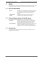
The following icons conventions are used in this document.
Convention
Description
CAUTION!
This icon is used to indicate that there is a danger to equipment. The danger could be loss of data, physical
damage, or permanent corruption of configuration details.
WARNING!
This icon is used to indicate that there is a danger of electric shock. This may lead to death or permanent
injury.
WARNING!
This icon is used to indicate that there is a danger of inhaling dangerous substances. This may lead to
death or permanent injury.
DANGER!
This icon is used to indicate that there is a danger of falling down! There is acute danger, when working with
unsecured ladders. Unsecured ladders can slip and cause a fall that can lead to serious injuries.
Additional information: refer to local „Safety at Work Act“.
NOTE!
This icon is used to highlight useful advice and recommendations as well as information for an efficient and
trouble-free operation.
Tradename statement
ADPRO is a registered trademark of Xtralis AG Pty Ltd.
Contact Us
The Americas +1 781 740 2223 Asia +852 2916 8876 Australia and New Zealand +61 3 9936 7000
UK and Europe +44 1442 242 330 Middle East +962 6 588 5622
www.xtralis.com
ii
Doc. 20780_03
ADPRO Passive-Infrared (PIR) PRO Series by Xtralis
Planning and Commissioning Manual
Contents
1 General.........................................................................................................................................1 1.1 1.2 1.3 2 Information about this Manual.........................................................................................1 Warranty ............................................................................................................................1 Customer Service and Product Monitoring Service ......................................................1 Safety ...........................................................................................................................................2 2.1 2.2 2.3 User’s Responsibility .......................................................................................................2 Personal Requirements and Qualifications ....................................................................2 Intended Use .....................................................................................................................2 3 Description and Introduction .....................................................................................................3 4 Transportation, Packaging and Storage ...................................................................................4 4.1 4.2 5 Planning – Notes .........................................................................................................................5 5.1 5.2 5.3 5.4 5.5 6 Transportation ..................................................................................................................4 Packaging ..........................................................................................................................4 Fundamental Analysis ......................................................................................................5 5.1.1 Perimeter – Definition .............................................................................................5 5.1.2 Applications not Covered........................................................................................6 5.1.3 Performance Capabilities of Perimeter Security Systems ......................................6 5.1.4 Interoperability with other Security and Safety Systems.........................................6 5.1.5 Object Location (Site Position) and Environment – Analysis ..................................7 Planning – Key Points ......................................................................................................9 5.2.1 Nature (Grass, Trees, Animals) ..............................................................................9 5.2.2 Traffic (Vehicles, Equipment, Persons) ..................................................................9 5.2.3 Climatic Conditions (Sun, Wind, Storms, Rain, Hail, Fog) ......................................9 5.2.4 Geographical Position ..........................................................................................11 5.2.5 Special Areas of Application (such as Hazardous Areas) ....................................11 Design and Choice of Detector......................................................................................11 5.3.1 A coherent design raises the cost to the intruder and puts him at greater risk of
discovery ..............................................................................................................11 5.3.2 Saving Time .........................................................................................................12 5.3.3 Advantages of PRO PIR Detectors over other Technology ..................................12 5.3.4 Different Principles for Detectors ..........................................................................13 5.3.5 Barrier or Curtain Detector ...................................................................................13 5.3.6 Surface or Volumetric Detector ............................................................................14 5.3.7 Directional Detection ............................................................................................15 5.3.8 Special Detectors .................................................................................................15 Detector Placement (Typical Design Recommendation).............................................16 5.4.1 Simple Monitoring of an Enclosure with a Simple Boundary ................................16 5.4.2 Monitoring of an enclosure with particularly careful monitoring of the corners .....17 5.4.3 Continuous Monitoring of an Area ........................................................................18 5.4.4 Extensive Monitoring, or Monitoring of Borders, such as of a Country .................19 5.4.5 Monitoring of a Building with Dedicated Camera Surveillance .............................20 False Alarms (according to DIN European Standard 0833-1) .....................................21 5.5.1 Causes of False Alarms .......................................................................................21 5.5.2 No Alarm ..............................................................................................................22 Installation .................................................................................................................................24 6.1 Doc. 20780_03
Detector Installation .......................................................................................................24 6.1.1 Safety Instructions for Installation.........................................................................24 Planning and Commissioning Manual
ADPRO Passive-Infrared (PIR) PRO Series by Xtralis
6.1.2 Wiring .................................................................................................................. 24 6.1.3 Mounting .............................................................................................................. 24 6.1.4 Alignment ............................................................................................................ 26 7 Operating Modes ...................................................................................................................... 28 7.1 8 Commissioning ........................................................................................................................ 30 8.1 9 Walk Test ........................................................................................................................ 30 8.1.1 Walk Test – Hardware Mode ............................................................................... 30 8.1.2 Walk Test – Hardware Operation with CT-PRO Wireless Walk Tester ............... 31 8.1.3 Receiver .............................................................................................................. 31 8.1.4 Transmitter .......................................................................................................... 31 8.1.5 Walk Test – Software Operation .......................................................................... 34 Functions .................................................................................................................................. 36 9.1 9.2 9.3 9.4 9.5 9.6 9.7 9.8 9.9 10 Selectable Operating Modes ......................................................................................... 28 7.1.1 Modes .................................................................................................................. 28 Sensitivity Settings ........................................................................................................ 36 9.1.1 Sensitivity Settings – Hardware Operation (PRO-18(H), 18W(H), 30, 40, 45(H),
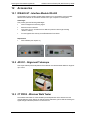
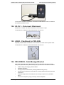
45D(H) only) ........................................................................................................ 36 9.1.2 Sensitivity Settings – Software Operation ........................................................... 36 Adaptive Threshold Discrimination (ATD) ................................................................... 37 Vandalism Protection .................................................................................................... 38 Intelligent Digital Signal Processing ............................................................................ 39 Internal Temperature Compensation ........................................................................... 39 Pulse Count .................................................................................................................... 39 Directional Detection ..................................................................................................... 40 Mounting Height Adjustment ........................................................................................ 40 Internal Heating Device ................................................................................................. 41 Software Installation ................................................................................................................ 42 10.1 System Requirements ................................................................................................... 42 10.2 Install Software .............................................................................................................. 42 10.2.1 Install on Windows 7 Platform ............................................................................. 42 10.2.2 Install on XP Platform .......................................................................................... 45 10.2.3 Configure Communication Port ........................................................................... 48 10.3 Use Software .................................................................................................................. 51 10.3.1 Select Detector .................................................................................................... 53 10.3.2 Select Communication Port ................................................................................. 55 10.3.3 File ....................................................................................................................... 55 10.3.4 Option .................................................................................................................. 55 10.3.5 Scope .................................................................................................................. 62 10.3.6 Tool ..................................................................................................................... 64 10.4 Uninstall Software.......................................................................................................... 70 11 Normal Operation ..................................................................................................................... 71 11.1 Connection Options....................................................................................................... 71 11.1.1 Contacts .............................................................................................................. 71 11.1.2 Permanent Links.................................................................................................. 71 12 Accessories .............................................................................................................................. 72 12.1 IFM-485-ST - Interface Module RS-485 ......................................................................... 72 12.2 AD 851 - Alignment Telescope ..................................................................................... 72 Doc. 20780_03
ADPRO Passive-Infrared (PIR) PRO Series by Xtralis
12.3 12.4 12.5 12.6 13 Planning and Commissioning Manual
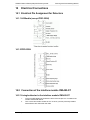
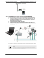
CT PRO2 - Wireless Walk Tester ...................................................................................72 ZA P-L1 – Pole-mount Attachment ................................................................................73 AD653 - Pole-Mount for PRO-250H................................................................................73 PRO-CMB-W - Cable Managed Bracket ........................................................................73 12.6.1 PRO-CMB-S — Tamper-Switch (PRO-CMB-S) ...................................................74 Diagram......................................................................................................................................76 13.1 Terminal – Top view (all models except PRO-250H) ....................................................76 13.2 Terminal – Side view (all models except PRO-250H) ...................................................76 14 Electrical Connections .............................................................................................................77 14.1 Electrical Pin Assignment for Detectors ......................................................................77 14.1.1 All Models (except PRO-250H) ............................................................................77 14.1.2 PRO-250H ............................................................................................................77 14.2 Connection of the interface module IFM-485-ST .........................................................77 14.2.1 A single detector to the interface module IFM-485-ST .........................................77 14.2.2 Several detectors to the interface module IFM-485-ST ........................................78 15 Dimensions................................................................................................................................80 16 Model Specifications ................................................................................................................81 16.1 Volumetric Detectors ......................................................................................................83 16.1.1 ADPRO Passive-IR-Detector PRO-18 and PRO-18H ..........................................83 16.1.2 ADPRO Passive-IR-Detector (PIR) PRO-18W and PRO-18WH ..........................84 16.1.3 ADPRO Passive-IR-Detector (PIR) PRO-30 ........................................................85 16.1.4 ADPRO Passive-IR-Detector (PIR) PRO-40 ........................................................85 16.1.5 ADPRO Passive-IR-Detector (PIR) PRO-51 ........................................................86 16.1.6 ADPRO Passive-IR-Detector (PIR) PRO-85 and PRO-85H .................................87 16.2 Curtain Detectors (Barrier Detectors) ...........................................................................88 16.2.1 ADPRO Passive-IR-Detector (PIR) PRO-45, PRO-45H and PRO-45H-IP65 .......88 16.2.2 ADPRO Passive-IR-Detector (PIR) PRO-45D, PRO-45DH and PRO-45DH-IP6589 16.2.3 ADPRO Passive-IR-Detector (PIR) PRO-100 and PRO-100H .............................89 16.2.4 ADPRO Passive-IR-Detector (PIR) PRO-250H ....................................................90 17 Maintenance and Service .........................................................................................................92 17.1 Safety ...............................................................................................................................92 17.2 Environmental Protection ..............................................................................................92 17.3 Recommendations ..........................................................................................................92 18 Troubleshooting ........................................................................................................................93 18.1 False Alarms ...................................................................................................................93 19 Disassembly and Disposal .......................................................................................................94 19.1 Safety ...............................................................................................................................94 19.2 Environmental Protection ..............................................................................................94 19.3 Measures before Disassembly ......................................................................................94 20 Product Overview .....................................................................................................................95 Doc. 20780_03
ADPRO Passive-Infrared (PIR) PRO Series by Xtralis
1
General
1.1
Information about this Manual
Planning and Commissioning Manual
Use of the Manual
This manual allows the safe and efficient installation and
handling of the device. A prerequisite for proper function of the
device is to comply with all the information and the instructions
in this manual.
Obligation to read
This manual must be read carefully before the installation of the
device.
Images in this
Manual
Images in this manual are provided for basic understanding
only and can vary depending on the version of the device.
Loss of the Manual
In the event of loss of this manual, a replacement can be
ordered from Xtralis. See page ii for contact details.
Information in this
Manual
The information and safety instructions in this manual have
been compiled in accordance with current standards,
guidelines and rules, using the latest technology and they are
based on many years of experience.
The scope of delivery or the performance of the device may
vary depending on optional order items, production of special
versions or the latest technical modifications to the
descriptions and representations given here.
1.2
Warranty
Location
The terms of warranty are set out in the purchase agreement
and the general terms and conditions of the manufacturer.
In Principle
The manufacturer will make the final decision with respect to a
warranty claim relating to the return of any defective parts,
possibly after visiting the site.
The warranty period of the device is not extended through the
replacement of defective parts.
Any changes or major repairs by the user or a third party
without the written consent of the manufacturer will nullify the
warranty.
1.3
Customer Service and Product Monitoring Service
Customer Service
In case of problems and issues that cannot be solved by using
this manual and for technical information, contact our
customer service. See page ii for contact details.
Product Monitoring
With the aim of continuously improving our products, we are
interested in learning about experience gained from using the
device.
We welcome information about experiences in dealing with
device malfunctions during operation.
Please always inform the manufacturer in the event of
accidents or near misses.
Doc. 20780_03
1
Planning and Commissioning Manual
2
ADPRO Passive-Infrared (PIR) PRO Series by Xtralis
Safety
This chapter gives an overview of all important aspects of safe and trouble-free use. Failure
to observe the instructions and warnings in this handbook can lead to injury or death.
2.1
2.2
User’s Responsibility
General
The instructions in this handbook are for the safety of the user
and the prevention of accidents. Environmental regulations
that may apply to the location of the unit must also be
observed.
Perfect technical
condition
To guarantee perfect technical condition the advice on
maintenance in this handbook should be followed.
Personal Requirements and Qualifications
In this handbook the following qualifications for various tasks will be assumed:
2.3
Electricians
Electricians have the training, experience and knowledge of
standards, regulations and procedures that qualify them to
work on electrical systems knowing the relevant risks.
System Integrators
Qualified system integrators have the training, experience and
knowledge of standards, regulations and procedures that
qualify them to work on IT systems knowing the relevant risks.
Intended Use
The unit should not be used in areas where there is a danger of explosions or where
dangerous substances are used.
2
Doc. 20780_03
ADPRO Passive-Infrared (PIR) PRO Series by Xtralis
3
Planning and Commissioning Manual
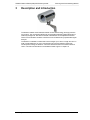
Description and Introduction
The detector enables motion detection based on infra-red technology and high-precision
mirror optics. The unit registers differences in temperature between mobile objects and a
stationary background. The alarm threshold of the detector can be adjusted to external
factors such as ambient conditions. Interference can be filtered out by sophisticated signal
analysis.
The detector is available in models with nominal ranges up to 150 m in length and 30 m in
width. Curtain detectors, for use in narrow areas over long and medium ranges give
uninterrupted coverage of detection. Volumetric detectors monitor the whole of a field of
vision. Full technical information on all available models is given in chapter 16.
Doc. 20780_03
3
Planning and Commissioning Manual
ADPRO Passive-Infrared (PIR) PRO Series by Xtralis
4
Transportation, Packaging and Storage
4.1
Transportation
NOTE!
To avoid damage, the unit should be transported in its original
packaging.
4.2
Packaging
Packaging
The unit is packaged for normal transportation and storage conditions. All the material used
in the packaging is environmentally friendly. The packaging protects the unit from damage in
transit, corrosion and other damage. The packaging should therefore not be destroyed but
simply removed before installation.
Handling of the packaging
If the packaging is no longer needed, it must be disposed of properly in accordance with
applicable laws and local regulations.
WARNING!
Environmental damage can be caused by improper disposal!
Packaging materials are valuable raw materials that can often be
reused or recycled, so dispose of them in an environmentally friendly
way, and comply with local disposal regulations.
Unpackaging
The detector is typically delivered as a standalone product together with a Quick Setup
Guide (QSG); no further documentation is included. Documentation and utilities such as the
latest version of this ADPRO PRO PIR Planning and Commissioning Manual, the ADPRO
PRO PIR data sheets, ADPRO PRO PIR brochures are available for download from the
www.xtralissecurity.com Xtralis Security Solutions Support Site.
Please unpack the detector heeding customary Electrical, Electrostatic Sensitive Device
(ESD) and safety precautions and proper grounding.
CAUTION!
Disassembling the detector can cause permanent damage and will
void the warranty.
Operating the detector outside of the specified input voltage range or
the specified operating temperature range can cause permanent
damage.
A detector contains electrostatic discharge sensitive electronics and
should be handled appropriately.
4
Doc. 20780_03
ADPRO Passive-Infrared (PIR) PRO Series by Xtralis
5
Planning and Commissioning Manual
Planning – Notes
Perimeter (‘peri’, from the Greek for ‘round about’) security measures have been in use for
centuries, if not for millennia. Spears, palisades, walls and moats have all been used as
effective defensive measures.
These generally very effective perimeter security mechanisms were intended not to let
potential attackers get close to the actual physical barriers (such as drawbridges or castle
walls), or at least to make this difficult for them. From very early on, then, measures were
taken and defensive force was used.
Current, modern perimeter security measures differ only in the measures (fences) and
devices (detectors) used from a historical castle moat. Not in the basic principle of a
concept of protection.
In addition to mechanical security systems, a variety of electronic detection and verification
measures are now available. Together with well-planned organisational measures, it is
therefore possible to make a real contribution to protection from unauthorised access, theft,
robbery, burglary and sabotage attacks such as arson.
But such systems can also be used for the protection of life and limb. An example of this
might be a deer crossing warning system which, in conjunction with electronic traffic lights,
prevents accidents. Or a monitoring system for platforms at transit stations, so that no one is
endangered by the suction of air from passing trains.
These non-binding planning notes are intended as a guide for insurance companies,
consultants, specifiers, layout engineers, judges, integrators, and of course users, to show
how through carefully planned perimeter security systems a reduction in risk in anticipation
of any possible threat can be achieved, as part of a wholistic plan for property security.
Because of the diversity and uniqueness of the sites and objects to be secured, and their
individual environments, the following can only go into the fundamentals. Possible solutions
and concepts will be presented by means of typical and commonly occurring cases.
5.1
Fundamental Analysis
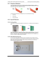
5.1.1 Perimeter – Definition
For the purpose of these planning notes, a perimeter is an environment, generally of a
building, area or an industrial plant (such as oil wells, water tanks, solar power facilities,
transmission masts, logistic or distribution center, car dealer); the borders of this
environment; or focal points within this environment. Extending in the horizontal plane, the
legal boundary of the site is the furthest limit of the perimeter. An inner boundary (which
there necessarily need not be) can be formed by a building, a facility or similar, that is
situated within the range of the legal boundary. External walls of buildings within the
perimeter can also stand for inner boundaries; parts of the interior of buildings can also count
for the perimeter range. The perimeter also has vertical, legal boundaries. Depending on the
risk situation, it may be necessary to have perimeter surveillance in the vertical plane
(extending up or down).
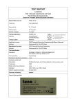
These diagrams show the arrangements of the boundaries.
Doc. 20780_03
5
Planning and Commissioning Manual
ADPRO Passive-Infrared (PIR) PRO Series by Xtralis
Schematic based on “VdS Security Guideline Perimeter VdS3143 (on the authority of VdS, Cologne)”
5.1.2 Applications not Covered
These planning notes describe options that can offer security against hostile outsiders, and
refer to industrial or infrastructure facilities, depending on the risk situation. They do not refer
to the most at-risk facilities such as power stations, including nuclear power stations, military
installations or prisons.
Personal protection measures are not discussed in the course of this policy.
NOTE!
For this, we advise you to call us personally.
5.1.3 Performance Capabilities of Perimeter Security Systems
Because of technology, no perimeter security system can give 100% reliable protection.
Therefore, the operator of the facility must be informed of the performance limits of the
chosen measures.
Since the electronic devices of the perimeter security system are permanently set to the
surrounding environmental conditions, it can sometimes lead to limitations in the
performance capability of the facility if no corresponding countermeasures are taken.
Basically, it can be stated that higher detection sensitivity leads, as a rule, on the one hand
to a very high detection rate (DR), but on the other hand to a high probability of false alarms
with a large false alarm rate (FAR).
One significant value for the quality of perimeter security is the DR/FAR ratio; the closer the
value to 1, the better the quality of the system.
5.1.4 Interoperability with other Security and Safety Systems
Perimeter security systems must be included from the start as part of a comprehensive plan,
to ensure as seamless as possible an interaction of security systems.
If, for instance, intrusion detectors and/or video surveillance cameras are planned or are
already in place, ADPRO detectors can be integrated without difficulty.
6
Doc. 20780_03
ADPRO Passive-Infrared (PIR) PRO Series by Xtralis
Planning and Commissioning Manual
For this purpose, the wiring (number of wires, cable length, cable channels, cable lengths,
interfaces) must match exactly. What information is needed for what system should be
specified.
5.1.5 Object Location (Site Position) and Environment – Analysis
5.1.5.1 Threats – Risk – Scenarios – Probabilities
Many commercial sites and industrial buildings, and related open spaces like distribution
centres and garages with large open spaces, goods and equipment storage areas, or scrap
yards, do not present too great a challenge to potential criminals.
In times of economic crisis, these outlying places present a particular incentive for criminal
enterprises, and can lead to risks if unauthorised and unnoticed access takes place. Due to
the increasing interdependency of modern business processes even small disruptions can
lead to considerable financial damage.
As part of a comprehensive security plan, building security focuses on the protection of the
contents. The use of mechanical perimeter security measures in combination with an
electronic security system is now well known and widely accepted. So a comprehensive
security plan begins right at the boundary of the property.
The concept of comprehensive security must now be analysed in detail.
1.
Threat Analysis
This includes the identification of possible threats and offender profiles, the assessment of
possible damage, and the estimation of the probability of an accident. Owners themselves,
landlords, lenders, police, the fire brigade and future insurers must be included in the
planning.
2.
Threat Scenarios
As part of these planning notes, the following scenarios are conceivable:
Theft of existing goods from the premises
Breaking into buildings
Sabotage or vandalism of operational facilities
Espionage
Arson
NOTE!
Risks to people’s lives and hostage takings are not discussed in these
planning notes.
3.
Offender Profiles
With regard to the previously mentioned threats the following different offender profiles can
be assumed:
Opportunistic Offender
Who seizes an opportunity to gain something as a means of payment, or of value in
itself (drug-related crime), or who commits vandalism, such as spraying graffiti, setting
fires, or sabotage.
4.
Professional Criminal
An individual, or gangs, which are characterised by their targeted approach (such as
the purchase of specialised car parts according to serial number, targeted theft of
recycling, sabotage or espionage).
Offenders’ “qualifications”, or level of performance of a security system,
according to European Standard EN 50131-1
Grade 1: Low Risk
An intruder or robber has little admitted knowledge of the security system; he has a
limited number of readily available tools.
Doc. 20780_03
7
Planning and Commissioning Manual
ADPRO Passive-Infrared (PIR) PRO Series by Xtralis
Grade 2: Low to Medium Risk
An intruder or robber has little admitted knowledge of the security system; he has
generally available tools and portable instruments such as a multimeter.
Grade 3: Medium to High Risk
An intruder or robber has admitted that he is familiar with security systems, and has
an extensive inventory of tools and portable electronic devices.
Grade 4: High Risk
This level is used when security takes priority over all other factors. An intruder or
robber has admitted having the ability to plan a burglary or robbery in detail, and has a
complete kit including the means of substituting one component of a security system
for another.
NOTE!
In these levels, the word ‘intruder’ is used to include all types of threat,
such as robbery or the threat of physical violence, which could affect
the planning of a security system.
5.
Types of attack on a perimeter security system
Walking, running or jumping:
An intruder tries to cross a boundary by walking or running. This usually occurs in
case of systems where there is no barrier or fence.
Climbing:
An intruder tries to get over the system by climbing directly over it. This applies only to
systems with barriers. The areas under surveillance of these systems cannot be
climbed into without assistance. A deferred detection system ‘assumes’ that an
intruder has entered by climbing, but entry might have been effected by cutting.
Cutting:
As with climbing, a barrier is required for this occurrence to be recognised. The
explanation is similar to ‘climbing’. Because of technology, PIR detectors cannot
detect cutting of the perimeter. However, the system can be planned so that
manipulation of fences, and above all subsequent penetration, can be securely
detected. The right choice of detector output is particularly important here.
Ladders:
‘Ladders’ is used here to mean all aids to elevation (such as a tall lorry parked near a
barrier). Two ways of surmounting a barrier with a ladder are to be distinguished:
Use of a ladder that makes contact with a barrier (leaning ladders)
Use of a ladder that makes no contact (a stepladder)
Because of technology, the PIR detector cannot detect the actual surmounting of a
barrier. Nevertheless, a system can be planned so that this type of attack and
subsequent invasions can be safely detected, provided the right detector has been
chosen. Again, careful planning of the system has a significant effect on the detection
of events and the false alarm rate. In contrast to other detection technologies, both
leaning ladders and stepladders are well known as aids to elevation.
Tunneling underground:
It is generally assumed that tunnelling under a barrier can in principle only be detected
by a ground detection system, because these are the only systems installed directly
into the ground. Because of technology, the PIR detector cannot detect tunnelling
under a barrier. But since the intruder has to come up to the surface to accomplish his
purpose, the system can be planned so that this type of attack, and subsequent
passage through the monitored area, can be safely detected. Here, too, the right
choice of detector is particularly important.
Driving through:
This is comparable to walking or running, but it involves greater speed and greater
mass. Because of this higher energy, in contrast to walking or running, a barrier can
be broken down. In some cases, because of technology the PIR detector cannot
8
Doc. 20780_03
ADPRO Passive-Infrared (PIR) PRO Series by Xtralis
Planning and Commissioning Manual
detect a barrier’s being driven through, precisely because of too high a speed. But
since the invader has to come to a standstill to accomplish his purpose, the system
can be planned so that this type of attack, and in particular subsequent passage
through the monitored area, can, again, be safely detected. Here, too, the right choice
of detector, and the number and strategic placement of the detectors, is especially
important.
5.2
Planning – Key Points
5.2.1 Nature (Grass, Trees, Animals)
In planning perimeter monitoring with ADPRO detectors, take note of the following points:
The area to be covered should have no moveable objects such as trees, branches,
shrubs, lawns with long grass, fences or bodies of water.
When you inspect the property, look out for animal holes such as foxholes, badgers’
setts, rabbit warrens, etc., in the vicinity of the barrier. Ask the user of the property
about this.
5.2.2 Traffic (Vehicles, Equipment, Persons)
It must be noted here that the nominal range stated is such that a person or object of height
1.5 m can be detected. This necessarily means monitoring of more than the area to be
covered, so long as it is not artificially limited.
Do not set up one single detector on a wire or metal fence, and especially not beyond
a fence.
In order to avoid false alarms caused by passers-by, the range of coverage should be
limited by a natural or artificial background (such as a wall).
Vehicles, in particular large ones that produce a lot of heat (lorries, tractors,
harvesters, etc.) and other equipment (diesel generators for power systems,
refrigerated containers, etc.) are strong sources of heat. Take care in planning that
such sources of heat are not operating in the range of a detector. If there is a car park
outside the fence, make the operator aware of it. If this is unavoidable, several
connected detectors should be used.
5.2.3 Climatic Conditions (Sun, Wind, Storms, Rain, Hail, Fog)
Depending on the climatic condition, the perimeter monitoring system is, in part, permanently
exposed to extreme environmental conditions. Because of technology PIR detectors can
sometimes perform badly. These natural factors are unavoidable, but with precise planning,
they can be to a large extent compensated for, or even eliminated entirely.
The following points should be noted:
PIR detectors are to be configured so that they are not exposed to heat radiation,
especially that of the sun. Note that the sun can be very low at some seasons.
ADPRO PRO detectors, thanks to a very complex signalling process and subsequent
validation check, offer a modern compensation system. Nevertheless, if a detector
directly faces the rising or setting sun, nuisance alarms can be triggered.
Do not set up a single detector directly on a wire fence, as in a sunny environment this
can cause significant movement in the warm air currents above the barrier.
Check whether prolonged and intense fog is to be expected at the planned site.
Because fog consists of tiny droplets of water in the micrometre range (20-40 µm), the
radiation emitted by a body might only be received dampened by a PIR detector, since
the infrared radiation is reflected and partially absorbed by the droplets of water.
Experience has shown that the distance between individual detectors should be no
greater than 45-50 metres. This makes safe operation with a good detection rate
possible.
Doc. 20780_03
9
Planning and Commissioning Manual
ADPRO Passive-Infrared (PIR) PRO Series by Xtralis
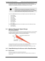
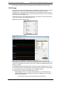
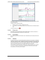
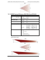
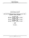
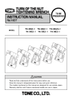
During a walk test in thick fog (see below picture) the alarm went off clearly at a distance of
80 m. The oscilloscope ‘snapshots’ below the picture show the corresponding detector signal
values. Left, the value for 80 m; right, at a distance of a 100 m with the same detector
installed, the alarm threshold was nearly but not quite reached.
10
If the test subject had left a warm building and spent only a few moments in the cold,
fresh air, the alarm would have sounded at a distance of up to 120 m.
Type of detector
: 100H (without heating)
Date and time
: 21 November 2011, 8 a.m.
Location
: Xtralis, south side
Type of ground
: grazed pasture
Height of mounting of detector : 4 m
Visibility
: c. 120 m (thick fog)
Atmospheric pressure
: 1021.3 mb
Humidity
: 94% (light dew, just forming ice)
Air temperature
: -1°C
Ground temperature
: -7° C
Body temperature
: -1° C. (The test subject wore a Gore-Tex (TM)
jacket)
Head temperature
: +19°C
The moisture of rain, hail and snow can affect the detection rate. However, since the
particles that form these are larger in diameter, sufficient radiation can penetrate
between them. Typically, these environmental conditions do not last a very long time.
In coastal areas, and near large lakes, this point of planning should be taken into
special consideration.
Doc. 20780_03
ADPRO Passive-Infrared (PIR) PRO Series by Xtralis
Planning and Commissioning Manual
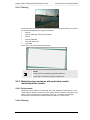
In agricultural environments such as harvested fields, or deserts, there can be strong
winds, leading to drifts of pollen (from cereal crops), leaves (from forests) and
sandstorms. This too must be adequately taken into account when planning. In
particular, the barrier itself must be capable of withstanding these, and the mast for
the PIR detector must be free of torsion and vibration as far as possible. Because of
climate change, even more extreme weather is likely in continental Europe.
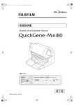
Walk Test in Winter
5.2.4 Geographical Position
The perimeter monitoring system is designed to project according to geographical location.
Installations on level ground are not critical for planning, but if there are structures on uneven
ground, care must be taken in case areas hidden by hills are not monitored; there may be
gaps in the detection area.
Modern tools such as Google Earth and Google Maps can be helpful in analyzing orientation
and environments.
5.2.5 Special Areas of Application (such as Hazardous Areas)
In sensitive areas, planning and execution of a perimeter monitoring system should take into
account any applicable laws, rules and regulations.
We are happy to help you with planning your system on request.
5.3
Design and Choice of Detector
5.3.1 A coherent design raises the cost to the intruder and puts
him at greater risk of discovery
The better the perimeter security is adapted to particular circumstances, the more effort is
required from a perpetrator. This is accompanied by the necessary criminal intent to commit
the deed; add to that the cost in terms of tools, know-how and time of overcoming a security
Doc. 20780_03
11
Planning and Commissioning Manual
ADPRO Passive-Infrared (PIR) PRO Series by Xtralis
system. The greater the expenditure, in terms of time and in other ways, the more likely it
becomes, as a rule, that the perpetrator will be discovered.
5.3.2 Saving Time
Three periods of time are important as part of an effective perimeter security system:
Time until the alarm
Time needed to overcome perimeter security
Time from the alarm to intervention, either on the protected object, or directly at the
scene of the crime
Clearly, having an alarm at an outer boundary, rather than at the protected object itself,
saves a lot of time. When a detector has as high a detection rate as possible, whilst at the
same time avoiding false alarms, it enables the alarm to be swiftly verified, and confers an
advantage in terms of time. The time between the alarm, and the alarm sounding or ‘alert’,
becomes short. ‘Intervention time’ is the time it takes for assistance to reach the protected
object from the alarm. The intervention time can vary according to place, time, or other
circumstances. High levels of traffic, an increase in the frequency of extreme weather
conditions, and so on, can lead to a significant increase in intervention time. This time must
be taken into account when planning perimeter security. Precise local information about
points of entry leads to more efficient and effective intervention.
5.3.3 Advantages of PRO PIR Detectors over other Technology
ADPRO PRO PIR detectors are a versatile solution for a variety of terrains and surfaces –
whether asphalt, plaster, gravel, grass, flower beds or even roofs. PIR detectors also offer a
very good price-performance ratio in relation to monitored areas.
12
Volumetric ADPRO PRO PIR detectors cover large spaces.
Long distance detectors, on the other hand, cover a narrow range, and can also detect
objects at great distances.
The most common uses for PIR detectors are in perimeter and exterior protection.
However, the detectors can also be used for interior monitoring, for instance in large
factories.
The preparations that have to be made on the property itself are small in relation to
the area to be protected, as in most cases foundations for fences already there can be
used to put up masts.
Doc. 20780_03
ADPRO Passive-Infrared (PIR) PRO Series by Xtralis
Planning and Commissioning Manual
Operating and maintenance costs are comparatively low, because when a system is
properly planned and operated it needs very little maintenance.
Any seasonal adjustments or changes to use can easily be configured from a
distance, if a detector is, for instance, connected to an ADPRO video gateway via a
communications bus.
The camera body, modelled on a plastic housing, accords with protection standard IP
54, and optionally IP65 or even IP66.
The metal bracket to hold the detector, and all screws, are made of weather-resistant
stainless steel.
The PIR detector housing, and the plastic gas chamber (including terminal) that will
shortly become available, with its tamper-proof, concealed cable guide (‘cable
management’) are UV-stable and impact-resistant.
5.3.4 Different Principles for Detectors
Basically, detectors can be distinguished according to two main principles:
Barrier or curtain detectors
Surface or volumetric detectors
But to give a more precise solution for the requirements of different objects, there are finer
gradations between:
Curtain detectors with a larger aperture angle and medium nominal range
Curtain detectors with a small aperture angle and large nominal range
Volumetric detectors with a wide aperture angle and short nominal range
Volumetric detectors with a very wide aperture angle and medium nominal range
Volumetric detectors with a wide aperture angle large nominal range
Details of the nominal ranges, monitoring angles of aperture, and the monitoring ranges they
give, are given in the detector specifications in Chapter 16.
5.3.5 Barrier or Curtain Detector
Planning Notes
Depending on local conditions such as the length of property boundaries, distances to
obstacles (buildings, shrubs, containers, etc), the right choice of detector must take into
account:
Nominal range
Number of zones (‘finger’)
Monitoring angle of aperture
The following can be selected from the extensive range of ADPRO PRO PIR detectors:
PRO-45
PRO-45I
PRO-45H
PRO-45HI
PRO-45H-IP65
PRO-45D
PRO-45DH
PRO-45 DH-IP65
PRO-45Z
PRO-51 *)
Doc. 20780_03
13
Planning and Commissioning Manual
PRO-85 *)
PRO-85H *)
PRO-85H-IP65 *)
PRO-100
PRO-100I
PRO-100H
PRO-100HI
PRO-100HIS
PRO-100H-IP65
PRO-100IS-IP65
PRO-250H
*)
ADPRO Passive-Infrared (PIR) PRO Series by Xtralis
These ADPRO PIR detectors have volumetric properties and a narrow angle of aperture.
5.3.6 Surface or Volumetric Detector
Planning Notes
The key point in monitoring land surfaces rests on the specific nature of the objects;
depending on that, planning should be for a so-called surface detector or a volumetric
detector.
The following, from the extensive range of ADPRO PRO PIR detectors, correspond in terms
of nominal range, number of zones (‘finger’) and monitoring angle of aperture:
PRO-18
PRO-18H
PRO-18H-IP65
PRO-18W
PRO-18WI
PRO-18WIS
PRO-18WH
PRO-18WHI
PRO-18WH-IP65
PRO-30
PRO-40
PRO-51 *)
PRO-85 *)
PRO-85H *)
PRO-85H-IP65
*)
*)
These ADPRO PIR volumetric detectors have curtain-like properties and a narrow angle of
aperture.
14
Doc. 20780_03
ADPRO Passive-Infrared (PIR) PRO Series by Xtralis
Planning and Commissioning Manual
5.3.7 Directional Detection
This feature enables monitoring of the detection area in particular directions, in order to
reduce false alarms and to improve the performance of the detector. Movement from right to
left and left to right can be detected in this way.
The following PIR detectors are available as part of the ADPRO PRO range:
PRO-45D
PRO-45DH
PRO-45DH-IP65
5.3.8 Special Detectors
5.3.8.1 No Creep Zone
This feature of the PRO-45Z eliminates the creep zone of 1 m directly under the detector to
zero.
This makes the detector a perfect fit for being mounted on poles especially in corners of the
area to be protected. Fully protected single detector setup without the need for a second
detector covering each other creep zones.This detector reduces the cost of installation, as
there is no need for an additional pole surveillance.
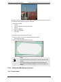
5.3.8.2 IP65/ IP66 Rated Detectors
For very harsh environmental conditions as they may appear at sites located off-shore or
even on-shore. Sometimes it is also necessary to have security devices cleaned on regular
bases, due to the end users operation (sandy or dusty environment). Then often high
pressure cleaning equipment is used.
Doc. 20780_03
15
Planning and Commissioning Manual
ADPRO Passive-Infrared (PIR) PRO Series by Xtralis
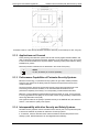
To avoid water ingress and condensation inside the housing a special membrane is
integrated into the housing. Condensation can happen e.g. when on a very hot sunny day
suddenly a severe weather with hail and rain cools down the air very quickly.
NOTE!
Special care has to be taken to the cable glands. To avoid water
ingress through the unused cable gland (the upper one in the image) it
shall be ensured that the sealing blinding is correctly inserted.
The following IP65-rated PIR detectors are available as part of the ADPRO PRO range:
PRO-18H/IP65
PRO-18WH/IP65
PRO-18WIS
PRO-45H/IP65
PRO-45DH/IP65
PRO-85H/IP65
PRO-100H-IP65
PRO-100HIS
The following IP66-rated PIR detectors are available as part of the ADPRO PRO range:
5.4
PRO-85H/IP66
PRO-100H-IP66
Detector Placement (Typical Design
Recommendation)
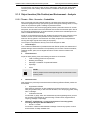
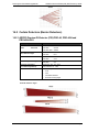
For Passive Infrared Perimeter Intrusion Detecion Systems (PIR-PIDS) it is recommended to
terminate the detection area with a fence or any artificial barrier so as to avoid receiving
readings caused by the detector’s nominal range and overlength.
The figure shows the detector’s over-length and how the detection area is terminated so as
not to detect unnecessary movement; thus, reduce the false alarm rate.
The distance at which to terminate the detection area depends on the detector’s model.
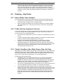
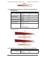
5.4.1 Simple Monitoring of an Enclosure with a Simple Boundary
5.4.1.1 Requirements
Monitoring of a higher fence surmounted by barbed wire.
The inner area remains unmonitored. Each alarm from a detector leads to an alarm or a
camera circuit.
16
Doc. 20780_03
ADPRO Passive-Infrared (PIR) PRO Series by Xtralis
Planning and Commissioning Manual
5.4.1.2 Planning
Because of these circumstances a curtain detector should be used; depending on the size of
the area the following detectors might be considered:
PRO-40
PRO-45, PRO-45H, PRO-45D, PRO-45DH
PRO-51
PRO-85, PRO-85H
PRO-100, PRO-100H
PRO-250H
In this case, a very narrow PRO-45 was chosen.
NOTE!
Creep zones are monitored by precedent detectors.
Over-length is avoided by using the existing fence.
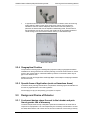
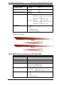
5.4.2 Monitoring of an enclosure with particularly careful
monitoring of the corners
5.4.2.1 Requirements
Monitoring of all four sides of a medium-high fence, with barbed wire around the top, on the
inside. Particular attention is paid to the corner areas, because the bases of the poles can be
easily mounted, and thus gives an incentive to climb over. The interior remains largely
unmonitored. Each alarm from a detector leads to an alarm or a camera circuit.
5.4.2.2 Planning
Doc. 20780_03
17
Planning and Commissioning Manual
ADPRO Passive-Infrared (PIR) PRO Series by Xtralis
Because of these circumstances a curtain detector should be used; depending on the size of
the area the following detectors might be considered.
For monitoring the sides:
PRO-40
PRO-45, PRO-45H, PRO-45D, PRO-45DH
PRO-51
PRO-85, PRO-85H
PRO-100, PRO-100H
PRO-250H
In this case a very narrow PRO-45 was chosen.
For extra coverage in the sides, the following detectors are offered:
PRO-18W, PRO-18WH
In this case a wide-angle PRO-18WH was chosen.
NOTE!
Creep zones are better monitored by the volumetric detectors in the
corners.
Over-length is avoided by using additional fixed IR-blocking foils.
These have to be maintained regularly so that loose swinging is not
possible.
5.4.3 Continuous Monitoring of an Area
5.4.3.1 Requirements
18
Doc. 20780_03
ADPRO Passive-Infrared (PIR) PRO Series by Xtralis
Planning and Commissioning Manual
The monitoring of the area needs not be complete, but should be as full as possible. This
corresponds to a continuous coverage strategy. A criminal must get to the middle of the
area, regardless of which side he uses for his attempt to enter.
5.4.3.2 Planning
Because of these circumstances, ideally only volumetric detectors should be used.
Depending on the size of the area the following detectors might be considered:
PRO-18, PRO-18H
PRO-30
PRO-40
PRO-51
PRO-85, PRO-85H
In this case a standard volumetric PRO-30 was chosen.
NOTE!
This is a very suitable arrangement for programming an A/B alarm or
cross zoning of two detectors. It may be possible to dispense with a
range termination, because an alarm will be triggered only, if the two
detectors within the perimeter boundary are activated.
5.4.4 Extensive Monitoring, or Monitoring of Borders, such as of a
Country
5.4.4.1 Requirements
An absolutely seamless and very secure monitoring of an elongated, large area, or of a
country’s borders, for the use of the security services.
The highest possible detection rate will be assumed. The false alarm rate should be in a
framework that can be mapped by an organisation (border monitoring: c. 10-12%).
5.4.4.2 Planning
Because of these circumstances, normally a curtain detector with a very large nominal range
should be used.
Depending on the application the following detectors might be considered:
PRO-45, PRO-45H, PRO-45D, PRO-45DH
PRO-100, PRO-100H
PRO-250H
Doc. 20780_03
19
Planning and Commissioning Manual
ADPRO Passive-Infrared (PIR) PRO Series by Xtralis
In this case a PRO-100H was chosen, on the one hand for a homogenous, seamless curtain,
and on the other, because the division into zones (near, middle, far) enables precise
detection of the location of a crime.
NOTE!
In regions with the climatic conditions of thick fog or snow is to be
expected, it is very important that the distance between the detectors is
at a maximum of 45-50 m.
If a video monitoring system with image analysis is used for verification
purposes, objective lenses with fixed focal lengths are usually required.
For a high quality of evaluation, it will be seen that this distance is also
desirable.
If an attempt at intrusion is only likely from one side, choosing a type of
detector with directional detection will lead to a reduction in false
alarms.
5.4.5 Monitoring of a Building with Dedicated Camera Surveillance
5.4.5.1 Requirements
An absolutely seamless and very secure monitoring of the exterior front of a building. The
highest possible detection rate will be assumed.
5.4.5.2 Planning
Because of the almost totally unfenced boundary of the property, only curtain detectors with
a narrow angle of aperture can be used. Depending on the length of the building the
following detectors are recommended:
PRO-45, PRO-45H
PRO-45D, PRO-45DH *
PRO-100, PRO-100H
PRO-250H
)
In this case a PRO-45DH was chosen.
20
Doc. 20780_03
ADPRO Passive-Infrared (PIR) PRO Series by Xtralis
Planning and Commissioning Manual
NOTE!
Because of the lack of range termination, it is important that a
management system includes a link between the detectors and the
right camera orientation mapping, so that the situation can be
assessed quickly and efficiently.
*) For certain applications, it may be a case of dealing not with
intruders, but with those who wish to break out from inside.
In this case detectors with directional detection (D-versions) can be
used to avoid false alarms. This applies, for instance, to prisons,
animal cages/ enclosures and parks.
5.5
False Alarms (according to DIN European Standard
0833-1)
False alarms can be classified as follows:
Technical alarm (Blind alarm):
The detector is defective, or has, for instance, been distorted by an electromagnetic
field.
Malicious alarm:
An alarm is triggered deliberately without actual need, for instance, false tripping of a
PIR detector by twisting.
False alarm:
A detector or alarm is ‘deceived’ by something that is similar to a real danger, such as
alarms caused by large animals, vehicle exhaust fumes or environmental factors.
Transmission errors:
It sometimes happens that transmission or communication errors cause false alarms
(a lack of competence with regard to the particular place, or false assumptions).
5.5.1 Causes of False Alarms
5.5.1.1 Insufficiently Stable Poles or Masts (Swinging)
When mounting ADPRO PRO detectors, always ensure that there is a solid surface, in the
form of a stable and vibration-free wall. If the mounting is on a mast, it must be secure so
that even in unfavourable weather (particularly wind), there is very little or no rocking at the
upper end of the mast.
Doc. 20780_03
21
Planning and Commissioning Manual
ADPRO Passive-Infrared (PIR) PRO Series by Xtralis
It is important to consider the wind load, especially if there are additional security features
such as CCTV cameras, LED lights etc., on the mast.
ADPRO PRO PIR detectors are light in weight and have a wind-resistant housing design,
and so offer little resistance to the wind.
5.5.1.2 Insufficiently Fixed Fences
In practice, one commonly occurring source of false alarms is barriers, that is, mechanical
fences themselves. These are often rarely serviced after a few years.
Due to weather, fences, in particular chain-link fences, become loose and start to sway in the
wind.
This generates noise signals, which are certainly compensated for by the ATD function, but
over time the performance capability of the system may lessen.
Therefore, make absolutely sure that any overhanging branches or foliage are removed.
Often plastic sheeting or bags are blown against the mesh, leading to noise signals.
5.5.1.3 Air Conditioners, Ventilation Shafts, Exhaust Pipes, Chimneys
As described in section 5.2.3, there is a range of environmental factors that can affect the
performance capability of the system. By appropriate placement most of these can be
avoided.
5.5.1.4 Walls and other Artificial Boundaries (Requirements)
Walls make ideal range boundaries. If there are no walls, stable, attached flagstones can be
useful.
The use of screens and tarpaulins is discouraged.
5.5.1.5 Logical Connection of Several Detectors
If physical separation is not possible, for aesthetic or financial reasons, this must be
considered in the planning and subsequent orientation of the detector.
First, attention must be paid to the areas where the monitored areas overlap considerably.
It can thus be sensible to connect to a burglar alarm system or safety management system.
It is simpler to use an appropriate detector.
See Section 14.1.2 IPT-Interactive Detectors.
5.5.2 No Alarm
In contrast to the false alarm, there can be no alarm, which impacts negatively on the quality
of a perimeter security system. Quite apart from the effects of the weather, as described in
section 5.2.3, errors in configuration and/or insufficient parameterisation can lead to a poor
detection rate.
5.5.2.1 Low Sensitivity
One reason for this can be that the detector sensitivity has been reduced too much, for fear
of too many false alarms, or because of the circumstances described in sections 5.2.1 and
5.2.2. In the event of, for instance, snow, rain or thick fog, even a perfectly calibrated system
might not be triggered if the signal strength is no longer sufficient or the alarm threshold is
too high. In this case the system must be adapted over time as a result of experience. One
possible measure is described in section 5.5.2.2.
5.5.2.2 A/B Alarm (double knock)
22
Doc. 20780_03
ADPRO Passive-Infrared (PIR) PRO Series by Xtralis
Planning and Commissioning Manual
One possible way to avoid false alarms is to use a so-called A/B alarm or ‘double knock’,
that is, two detectors connected.
Only when two detectors go into alarm is there a major alarm.
If this option is chosen, very precise analysis and planning is required.
Even this measure can lead to false alarms if not installed perfectly; when, for instance, there
is very thick fog between the two detectors.
Doc. 20780_03
23
Planning and Commissioning Manual
6
Installation
6.1
Detector Installation
ADPRO Passive-Infrared (PIR) PRO Series by Xtralis
6.1.1 Safety Instructions for Installation
Personnel
Work on the electrical system must only be performed by qualified electricians.
Improper Installation and Start-up
Warning!
Risk of injury through improper installation and start-up!
Improper installation and start-up can lead to serious personal injury or
property damage.
Therefore:
Be careful with open, sharp-edged components.
Before installation, ensure that the device has not been
damaged in transport.
Before installation, ensure that all transport packaging and/or
transport safety devices have been removed from the device.
Working from Height
DANGER!
Danger of falling down! There is acute danger, when working with
unsecured ladders. Unsecured ladders can slip and cause a fall
that can lead to serious injuries.
Therefore:
Before starting work, secure the ladder against slipping and
ensure at any time a save rest.
A secure access path to all man-carrying platforms and working
places must be ensured.
All places on which work is performed, as well as the access
paths to there, have to be illuminated in a sufficient way.
Additional information: refer to local “Safety at Work Act”.
6.1.2 Wiring
When preparing for wiring the detectors, it is critical to follow the local wiring regulations and
apply their standards for the spacing between the various existing cables. Having the
detectors wired close to high-voltage connections affects the signals and may lead to false
alarms, inaccurate readings, etc
6.1.3 Mounting
Preparation
The mounting surface must be stable to avoid false alarms from vibrations.
24
Doc. 20780_03
ADPRO Passive-Infrared (PIR) PRO Series by Xtralis
Planning and Commissioning Manual
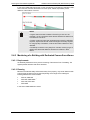
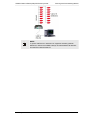
NOTE!
For further assistance, labels have been placed under the detector’s
housing cover. They explain the DIP switch settings and wiring labels.
They must be read before mounting the detector.
To mount the detector, follow these steps:
1.
Screw the bracket tightly to a wall or pole with at least two screws,
2.
For the model PRO-250H: Screw the detector to a pole with the provided pole bracket,
ZA P L1 (available as accessory for all other models, see chapter 12).
Mount the detector 2.5 m to 4 m (8 ft to 13 ft) above the ground,
3.
4.
5.
Open the cover by unscrewing the 2 cover screws,
Pass the cable through the cable gland into the detector’s housing,
Strip the cable and the wires,
6.
Connect the power supply according to the wiring plan on the sticker inside the cover
(see also the wiring plan in chapter 14),
Tighten the cable gland.
7.
Doc. 20780_03
25
Planning and Commissioning Manual
ADPRO Passive-Infrared (PIR) PRO Series by Xtralis
The detector is now ready for alignment.
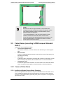
6.1.4 Alignment
The detection range of a PIR detector is not limited but a function of size, speed and
temperature contrast of a target against its background. The detector should be aligned so
that a natural or artificial background at the end of the range terminates the field of view.
Where the detection range has to be limited, a terminating screen can be used to avoid
detection of targets beyond the wanted range.
Vertical alignment is optimal when the upper edge of the field of view is at 1.5 to 2.5 m above
ground at the end of the required detection range provided that the field of view is properly
terminated. Coarse alignment can be done visually by looking along the grove on top of the
detector.
Accurate fine alignment is easily achieved with the help of the Alignment Telescope AD 851,
which can be placed on top of the detector for this purpose.
Preparation
NOTE!
For an optimal function of the detector:
Limit the detection range to a natural or artificial background
(e.g. a wall).
Do not align the detector to a mesh wire fence.
Ensure that no moving objects (e.g. branches, bushes, fences)
or body of water are within the detection zone.
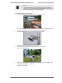
6.1.4.1 Coarse Alignment
To align the detector, follow these steps:
1.
Look along the groove on the detector’s cover,
2.
26
Locate a person or fixed-point at the nominal detection range and approximately 1.50
m (5 ft) height,
Doc. 20780_03
ADPRO Passive-Infrared (PIR) PRO Series by Xtralis
Planning and Commissioning Manual
NOTE!
The nominal detection range varies depending on the detector model.
For the nominal range of the detector models see technical data in
chapter 16.
3.
Retighten the screw.
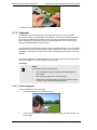
6.1.4.2 Accurate Fine Alignment
The AD 851 fits all detector models and should be used for fine alignment.
6.1.4.3 Finalization of Installation
Retighten the screw carefully.
NOTE!
Be careful that the position of the detector is not panned or tilt during
this process.
6.1.4.4 Ready for Walk Test
The detector is now ready for commissioning.This can be done either using the hardware
mode or software mode as it will be explained in the following sections.
Doc. 20780_03
27
Planning and Commissioning Manual
ADPRO Passive-Infrared (PIR) PRO Series by Xtralis
7
Operating Modes
7.1
Selectable Operating Modes
The detector can work in two operating modes:
Hardware mode
Software mode
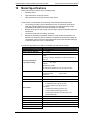
The devices of all models are provided with the following features.
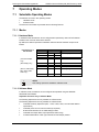
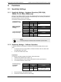
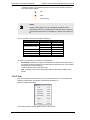
7.1.1 Modes
7.1.1.1 Hardware Mode
In hardware mode the detector can be configured and operated by means of DIP switches
located on the connector board of the detector.
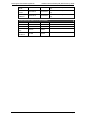
By default, the detector operates in hardware mode and the DIP switches are pre-set as
follows:
Default Settings of
DIP Switches
DIP Switch
1
2
3
4
(Volumetric Models
only)
(PRO-45D(H) only)
(PRO-51, PRO-85(H),
PRO-100(H), PRO250H only)
4
5
6
7
Status
ON
Function
Sensitivity adjustment
OFF
ON
ON
ATD
Pulse count
OFF
OFF
Directional detection
Test
Anti-tamper
Mounting height
OFF
No function
ON
ON
8
NOTE!
More setting options are available in software mode.
7.1.1.2 Software Mode
In software mode, the detector can be configured and operated using the ADPRO®
Windows® PRO software.
Adjustable Functions only in Software Mode
The following adjustments are only available in software mode:
The following adjustments are only available in software mode:
28
Individual sensitivity adjustment (20% - 140% or 50%-150%, see individual detector
specification)
Individual pulse count for volume models (0-10 pulses)
Bi-directional detection for the PRO-45D(H) models
Individual anti-tamper alarm output (transistor and/or relay)
Activation/deactivation of left/ right channels for PRO-45D(H) models
Doc. 20780_03
ADPRO Passive-Infrared (PIR) PRO Series by Xtralis
Planning and Commissioning Manual
Activation/deactivation of small/medium/large channels for long-range curtain models
PRO-100, PRO-100H and PRO-250H
Activation/deactivation of left/middle/right channels for multi-zone volumetric models
PRO-85 and PRO-85H.
Doc. 20780_03
29
Planning and Commissioning Manual
ADPRO Passive-Infrared (PIR) PRO Series by Xtralis
8
Commissioning
8.1
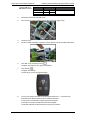
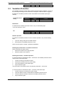
Walk Test
According to European Standard 50131-2-2, ‘Walk Test’ is defined as follows:
The walk test is an operating test in which the detector is stimulated by a standard walk test
object in a monitored area.
A standard walk test subject is a person of normal height and weight who is plausibly
dressed as an intruder.
This test is used to install a detector for normal operation, in the best way for the desired
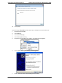
monitoring area, in order to achieve on the one hand the highest possible detection rate
(DR), and on the other the lowest possible false alarm rate (FAR).
The walk test can be performed when installing both hardware and software.
Using the alarm outputs, the test can be performed without auxiliary devices. For a more
accurate and reliable calibration, the use of an optional CT-PRO wireless walk tester, or
connection to a PC via the serial RS-485 interface, is recommended.
8.1.1 Walk Test – Hardware Mode
To perform the walk test in hardware mode, follow these steps:
1.
Keep the default settings of DIP switches 1 and 2,
2.
Set DIP switch 3 to “OFF” to deactivate the adaptive threshold discrimination (ATD)
function. See section 9.2 for further details,
3.
Close the cover,
DIP Switch Settings
for Adjustments
DIP Switch
1
2
3
4.
Status
ON
OFF
OFF
Function
100% sensitivity hardware
mode
ATD Function
Perform the walk test.
It is recommended that, initially, a preview with a detector pre-adjusted with a
telescopic sight is carried out, according to the corresponding area to be monitored
(see the overview of installed detectors in chapter 20).
Start with the maximum distance.
Proceed at a 90° angle to the longitudinal axis of the area to be monitored.
If there is no alarm in the area you are testing, re-adjust the angle of vision.
If the alarm trigger is correct, next check the lateral areas.
To avoid false alarms, make sure that there is no over-reaching.
Finally, cross the area several times at different distances and in different directions.
After the test
After the walk test, do the following:
1.
Set DIP switch 3 (ATD function) to “ON“,
2.
Fix the aligned detector horizontally with a nut underneath,
3.
Fix the aligned detector vertically with a nut on the right side.
Optimising Detection
30
Doc. 20780_03
ADPRO Passive-Infrared (PIR) PRO Series by Xtralis
Planning and Commissioning Manual
NOTE!
Repeat the walk test several times under various light intensities (e.g.
daylight, dawn) and weather conditions (e.g. wind, rain, snow, hail) to
optimise the detection on a basis of various data.
Furthermore, the performance of the detectors can be improved when
the subject, in addition to walking upright with his arms at his sides,
tries different postures, such as crawling on the floor on his hands and
knees.
8.1.2 Walk Test – Hardware Operation with CT-PRO Wireless Walk
Tester
The cordless walk tester, CT PRO 2, is an accessory for checking the detector alignment
remotely. During a walk test it indicates a detector alarm with a beeper and an LED. The
walk tester CT PRO 2 consists of a transmitter (CT PRO 2-T) and a receiver (CT PRO 2-R).
8.1.3 Receiver
LED Description
Power: LED indicates power is on and battery OK, dims when voltage is low.
Connectivity: LED indicates communication with transmitter is OK.
Signal: LED bar indicates the received signal strength of a test person during walktest
8.1.4 Transmitter
1.
Doc. 20780_03
Do not change the factory settings of DIP switches 1 and 2,
31
Planning and Commissioning Manual
Factory Settings of
DIP Switches 1 and 2
DIP-Switch
1
2
3
32
ADPRO Passive-Infrared (PIR) PRO Series by Xtralis
Status
ON
Function
100% sensitivity hardware
OFF
OFF
ATD-Function
2.
3.
Disconnect the RS-485 plug (left circle),
Connect the CT-PRO transmitter with the RJ12 connector (right circle),
4.
5.
Close the cover,
Fix the CT-PRO transmitter to the bottom of the detector with the provided cable strap,
6.
Click ‘ON’ on the CT-PRO receiver. (
),
The green LED lights up. The yellow LED flashes.
7.
Click ‘buzzer’. (
),
The green LED flashes.
The red LEDs (1) show the signal strength.
8.
You can now perform the walk test as described in section 8.1.1. Cross the area
several times at different distances and in different directions.
A high level on the LED bar indicates strong sensor signals.
A low level on the LED bar indicates weak sensor signals.
The buzzer indicates an alarm within the zone being monitored.
Doc. 20780_03
ADPRO Passive-Infrared (PIR) PRO Series by Xtralis
Planning and Commissioning Manual
If the desired detection range is not attained:
1.
Slightly realign the detector upwards,
2.
Repeat the walk test.
If the sensitivity is too high:
1.
Reduce the sensitivity to 75% (18,30,40,45 only) or the range (PRO-51, PRO-85,
PRO-100, PRO-150) by setting DIP switch 1 to “OFF” and DIP switch 2 to “ON”,
2.
Repeat the walk test.
If the sensitivity is still too high:
1.
Reduce the sensitivity to 40% (18,30,40,45 only) or the range even further (PRO-51,
PRO-85, PRO-100, PRO-150) by by setting DIP switch 2 to “OFF”,
2.
Repeat the walk test,
For the overall sensitivity settings of the detector set by DIP switches 1 and 2, see the
following table.
The following settings for detector sensitivity are possible with the use of DIP switches
1 and 2.
DIP-switch
ON
ON
1
2
ON
1
2
1
2
Doc. 20780_03
Status
1
2
OFF
OFF
ON
OFF
OFF
Function
Adjustable sensitivity available
only in software mode;
depending on detector model
100% HW sensitivity (PRO-18,
PRO-30, PRO-40, PRO-45)
Full HW range (PRO-51,
PRO-85, PRO-100, PRO-250)
75% HW sensitivity (PRO-18,
PRO-30, PRO-40, PRO-45)
Medium HW range (PRO-51,
PRO-85, PRO-100, PRO-250)
40% HW sensitivity
(18/30/40/45)
Low HW range
33
Planning and Commissioning Manual
ADPRO Passive-Infrared (PIR) PRO Series by Xtralis
(51/85/100/250)
Fixation
If the desired performance is reached:
1.
Fix the aligned detector horizontally with a nut underneath.
2.
Fix the aligned detector vertically with a nut on the right side.
NOTES!
Be careful NOT to change the aligned position of the detector.
After the test
1.
Remove the cable strap,
2.
Open the cover,
3.
Unplug the CT-PRO transmitter,
4.
Reconnect the RS-485 plug:
5.
Close the housing tightly with both screws.
The alignment is concluded.
8.1.5 Walk Test – Software Operation
Performing walk test using ADPRO Windows® software:
1.
Install the software (for installation instructions, see chapter 10),
2.
Open the cover of the detector,
3.
Connect the detector to a PC via an RS-485 connection, either through the RJ12 test
socket or the A/B lines (see diagram in chapter 13.2),
4.
Set DIP switch 1 and DIP switch 2 to “ON”:
34
Doc. 20780_03
ADPRO Passive-Infrared (PIR) PRO Series by Xtralis
DIP Switch Settings
for Software Mode
DIP-Switch
1
2
Planning and Commissioning Manual
Status
ON
ON
Function
Software mode
Display the Signal Strength
5.
With the PRO software (see chapter 10), you can change the settings (instead of
using DIP switches) and check the detector’s signal and alarm performance by doing
a walk test (instead using of the CT PRO).
Doc. 20780_03
35
Planning and Commissioning Manual
ADPRO Passive-Infrared (PIR) PRO Series by Xtralis
9
Functions
9.1
Sensitivity Settings
9.1.1 Sensitivity Settings – Hardware Operation (PRO-18(H),
18W(H), 30, 40, 45(H), 45D(H) only)
Detectors cover different detection ranges. The optimal sensitivity for the nominal range and
the width of the nominal range is preset to the default settings. The sensitivity is determined
by the DIP switches 1 and 2 on the board.
The following sensitivity settings are available:
Standard Setting of
DIP Switches 1 and 2
DIP-Switch
1
2
Medium Sensitivity/
Medium Range of
Coverage
Status
ON
OFF
DIP-Switch
1
2
Low Sensitivity/ Short
Range of Coverage
Status
OFF
ON
DIP-Switch
Status
1
2
OFF
OFF
Function
100% sensitivity at nominal
range
Function
75% sensitivity in hardware
mode
Function
40% sensitivity in hardware
mode
NOTE!
Sensitivity settings in hardware mode are limited to preset values.
9.1.2 Sensitivity Settings – Software Operation
In software operation the sensitivity of a detector can be set individually within a preset
range:
For detectors with long range (PRO-51, PRO-85, PRO-85H, PRO-100, PRO-100H
and PRO-250H): 50%-150%.
For all other models: 20%-140%.
Preparations
To change the sensitivity settings with software, follow these steps:
1.
Install the PRO software (see chapter 10),
2.
Connect the detector to a PC using the IFM-485-ST interface (see chapter 7),
3.
Turn the DIP switches 1 and 2 to “ON”.
DIP Switch Settings
for Hardware
Operation
DIP-Switch
1
2
4.
5.
36
Status
ON
ON
Function
Adjustable sensitivity available
only in software mode;
depending on detector model
Set the sensitivity in the software settings,
Disconnect the detector from the power supply.
Doc. 20780_03
ADPRO Passive-Infrared (PIR) PRO Series by Xtralis
Planning and Commissioning Manual
The individual sensitivity setting is saved.
NOTE!
Do NOT change the settings of DIP switches 1 and 2, because the
individual sensitivity settings are set by the hardware installation
override.
NOTE!
If the required detection range coincides with the denominator replaced
by the range, no adjustment of the detection distance is necessary.
If the required coverage area is smaller than the nominal range, there
may be frequent false alarms.
Nominal Ranges
Information on the nominal ranges of models of detectors are in the technical data in chapter
16.
9.2
Adaptive Threshold Discrimination (ATD)
Any thermal radiation will be converted by the pyro element into an electrical signal; as will
smaller signals, such as those produced by animals. These small signals are called ‘noise
signals’.
When the ATD function is left off, this leads after a certain time to a summation of the signals
and thus to a low signal-noise ratio. This can lead to false alarms. This system would be too
sensitive.
If the ATD function is on, these signals would be evaluated by complex algorithms, and the
Alarm Threshold Level would be automatically raised by an adequate amount. To make the
system not completely insensitive, this is only possible to a factory preset maximal value.
With this function false alarms can be avoided and an optimal detection rate achieved.
NOTE!
1.
To minimize the occurrence of alarms the ATD function should
always be activated in normal operation.
2.
As already described before, this function must be turned off
during the walk test, otherwise, because the test subject will
frequently set off the alarm, it will be raised from the start and
the system itself, set to the highest possible sensitivity settings,
will only be tripped wrongly.
3.
For the last walk test the ATD function must be turned on.
The ATD function is activated by default.
Standard DIP Switch
Settings
DIP-Switch
3
Status
ON
Function
ATD
Deactivation
Turn DIP switch 3 to “OFF”.
DIP Switch Setting
Doc. 20780_03
DIP-Switch
Status
Function
37
Planning and Commissioning Manual
ADPRO Passive-Infrared (PIR) PRO Series by Xtralis
3
9.3
OFF
ATD
Vandalism Protection
The vandalism protection function offers increased protection against vandalism. As soon as
the previously stored alignment of the detector is changed a continuous alarm is triggered.
By default, the vandalism protection function is activated on the transistor output (open
collector).
Standard DIP Switch
Setting
DIP-Switch
6
Status
ON
Function
Vandalism Protection
Deactivation
To deactivate the vandalism protection function, carry out the following step:
Turn DIP switch 6 to “OFF”.
DIP
DIP-Switch
6
Status
OFF
Function
Vandalism Protection
Software Operation
To activate the vandalism protection funcion in software operation, carry out the following
steps:
1.
Open the ‘Setting’ dialogue of the PRO software,
2.
Set the option for vandalism protection to “ON”.
There are more options in chapter 10 (Software Installation).
Resetting the position after an unauthorised intrusion
These are the ways to stop the alarm:
1.
Remount the detector in its original position.
2.
Reset the position of the detector.
Resetting the Position – Hardware Operation
To reset the position of the detector within c. 60 seconds -the vandalism protection sensor
remains active, follow these steps:
1.
Leave the housing of the detector closed,
2.
Disconnect the detector from the power supply,
3.
Connect the detector to the power supply,
4.
Align the detector again.
The new position of the detector will be automatically saved after c. 60 seconds.
To reset the position of the detector within c. 5 minutes, follow these steps:
1.
Leave the detector connected to the power supply,
2.
Open the detector housing to deactivate the vandalism protection sensor,
3.
Close the detector housing to activate the vandalism protection sensor,
4.
Align the detector again.
38
Doc. 20780_03
ADPRO Passive-Infrared (PIR) PRO Series by Xtralis
Planning and Commissioning Manual
The new position of the detector will be automatically saved after c. 5 minutes.
To reset the detector within 5 minutes, follow these steps:
1.
Disconnect the detector from the power supply,
2.
Connect the detector to the power supply again.
The new position of the detector will be saved immediately.
Resetting the Position - Software Operation
To reset the position of the detector in software operation, follow these steps:
1.
Open the ‘Setting’ dialogue in the PRO software,
2.
Set the option ‘Reset anti-tamper position’ to “ON”.
More details are given in chapter 7.
Resetting during Normal Operation
To reset the position of the detector during normal operation, follow these steps:
1.
Disconnect the detector from the power supply,
2.
Connect the detector to the power supply again.
The new position of the detector will be automatically saved after c. 60 seconds.
Resetting during Normal Operation in Software Operation
See chapter 7.
9.4
Intelligent Digital Signal Processing
The detector is automatically set with this function. Background noise and repeated
movements can be analyzed and balanced to minimize false alarms.
The threshold level is exceeded when background noises or repetitive movements increase
within c. 1-2 minutes of the end of the event.
Several preset parameters are analyzed. When there is a signal corresponding to one of the
preset parameters an alarm is triggered.
9.5
Internal Temperature Compensation
The detector is automatically set with this function. This compensates a variation in signal
strength due to different light levels and weather conditions.
9.6
Pulse Count
(Volumetric Models Only)
To reduce the false alarm rate, the pulse counter delays the activation of the alarm for a
preset number of pulses after the alarm criteria have been reached.
By default, three pulses are added to the first start pulse.
The alarm will be activated after 4 pulses.
Standard DIP Switch
Settings
DIP-Switch
4
Doc. 20780_03
Status
ON
Function
Pulse Counter
39
Planning and Commissioning Manual
ADPRO Passive-Infrared (PIR) PRO Series by Xtralis
Deactivation
To deactivate the pulse counter function, follow this step:
Turn DIP switch 4 to “OFF“.
An alarm is activated after one pulse count.
DIP Switch Setting
DIP-Switch
Status
OFF
4
9.7
Function
Pulse counter
Directional Detection
(Models PRO-45D, PRO-45DH only)
This function enables monitoring of a detection area in particular directions to reduce false
alarms and improve the performance of the detector. Movement from left to right and right to
left can be recognized. Moreover, in software operation bi-directional detection can be set.
NOTE!
DIP switch 4 is only used in models (PRO-45D and PRO-45DH) for
directional detection.
For volume models (PRO-18, PRO-18H, PRO-30, PRO-40, PRO-51,
PRO-85, PRO-85H) DIP switch 4 is used for the impulse counter.
On other models DIP switch 4 has no function.
DIP Switch settings
DIP-Switch
4
4
Status
OFF
ON
Function
from left to right
from right to left
To change directional detection:
Set DIP switch 4 to “ON“.
Bi-Directional Detection
To activate the bi-directional detection, follow these steps:
1.
Set DIP switches 1 and 2 to “ON” to change to software mode,
2.
Open the “Setting” menu,
3.
Choose “Bi-directional” from the drop-down menu “SW Directional detection”.
9.8
Mounting Height Adjustment
PRO-51, PRO-85, PRO-85H, PRO-100, PRO-100H, PRO-250H only
The mounting height feature allows the adjustment of the detector´s sensitivity in relation to
the mounting height. This feature is available for long-range detectors only.
DIP Switch Position
DIP Switch
7
7
40
Status
ON
OFF
Function
Higher > 3 m (10 ft.)
Lower < 3 m (10 ft.)
Doc. 20780_03
ADPRO Passive-Infrared (PIR) PRO Series by Xtralis
Planning and Commissioning Manual
If the detector is mounted lower than 3 m (10 ft.):
Set DIP switch 7 to “OFF“.
9.9
Internal Heating Device
High Performance Detectors (H-models) only
A controlled heating device, connected to the electronic board and powered by the power
supply of the detector, prevents condensation forming on the optical surfaces and ensures
optimal internal temperature.
Doc. 20780_03
41
Planning and Commissioning Manual
10
ADPRO Passive-Infrared (PIR) PRO Series by Xtralis
Software Installation
The ADPRO PRO Windows® Software is available as an accessory to the interface module
“IFM-485-ST (formerly IF-485B)”. It is used for commissioning of challenging installations,
optimizing the settings and monitoring the detector/s in use. It can be used for all types of
detectors.
The Software shows all current operation parameters and analog signals of each detector in
real time. This is useful in various situations, such as realignment of the detector, adapting
certain parameters or blanking out objects in the detection area causing unwanted alarms.
NOTE!
The software’s name has been changed from “IF-485B” to “IFM-485ST”; it has the same functionality, but with the following enhancements:
Destruction of the unit due to over-voltage is avoidable.
Accidental reverse of polarity will not cause damage to the unit.
10.1 System Requirements
Before installing the ADPRO PRO Windows® Software, make sure that the following
requirements are available in the computer:
Microsoft® Windows® PC
Communication Ports: USB or RS232
10.2 Install Software
The ADPRO PRO Windows® Software installation wizard allows you to easily install the
Software by providing you with direct and easy-to-follow steps whether installation is made
on an XP or Windows 7 platform.
This section discusses how to install the Software on Windows 7 and XP platforms, in
addition to configuring the communication port.
10.2.1 Install on Windows 7 Platform
To install the Software on a Windows 7 platform, do the following:
42
1.
Unzip the file “Setup_PROXX.zip”,
2.
Rename the file “Setup_PROXX.txt” to “Setup PROXX.exe”,
3.
Double click the file “Setup PROXX.exe”, a Security Warning window appears,
4.
Click (Run), a User Account Control window appears,
5.
Click (Yes), the ADPRO Setup Wizard installation wizard starts and the following
window appears:
Doc. 20780_03
ADPRO Passive-Infrared (PIR) PRO Series by Xtralis
Planning and Commissioning Manual
If you want to cancel the installation process, click (Cancel), the following message
appears:
Click (Yes) to cancel the installation process, or (No) to resume it. You can reinstall
the Software later.
6.
Click (Next), the following window appears:
You can save the ADPRO PRO Windows® Software in the selected folder or specify
another one by clicking (Browse) then selecting it.
7.
Doc. 20780_03
Click (Next), the following window appears:
43
Planning and Commissioning Manual
ADPRO Passive-Infrared (PIR) PRO Series by Xtralis
The window shows where the Software’s shortcuts will be created, if you want to
specify another folder, click (Browse) and select it.
You can return to the previous window to make the changes you want by clicking
(Back). This button is available in all windows.
8.
Click (Next), the following window appears:
The window shows the destination location and start menu folder you specified.
9.
44
Click (Install), the following window appears:
Doc. 20780_03
ADPRO Passive-Infrared (PIR) PRO Series by Xtralis
Planning and Commissioning Manual
10.
Wait till the installation is complete, the following window appears:
11.
Click (Finish).
10.2.2 Install on XP Platform
To install the Software on an XP platform, follow these steps:
1.
Unzip the file “Setup_PROXX.zip”,
2.
Rename the file “Setup_PROXX.txt” to “Setup PROXX.exe”,
3.
Double click the file “Setup PROXX.exe”, the ADPRO Setup Wizard starts and the
following window appears:
Doc. 20780_03
45
Planning and Commissioning Manual
4.
ADPRO Passive-Infrared (PIR) PRO Series by Xtralis
Click (Next), the following window appears:
You can save the ADPRO PRO Windows® Software in the selected folder or specify
another one by clicking (Browse) then selecting it.
5.
46
Click (Next), the following window appears:
Doc. 20780_03
ADPRO Passive-Infrared (PIR) PRO Series by Xtralis
Planning and Commissioning Manual
The window shows where the Software’s shortcuts will be created, if you want to
specify another folder, click (Browse) and select it.
6.
Click (Next), the following window appears:
The window shows the destination location and start menu folder you specified.
7.
Click (Install), the following window appears:
8.
Wait till the installation is complete, the following window appears:
Doc. 20780_03
47
Planning and Commissioning Manual
9.
ADPRO Passive-Infrared (PIR) PRO Series by Xtralis
Click (Finish).
The ADPRO PRO Windows® Software is now installed in your computer in the specified
directory and the following structure is created:
Each sub-folder is responsible for a specification action as follows:
:
Contains all images taken using the Software.
:
Contains all detector configuration files.
:
Contains all statistics and debugger files.
:
Contains all detectors definition files. Each detector model
requires its specific INI file.
:
Contains specific data relevant to the display structure such as
logo on images, etc. This file must not be deleted.
:
Installation program for setup and signal display.
10.2.3 Configure Communication Port
It is important to configure the communication port that will be dedicated to the Software
before you start using it.
48
Doc. 20780_03
ADPRO Passive-Infrared (PIR) PRO Series by Xtralis
Planning and Commissioning Manual
If you are using a Windows 7 platform, follow these steps to configure the port:
1.
Connect the “IFM-485-ST” to the available port,
2.
Right click “My Computer”,
3.
Click “Manage”,
4.
Click “Device Manager”,
5.
Click “Ports (COM and LPT)”, a list of available ports appears as shown next:
6.
Right click “USB Serial Port (COM3)” to update its driver software,
7.
Click (Update Driver Software…), the following window appears:
8.
Select “Search automatically for updated driver software”, the following window
appears:
9.
Wait for the search to complete, the following window appears:
Doc. 20780_03
49
Planning and Commissioning Manual
10.
ADPRO Passive-Infrared (PIR) PRO Series by Xtralis
Click (Close).
If you are using an XP platform, follow these steps to configure the communication port:
50
1.
Right click “My Computer”,
2.
Click “Manage”,
3.
Click “Device Manager”,
4.
Click “Ports (COM and LPT)”,
5.
Right click “Communications Port (COM1)”, the following menu appears:
6.
Click (Update Driver…), the following window apppears:
7.
Select “Install the software automatically (Recommended)”,
Doc. 20780_03
ADPRO Passive-Infrared (PIR) PRO Series by Xtralis
Planning and Commissioning Manual
8.
Click (Next), the following window appears:
9.
Wait while the wizard searches for the update, the following window appears:
10.
Click (Finish).
NOTE!
You can directly connect to the IFM-485-ST via the RS232 com.
Every time you change the communication port you are using,
you need to reconfigure its driver software.
Port number varies depending on the system you are using.
For more information on how to associate the communication port with the Software, refer to
section (10.3.2 Select Communication Port).
10.3 Use Software
As mentioned earlier, the Software helps you to optimize the settings and monitor the
detector(s) in use. After you have successfully mounted the detector and configured the
settings you need, you can start using the Software.
Doc. 20780_03
51
Planning and Commissioning Manual
ADPRO Passive-Infrared (PIR) PRO Series by Xtralis
Once installed, a shortcut is created for the ADPRO PRO Windows® Software and can be
accessed through the applications menu, it appears as follows:
Activate the Software, the following window appears:
The ADPRO PRO Windows® Software provides various tools and features that allow you to
control and monitor the detectors and maximize their benefit. They are categorized into
menus for easier access.
In addition, you can access any tool or feature through the buttons that appear in the toolbar
as follows:
Image
Action
Open Detector INI
Search Detector
Up/download settings
Debugger
Statistics
Scope
View picture
Run
Stop
Take picture
Moreover, the Software provides shortcuts through the keyboard for faster access to the
required tool, as follows.
Shortcut
<F1>
<F2>
<F3>
<F4>
<Ctrl> + B
52
Action
About the Software
Open detector definition file window.
Search for a detector.
Up/Download
Beep
Doc. 20780_03
ADPRO Passive-Infrared (PIR) PRO Series by Xtralis
<F5>
<Ctrl> + <F5>
<F6>
<F7>
<F8>
<Ctrl> + <F8>
<F9>
<F10>
<Ctrl> + <K>
<Ctrl> + <P>
<Ctrl> + <V>
<Ctrl> + <A>
<Ctrl> + <O>
<Ctrl> + <M>
<Ctrl> + <T>
<Ctrl> + <D>
Planning and Commissioning Manual
Run scope
Stop scope
Change scroll direction, “right to left” or “left to right”
Hide/ show grid
Increase signal speed
Decrease signal speed
Clear scope
Delete all triggers
Open scope window
Take picture
View picture
Picture auto
Picture memo
Open statistics window
Test
Open debugger window
The following sections discuss all the actions you can perform, the available tools and how to
use them.
10.3.1 Select Detector
Before you start using the ADPRO PRO Windows® Software, you need to select the
detector to be used. The Software normally finds the detector’s definition file automatically;
however, this step is performed only if there is no automatic loading.
There are two methods for selecting the detector in use in order to load its definition file and
connect it to the “IFM-485-ST” data bus.
First method:
1.
Click “File”,
2.
Click (Open Detector INI),the following appears:
3.
Select the detector,
4.
Click (Open).
Second method:
1.
Click “Option”,
2.
Click (Search Detector),the following window appears:
Doc. 20780_03
53
Planning and Commissioning Manual
ADPRO Passive-Infrared (PIR) PRO Series by Xtralis
NOTE!
Detectors are given IDs (addresses) in the range of 1 to 254. Factoryset addresses are in the 1 to 10 range. It is recommended to narrow
down the range when searching for a detector so as not to take time
and retrieve the connected detectors more quickly.
Each detector must have a unique address, if more than one detector
is given the same address and connected to the same bus, none of
them will appear on the Software. To resolve this problem, disconnect
all detectors and configure each one separately. This will ensure that
no detector uses the same ID of another one.
3.
Click (Start), or press keys <ALT> + <S>, a list of found detectors appears as shown
below:
The number on the left of the “>” sign is the detector’s ID. The type of the detector and
the firmware version number are on the right of the “>” sign.
You can stop the search process by pressing <ALT> + <S> or clicking (Stop).
To close the search window, click (ESC).
If no detectors are found, the following message appears:
54
Doc. 20780_03
ADPRO Passive-Infrared (PIR) PRO Series by Xtralis
Planning and Commissioning Manual
The message shows the possible reasons for not retrieving any detector. Click (OK),
check the error, and repeat the search.
4.
Select the detector you want, or enter its identification number in “Choice” field,
5.
Click (OK).
If you select the wrong detector, the following message appears:
Click (OK) then select the correct detector.
10.3.2 Select Communication Port
To select the communication port to which the “IFM-485-ST” data bus will be connected,
follow these steps:
1.
Click “Option”,
2.
Click “Com Port”, a menu listing the available ports appears,
3.
Select the port you want; it will be marked with a (
) sign.
NOTE!
Communication ports’ numbers vary according to the system you are
using and available ports.
10.3.3 File
This option enables you to select the detector in use in order to load its definition file and
connect it to the “IFM-485-ST” data bus.
For more information, refer to section (10.3.1 Select Detector).
10.3.4 Option
Through this menu you can search for a certain detector, upload/ download detector
settings, select port, etc.
Option appears as shown next:
Doc. 20780_03
55
Planning and Commissioning Manual
ADPRO Passive-Infrared (PIR) PRO Series by Xtralis
The following sections discuss, in detail, the actions you can perform.
10.3.4.1
Search Detector
To search for a detector, refer to section (10.3.1 Select Detector).
10.3.4.2
Up/Download
The Software simplifies the process of detectors configuration and allows you to save time
spent in setting other detectors values. You can configure a detector and use the same
settings for other detectors of the same type connected to the Software.
You can manage setting options, upload a detector’s settings, download them from a
definition file, and save them to a new definition file, etc.
The Up/Download window appears as follows:
Settings window is detector-model-dependent and is primarily designed to review and
change detector’s parameters. These include the overall sensitivity, mounting height, etc.
The window shows the detailed setting options of the selected detector. It also shows the
actions you can perform where each one is represented with a certain button as follows:
Image
Action
Upload settings to detector
Download detector’s settings
Copy
Insert
Save to configuration file
Load from configuration file
56
Doc. 20780_03
ADPRO Passive-Infrared (PIR) PRO Series by Xtralis
Planning and Commissioning Manual
Also, the above actions can be accessed by clicking “Setting”, the following menu appears:
The following sections discuss all the actions you can perform, the available tools and how to
use them.
NOTE!
Setting options depend on detector model.
Displayed positions and displayed terms of option may vary depending
on detector model.
To select a detector to load its settings, you can:
Select the detector from the drop-down menu then click (
Press <F3> and search for it by following the same steps mentioned in section (10.3.1
Select Detector), then click (
10.3.4.2.1
).
).
Setting Options
The Setting window displays the setting options for the selected detector where each field
represents a certain value as follows:
Choice
Lists all detectors of the same model.
Address
Displays selected detector’s identification number.
Configuration
Displays current operation mode: Hardware or Software.
NOTE!
Operation modes can only set by DIPswitches 1 and 2 on connector board of
detector.
SW range
Detection range can be individually set in seven steps. Preset values vary depending on model.
Reduction of nominal range affects only coverage of longrange channel (applies to long-range models only).
SW sensibility/
SW sensitivity
[%]
Modifies the overall sensitivity within a bandwidth 50% 150%.
Reduction of overall sensitivity changes alarm threshold but
leaves coverage of long-range channel unchanged.
1
Channel L/M/S
Channel
2
right/left
Doc. 20780_03
ON
Long, medium and short range channels may be enabled
individually by selecting “ON” from drop-down menu.
OFF
Long, medium and short range channels may be disabled
individually by selecting “OFF” from drop-down menu.
ON/
OFF
Enables/ Disables right/ left channel.
57
Planning and Commissioning Manual
ADPRO Passive-Infrared (PIR) PRO Series by Xtralis
Modifies sensitivity of right/left channel within bandwidth 20
% - 139.39 %.
Reduction of overall sensitivity changes alarm threshold but
leaves coverage of right/left channel unchanged.
SW sensitivity
1
right/left [%]
SW ATD
ON
Enables “Adaptive Threshold Discrimination”.
OFF
Disables “Adaptive Threshold Discrimination”.
NOTE!
Disable ATD function prior to walking test
to optimize performance of detector.
When putting “SW Test” to “ON”, ATD
function is disabled automatically in
Software mode.
SW Test
ON
Enabled to perform walking test with Wireless walking tester
CT-PRO.
OFF
Disabled for normal operation.
SW Vandalism
protection/SW
vandal function
ON/
OFF
Enables/ Disables “Anti-Tamper Protection”.
Reset vandal
position
ON
Writes new alignment position into non-volatile RAM as
baseline for anti-tamper protection in case of misalignments.
OFF
Upload of settings to control device happens always
automatically in “OFF”.
-
Not selected.
OFF
Disables output function of relay.
ON
Enables output function of relay.
Relay function
If relay function is set to “ON”, the following two options are
available in the drop-down menu:
1. “IR + VAN | IR + VAN”: Using relay and transistor open
collector to signal intrusion alarms and tamper alarms.
2. “IR + VAN”: Using only relay to signal intrusion alarms
and using only transistor open collector to signal tamper
alarms. This allows identifying alarms.
Output function
[Relay |
Transistor]
Reset alarm
counter
Relay output
logic
SW pulse count
2
ON
Resets alarm counter to “zero” at next download of settings
to detector.
OFF
No resetting of alarm counter to “zero” at next download of
settings to detector.
Upload of settings to control device happens automatically
in “OFF”.
-
Not selected.
Normal
Relay opens when in alarm.
Inverted
Relay closes when in alarm.
0 - 10
Number of additional pulses (0 – 10) before an alarm is
generated.
OFF
Disables “Adaptive Threshold Discrimination”.
NOTE!
Disable ATD function prior to walking test
to optimize performance of detector.
3
SW Mounting
58
HIGH
Mounting height above than 3 m (10 ft).
LOW
Mounting height less than 3 m (10 ft).
1
Applies only to long-range detector models
2
Applies only to directional detector models
3
Applies only to volume detector models
Doc. 20780_03
ADPRO Passive-Infrared (PIR) PRO Series by Xtralis
Planning and Commissioning Manual
Also, the Setting window provides you with additional information regarding the setting
options, as shown in the following figure:
The above example shows help information regarding the detector’s address.
To view the help information of any other field, simply place the cursor in the required field
and the information appears in the upper box.
To close the Setting window, click (
).
NOTE!
If you attempt to close the Settings window before saving the changes
you make, the following message appears:
If you are sure you want to exit the window without saving, click (Yes);
otherwise, click (No) then save the changes you made.
10.3.4.2.2
Upload Settings
To upload settings to detector, follow these steps:
1.
Make the changes you want to the fields you can change,
2.
Click (
). Successful upload is represented with (
).
NOTE!
Make sure to click (
they are lost.
10.3.4.2.3
) to save the changes you made; otherwise,
Factory Settings
You can reinstate the factory default configuration to the detector instead of the changes you
made in the following cases:
Doc. 20780_03
59
Planning and Commissioning Manual
ADPRO Passive-Infrared (PIR) PRO Series by Xtralis
The detector does not seem to work properly.
A previous version of the ADPRO PRO Windows® Software was used on the same
detector.
To display and use the factory default settings, follow these steps:
1.
Click (Factory), the following message appears:
2.
Click (Yes) to replace the values with the factory ones,
3.
Click (
10.3.4.2.4
) to save them in the detector’s configuration file.
Download Settings
To download the detector’s settings, follow these steps:
1.
Make the changes you want,
2.
Select the detector,
3.
Click (
).
The configuration status is represented with the following symbols:
10.3.4.2.5
:
Uploading configuration
:
Changed configuration
:
Communication problem
:
Downloading configuration
Copy Settings
To copy the settings of a detector and use them in another one, follow these steps:
1.
Select the detector which settings you want to copy,
2.
Click (
3.
Select the detector to which you want to apply the copied settings,
4.
Click (
10.3.4.2.6
),
).
Save Settings to CFG File
To save the configuration in the “CFG” sub-folder accessed through the ADPRO PRO
Windows® Software folder saved in the computer, follow these steps:
1.
60
Make the changes you want,
Doc. 20780_03
ADPRO Passive-Infrared (PIR) PRO Series by Xtralis
Planning and Commissioning Manual
2.
Click (
3.
Enter file name,
4.
Click (OK) to save, or (Abort) to cancel the action.
10.3.4.2.7
), the following field appears:
Load Settings from CFG File
To load the configuration saved in a CFG file, follow these steps:
1.
Click (
2.
Select the file,
3.
Click (Open), the configuration appears in the Settings window so you can make sure
you are using the desired configuration.
4.
Click (
10.3.4.3
), the following window appears:
) to upload settings to detector.
Com Port
For more information on how to select the port you want to use, refer to section (10.3.2
Select Communication Port).
10.3.4.4
Language
The Software provides the settings and parameters in various languages displayed in this
menu.
To switch between the available languages, follow these steps:
1.
Click “Language”,
2.
Select the language you want.
Parameters and settings are now displayed in the selected language, but as for the interface
language itself it is only available in English.
10.3.4.5
Doc. 20780_03
Beep
61
Planning and Commissioning Manual
ADPRO Passive-Infrared (PIR) PRO Series by Xtralis
If this option is checked, whenever the detector detects something, you’ll hear a beep.
10.3.5 Scope
The Scope view is the most powerful feature of the software. It shows in real-time the signal
strength of each zone, if the monitored detector features multiple detection zones.
Simultaneously, it shows the actual alarm threshold, the general alarm status, and various
parameters such as total alarm count, strongest signal level received, and current settings of
the DIP switches in the detector, etc.
Through this menu you can manage the Scope view by stopping or running it, selecting the
view mode, increase or decrease signal speed, etc.
Scope menu appears as shown below:
Scope view appears as follows:
The Scope view illustrates the cause/response relationship between inputs and output. The
view shows all signals and their levels on a time axis ; it allows for a detailed analysis of the
detector’s operation.
The Scope view appears automatically after a detector has been selected from the search
list. The signals on the screen represent the current readings of the detector and are helpful
for resolving problems as well as managing certain installation features.
The Scope window is divided into the following three parts:
Scope view (1): Scope view is used to for signal monitoring; it shows IR amplitude,
alarm-threshold and other vital parameters in real-time. In addition, it shows a varying
amount of lines as follows:
62
Green (Sensor Signal): shows the signal levels of the PIR sensor.
Doc. 20780_03
ADPRO Passive-Infrared (PIR) PRO Series by Xtralis
Planning and Commissioning Manual
Red (IR Alarm): shows the IR event caused by the sensor signal.
Purple (Master Alarm): shows the actual output signal at relay.
Blue (Alarm threshold).
Yellow (Actual status).
NOTE!
Alarms appear on Scope view only if the alarm generating detector is
selected.
Table of Settings (2): This table shows the current settings of the selected detector; it
consists of the detector’s parameters such as sensitivity, desired detection range, their
values and unit.
To view the values of a certain parameter, click it, its values appear as shown below:
The selected parameter’s values appear in view-mode only. Any changes made to the
settings are directly reflected on this table and the threshold.
NOTE!
Information displayed in table may vary depending on detector model.
Settings of DIP-switches, port and address information (3): You can view the status
of the DIP-switches that were set upon configuring the detector, and other information as
shown in the following figure:
1. Status of current DIP-switches.
2. Used port.
3. Detector´s identification number.
Doc. 20780_03
63
Planning and Commissioning Manual
ADPRO Passive-Infrared (PIR) PRO Series by Xtralis
4. Detector’s status, it is represented with an arrow which color changes according to
the current status as follows:
:
OK
:
Fault
:
Synchronizing
NOTE!
Display of DIP-switches may vary depending on detector model.
DIP-switches values are controlled from the detector itself. A table that
shows the switches functions is available on a sticker on the detector’s
lid.
You can control the Scope view through the following:
Action
Run the Scope
Stop the Scope
Select Scope view mode
Increase signal speed
Decrease signal speed
Clear Scope view
Delete all triggers
Button
Run
Stop
Scroll Mode
Grid
Step up++
Step down- Clear
Trigger Delete ALL
Shortcut
<F5>
<Ctrl> + <F5>
<F6>
<F7>
<F8>
<Ctrl> + <F8>
<F9>
<F10>
As shown in the table above, there are two scope modes:
Scroll Mode: If checked, the signal is continuous and its direction is from right to left. If
unchecked, the signal’s direction is from left to right and each time <F6> key is pressed
the signal starts from the beginning.
To switch between Scroll modes press <F6>.
Grid: If selected, horizontal and vertical lines appear on the Scope in addition to the
signals.
10.3.6 Tool
This menu enables you to take pictures of the scope and save them in the computer, view
statistics of alarm states, and identify communication problems, etc.
Tool menu appears as follows:
The following sections discuss all the actions you can perform.
64
Doc. 20780_03
ADPRO Passive-Infrared (PIR) PRO Series by Xtralis
10.3.6.1
Planning and Commissioning Manual
Scope
To open the Scope view, click (Scope) or press <Ctrl> + <K>.
For more information on actions you can perform in Scope view, refer to section (10.3.5
Scope).
10.3.6.2
Picture Take
This tool enables you to take pictures of the Scope view and save them in the “BMP” subfolder accessed through the ADPRO PRO Windows® Software folder. You can use them to
compare readings, monitor readings on certain times, etc.
To take a picture and save it, follow these steps:
1.
Click (Picture take), the following field appears:
2.
Enter your comment,
3.
Click (OK).
The picture is saved in the BMP and given a name according to the following naming
convention:
“PRO-Model No-yymmdd_nnn.txt” where: yy=year, mm=month, dd= day, nnn=sequential
number (1 - 999).
To view a picture, open it from the computer, it appears as follows:
Doc. 20780_03
65
Planning and Commissioning Manual
ADPRO Passive-Infrared (PIR) PRO Series by Xtralis
The image shows the Scope, comment, and settings at the time that picture was saved.
However, pictures can be viewed from the Software itself as explained in the next section.
10.3.6.3
Picture View
You can view the pictures directly from the Software for easier access by clicking (Picture
view). The following window appears:
66
Doc. 20780_03
ADPRO Passive-Infrared (PIR) PRO Series by Xtralis
Planning and Commissioning Manual
The window is divided into two parts: the left one lists all the pictures and the right a preview
of the selected picture.
To delete a picture, follow these steps:
1.
Select the picture, its name is displayed in the field,
2.
Click (Delete). It is immediately deleted from this window and from the “BMP” folder as
well.
To close the window, click (
10.3.6.4
).
Picture Auto
If this feature is checked, each time the detector reads a signal or detects a movement, a
picture is automatically taken and saved in the “BMP” folder.
10.3.6.5
Picture Memo
If this feature is checked, the “Picture take” tool is activated and you can take pictures of the
Scope.
10.3.6.6
Statistics
Through this feature you can view data the detector transmits to the controller. The Statistics
view logs the actual alarm status of all detectors that have been discovered during the initial
“Search for Detectors” process. In addition to general alarm information, the view details the
zone that issued the alarm. It also shows warnings and detector‘s status under the system
column. Every status change from every detector adds a line in this log view.
This information is stored in text files on a daily basis, one file per detector. Files are saved
in the “DAT” sub-folder accessed through the ADPRO PRO Windows® Software folder.
Click (Statistics), the following window appears:
Doc. 20780_03
67
Planning and Commissioning Manual
ADPRO Passive-Infrared (PIR) PRO Series by Xtralis
The window is divided into the following sections:
Connected Detectors (1): displays all connected detectors with information about
identification number, firmware version number and alarm counters.
Type (2): Each symbol indicates a status as follows:
(
): connected.
(
): not connected.
Log (3): Displays the actual log.
To generate a statistics file and save it, follow these steps:
1.
Enter file name,
2.
Click (
below:
) to start the viewing the transmitted data, it appears as in the example
Note that a line is created for each detected event, along with the date and event
description.
68
Doc. 20780_03
ADPRO Passive-Infrared (PIR) PRO Series by Xtralis
3.
Click (
Planning and Commissioning Manual
) to stop the process and save the file.
The file is saved in the “DAT” folder and named according to the following naming
convention:
“STAz-yymmdd_nnn.xxx” where: z=number of statistics file, yy=year, mm=month, dd= day,
nnn=sequential number (1 - 999), xxx=address number.
10.3.6.7
Debugger
This tool helps record all communication made between the detector and computer and save
this information in files stored in the computer. These files are saved in the “DAT” sub-folder
accessed through the ADPRO PRO Windows® Software folder.
Click (Debugger) to open the Debugger window, it appears as follows:
To start recording of data traffic and save this information in the computer, follow these
steps:
1.
Click the checkbox next to “Communication”, the window appears as follows:
2.
Click (New File).
Data is saved in the file; you can create another file by clicking (NewFile).
To stop recording of data, click (Clear).
Files are named according to the following naming convention:
Doc. 20780_03
69
Planning and Commissioning Manual
ADPRO Passive-Infrared (PIR) PRO Series by Xtralis
“DBG-yymmdd_nnn.txt” where: yy=year, mm=month, dd= day, nnn=sequential number (1 999).
The following abbreviations are used in data recording:
Abbreviation
ErrA
ErrK
ErrW
ErrP
ChkSum
Tmo
Buf
Error
Error counter
Error counter configuration
Error counter working
Error counter synchronisation
Error counter check sum
Error counter timeout
Error counter buffer
10.4 Uninstall Software
You might need to uninstall the ADPRO PRO Windows® Software for any reason; the
Software enables you to do so by providing you with a user-friendly wizard.
To uninstall the Software, follow these steps:
70
1.
Open the folder in which you have installed the Software,
2.
Double click on “unist000.exe”, the following message appears:
3.
Click (Yes), the following window appears:
4.
Wait till the uninstallation process is complete, the following message appears:
5.
Click (OK).
Doc. 20780_03
ADPRO Passive-Infrared (PIR) PRO Series by Xtralis
11
Planning and Commissioning Manual
Normal Operation
11.1 Connection Options
11.1.1 Contacts
All detectors can be connected with potential-free contacts or open collector outputs to other
systems such as:
CCTV monitoring
A burglar alarm system or
A management system
For the purposes of alarm transmission. This universal use is also guaranteed for proprietary
systems. The detectors also provide enough space for the installation of bus connection
modules of the respective systems
11.1.2 Permanent Links
If, however, detectors are continuously connected to a control centre, connection to a PC via
interface module IFM-485-ST is required. The detector must be in software operating mode.
Advantages
A continuous operation of the detector gives the following advantages:
Remote access setting (no work on a ladder, no accidental misadjustment)
Signal monitoring/ verification
Management of up to 16 detectors with a maximum bus length of 1000 m
Doc. 20780_03
71
Planning and Commissioning Manual
12
ADPRO Passive-Infrared (PIR) PRO Series by Xtralis
Accessories
12.1 IFM-485-ST - Interface Module RS-485
The IFM-485-ST is an interface module which allows you to convieniently connect the RS485 bus of the detector to the USB or RS-232 bus of your computer or control panel.
Advantages
This product gives the following advantages:
Alarm management/ monitoring signal
Remote access to detector
Connection of up to 16 detectors to a data bus (maximum bus length including
‘stitches’: 1000 m)
For use together with security and traffic detectors from Xtralis
Requirement
PRO software (see chapter 14).
12.2 AD 851 - Alignment Telescope
This scope enables precise adjustment of the detector over denominated detection ranges of
up to 150 m.
12.3 CT PRO2 - Wireless Walk Tester
The wireless walk tester CT PRO2 enables precise adjustments of the detector over the
nominal detection range. Optical, as well as acoustic indications, plus a LED bar showing the
signal strength makes this product a ‘must have’ tool.
72
Doc. 20780_03
ADPRO Passive-Infrared (PIR) PRO Series by Xtralis
Planning and Commissioning Manual
The CT PRO2 consists of a transmitter connected to the RS-485 test socket in the detector
and a battery-operated receiver.
12.4 ZA P-L1 – Pole-mount Attachment
Suitable for all models. This allows the detector to be mounted on a pole.
The attachment is suitable for masts with diameter of 40-160 mm.
12.5 AD653 - Pole-Mount for PRO-250H
Especially for PRO-250H. The detector can be mounted on a mast with this special holder.
The attachment is suitable for masts with diameter of 40-160 mm.
12.6 PRO-CMB-W - Cable Managed Bracket
This robust and durable cable managed bracket can be used for all detectors (not PRO250H). This optional accessory offers an easy and quick solution for an efficient installation.
Hidden cabling discouraging cable vandalism
Standard compliance
Tamper protection and detection (including sealable locking screw)
Tamper switch for detection of removal from mounting surface and opening the base
junction box
Automatic tamper alarm of the detector when housing is opened or tilt (vandalism
alarm)
Field of view respectively range, sensitivity and area adaptable
Doc. 20780_03
73
Planning and Commissioning Manual
ADPRO Passive-Infrared (PIR) PRO Series by Xtralis
Pre-wired for easy and fast installation
Off-site assembly preparation (address, parameter pre-setting etc.) to keep expensive
parts in a safe environment until they were needed)
Plug & Play final installation
An integrated 14-pin terminal in the base plate allows seperate wiring and detector
installation for an efficient work.
The bracket is retractable and can be opened at any time for maintenance or service
reasons. For your safety and convenience (hands-free) the bracket is kept in a retaining
fixture.
An additional pole mount accessory is also available as an option for hidden cabling on poles
to protect against vandalism.
12.6.1 PRO-CMB-S — Tamper-Switch (PRO-CMB-S)
In some applications or in some standards a removal from mounting surface is required. As
these requirements may not be covered by the “Tilt Alarm” an additional tamper-switch can
be built-in into the cable managed bracket. This tamper-switch is optional available as a
retro-fit kit.
The design and position of this tamper-switch is done in that way, that the removal from the
mounting surface, as well as the opening of the base-plate with the cable terminal inside, is
detected. This switch can be used as a separate zone or can be connected to the tamperswitch/tilt alarm of the detector housing. Refer to quick setup guide, provided with the
product shipment of PRO-CMB-W.
74
Doc. 20780_03
ADPRO Passive-Infrared (PIR) PRO Series by Xtralis
Planning and Commissioning Manual
May be the mounting surface is not always plane and smooth. This can be adjusted by the
screw (not included in the kit). It is recommended to have a distance of 6 mm between screw
head (upper edge) and the bottom surface of the cable managed bracket. Take care that the
connection cable is not trapped and can move easily to ensure both detections (remove and
opening).
NOTE!
For proper operation a final test is recommend as mandatory.
Doc. 20780_03
75
Planning and Commissioning Manual
13
ADPRO Passive-Infrared (PIR) PRO Series by Xtralis
Diagram
13.1 Terminal – Top view (all models except PRO-250H)
13.2 Terminal – Side view (all models except PRO-250H)
76
Doc. 20780_03
ADPRO Passive-Infrared (PIR) PRO Series by Xtralis
14
Planning and Commissioning Manual
Electrical Connections
14.1 Electrical Pin Assignment for Detectors
14.1.1 All Models (except PRO-250H)
14.1.2 PRO-250H
14.2 Connection of the interface module IFM-485-ST
14.2.1 A single detector to the interface module IFM-485-ST
1.
2.
Doc. 20780_03
Connect the RS-485-Bus of the detector via the RJ12 test jack or A / B cables to the
interface module IFM-485-ST.
Then connect the interface module to a PC on which you have previously installed
PRO software via a USB or RS-232 cable.
77
Planning and Commissioning Manual
ADPRO Passive-Infrared (PIR) PRO Series by Xtralis
14.2.2 Several detectors to the interface module IFM-485-ST
To connect more than one detector to a PC via the RS-485 data bus, follow these steps:
1.
Connect every detector to a computer on which the PRO software is running, and
allocate an individual address (1-254) to the software settings (see chapter 10.1.4).
Each address can be used only once.
2.
Connect detectors using parallel or star cabling.
3.
Install a terminating resistor of 120 Ω between terminals 485-A and 485-B on the
board of the last detector on the bus. In the interface module IFM-485-ST switchable
resistance is already installed. Thus the data connection is properly terminated at both
ends of the bus.
It is important to note that the total cable length including ‘stitches’ does not exceed 1000 m.
NOTE!
If more than one detector is connected to the interface module IFM-485-ST
each detector must have a unique address.
78
Doc. 20780_03
ADPRO Passive-Infrared (PIR) PRO Series by Xtralis
Planning and Commissioning Manual
NOTE!
To prevent malfunction or destruction of equipment caused by potential
differences, make sure that GND is always connected between all detectors
and interface module IFM-485-ST.
Doc. 20780_03
79
Planning and Commissioning Manual
15
ADPRO Passive-Infrared (PIR) PRO Series by Xtralis
Dimensions
All models (except PRO-250H) with metal bracket
All dimensions are in (mms).
PRO-250H
AD 653 Pole Mount for PRO-250H (optional)
80
Doc. 20780_03
ADPRO Passive-Infrared (PIR) PRO Series by Xtralis
16
Planning and Commissioning Manual
Model Specifications
Please note that three versions are to be distinguished:
Standard version
High Performance version (H-version)
High Performance version (H-version) in IP65 version
The H-version is characterized by the following enhanced features amongst others:
The housing face plate is not IR transparent film, but a mechanical, robust silicon
wafer disc specially developed for this application, and characterized by its high
permeability to IR radiation, as well as its resistance to sabotage.
Because of this precise optic greater nominal range compared to standard types can
be achieved.
H versions include a built-in heating mechanism.
Because of this heating, applicability extends to harsh climatic environments. The
detectors can be used in spite of variations in temperature, because the resulting air
condensation, which could cause signal attenuation due to water droplets building up
on the face plate or the mirror, is counteracted.
The following specifiations are valid for all ADPRO PRO-PIR detector models:
SPECIFICATIONS
All ADPRO PRO-PIR Detectors
Spectral response
8-14μm, double filter
Speed ranges for detection
0,2 – 5,0 m/s
DIPswitch
Sensitivity adjustments
(% per default setting)
: 40%, 75% 100%
Sensitivity or Range, depending on model, see section 16.1
and 16.2.
PRO
: 20 - 140%
software
depending on models:
all single-sensor detectors (18, 30, 40, 45): 20-140%
all multi-sensor detectors (51, 85, 100, 250): 50-150%
Window
Standard version
:
PE-Filter, IR transmissive
High-Performance
H-versions
:
Silicon wafer
Vandalism detection of housing
Tilt and housing opening detection (NC contact 30V/100 mA)
Alarm indication
Internal LED
PRO-xxx
Alarm outputs
1x relais SPST 30VDC @ 100 mA max.
1x open collector 30VDC @ 50 mA max.
PRO-250H
1x relais SPST 30VDC @ 100 mA max.
1x open-collektor 30VDC @ 50 mA max.
3x optocoupler outputs for one each alarm zone
(short/medium/long)
Communication
RS-485, 9,6kBit/s
Temperature compensation
Full compensation over the whole operating temperat. range
Supply voltage
10,5 - 30VDC, 24VAC ±15% (w/o heater)
Current consumption
18 mA @ 12VDC, 14 mA @ 24VDC
Power consumption of heater
2W / 176 mA @ 12 VDC and -40°C (H-versions only)
Operating temperature
Standard versions
Doc. 20780_03
: -20º up to +60°C
81
Planning and Commissioning Manual
ADPRO Passive-Infrared (PIR) PRO Series by Xtralis
SPECIFICATIONS
All ADPRO PRO-PIR Detectors
High-Performance H-versions
: -40° up to +60°C
Cable connection
(removable screw terminals)
PRO-xxx
PRO-250H
2 x 4-7 mm (0.16” - 0.27”)
2 x 6 – 9 mm (P11, 0,24” - 0,35”)
Cable glands
PRO-xx
Outside cable diameter: Ø 9 – 14 mm
PRO-250H
Outside cable diameter: Ø 4 – 10 mm
(M16)
IEC 60423:2007(DIN EN 60423) – cable glands
Weight
Dimensions (L x B x H) in mm
Mounting
(PG11)
All PRO-xxx
(except PRO-250H)
:
approx. 900 g,
w/ metal bracket
PRO-250H
:
approx. 1,5 kg, w/o bracket
All PRO-xxx
(except PRO-250H)
:
247 x 100 x 104
PRO-250H
:
272 x 100 x 104
All PRO-xxx (except PRO-250H):
Metal bracket (included in delivery)
Pole mount ZA P-L1 (optional)
Cable managed bracket PRO-CMB-W (optional)
PRO-250H:
Metal-Pole-/Wall-Mount AD 653 (optional)
IP rating
PRO-xxx:
IP54
The following models have been tested by TEA AG,
Schweizerischer Prüfstellendienst (Akkreditierungs-Nr. STS
506) to be compliant with the protection rating IP65:
PRO-18H-IP65
PRO-18WH-IP65
PRO-45H-IP65
PRO-45DH-IP65
PRO-85H-IP65
PRO-100H-IP65
The following models are compliant to IP66 rating:
PRO-85H-IP66
PRO-100H-IP66
Compliance
All ADPRO PRO-PIR detctors are designed to fulfill the
following guidelines:
UK: BS8418_Form 172 Basic Guide for Installers (CCTV with
PIR trigger)
(provided that all detectors are RS-485 cabled and in a permanent
online operation mode monitored by an alarm receiving, which
requires an interconnection to an intrusion, access control or CCTV
security system or an alarm management station)
All ADPRO PRO-PIR detectors have been tested and are
certified by the accredited test house HTZ in Zürich (notified
body number D.E.07.36/37_2), Switzerland and comply fully
to the following standards:
82
2004/108/EG
Directive of the European
Parliament relating to
electromagnetic compatibility
EN 61000–6–3:2007
Electromagn. Compat. – EMC
EN 50130–4
+A1+A2:2003 –
Electromagn. Compat. – Immunity
Doc. 20780_03
ADPRO Passive-Infrared (PIR) PRO Series by Xtralis
Environmental directives
Planning and Commissioning Manual
All ADPRO PRO PIR detectors meet the following EU
directives:
Directive 2002/95/EC
RoHS
Directive on the restriction of the use of certain
hazardous substances in electrical and
electronic equipment
Country of Origin
REACH
Regulation (EC) No 1907/2006
Registration, Evaluation, Authorisation and
Restriction of Chemicals (REACH) is a
European Union Regulation
WEEE
European Community directive 2002/96/EC
The Waste Electrical and Electronic
Equipment Directive (WEEE Directive)
“Swiss Premium Quality“ - Made in Switzerland
16.1 Volumetric Detectors
16.1.1 ADPRO Passive-IR-Detector PRO-18 and PRO-18H
Specifications
Model
Item code
Max. nominal Length
Nominal Width
ADPRO PRO-18 and PRO-18H
PRO-18:
PRO-18H:
PRO-18H/ IP65
201885
201886
202488
PRO-18:
PRO-18H:
24 m
30 m
PRO-18:
PRO-18H:
21 m
27 m
50°
Nominal Aperture angle (AA)
Sensitivity adjustment
(% of default adjustment)
Internal Switches
DIP-Switch:
PRO-Software:
40%, 75% 100%
20 - 140%
Sensitivity
ATD
Pulse Counter
Test
Vandalism Detection
Nominal mounting height
Nominal detection ranges
Doc. 20780_03
83
Planning and Commissioning Manual
ADPRO Passive-Infrared (PIR) PRO Series by Xtralis
16.1.2 ADPRO Passive-IR-Detector (PIR) PRO-18W and PRO-18WH
Specifications
Model
Item code
Max. nominal Length
Nominal Width
ADPRO PRO-18W/ PRO-18WH
PRO-18W:
201313
PRO-18WH:
201727
PRO-18WH/IP65 202489
PRO-18W:
PRO-18WH:
21 m
27 m
PRO-18W:
PRO-18WH:
24 m
30 m
DIP-Switch:
PRO-Software:
40%, 75% 100%
20 - 140%
90°
Nominal Aperture angle (AA)
Sensitivity adjustment
(% of default adjustment)
Internal Switches
Sensitivity
ATD
Pulse Counter
Test
Vandalism Detection
Nominal mounting height
Nominal detection ranges
84
Doc. 20780_03
ADPRO Passive-Infrared (PIR) PRO Series by Xtralis
Planning and Commissioning Manual
16.1.3 ADPRO Passive-IR-Detector (PIR) PRO-30
Specifications
Model
Item code
ADPRO PRO-30
PRO-30:
202383
Max. Nominal Length
30 m
Nominal Width
20 m
Nominal Aperture angle (AA)
50°
Sensitivity adjustment
(% of default adjustment)
DIP-Switch:
PRO Software:
40%, 75% 100%
20 - 140%
Internal Switches
Sensitivity
ATD
Pulse Counter
Test
Vandalism Detection
Nominal mounting height
Nominal detection ranges
16.1.4 ADPRO Passive-IR-Detector (PIR) PRO-40
Specifications
Model
Item code
ADPRO PRO-40
PRO-40:
202384
Max. Nominale Length
40 m
Nominal Width
10 m
Doc. 20780_03
85
Planning and Commissioning Manual
ADPRO Passive-Infrared (PIR) PRO Series by Xtralis
Specifications
ADPRO PRO-40
15°
Nominal Aperture angle (AA)
Sensitivity adjustment
(% of default adjustment)
DIP-Switch:
PRO Software:
40%, 75% 100%
20 - 140%
Internal Switches
Sensitivity
ATD
Pulse Counter
Test
Vandalism Detection
Nominal mounting height
Nominal detection ranges
16.1.5 ADPRO Passive-IR-Detector (PIR) PRO-51
Specifications
Model
Item code
ADPRO PRO-51
PRO-51:
202385
Max. Nominal Length
50 m
Nominal Width
23 m
Nominaler Aperture angle (AA)
26°
Sensitivity and range adjustment DIP-Switch:
PRO Software:
Length: 30, 40, 50 m
Length: 30, 40, 50 m
Sensitivity: 50 – 150%
Internal Switches
Range (length)
ATD
Pulse Counter
Test
Vandalism Detection
Nominal mounting height
Nominal detection ranges
86
Doc. 20780_03
ADPRO Passive-Infrared (PIR) PRO Series by Xtralis
Planning and Commissioning Manual
16.1.6 ADPRO Passive-IR-Detector (PIR) PRO-85 and PRO-85H
Specifications
Model
Item code
Max. Nominal Length
Nominal Width
ADPRO PRO- 85/PRO-85H
PRO-85:
PRO-85H:
PRO-85H/ IP65
201779
201780
202494
PRO-85:
PRO-85H:
60 m
75 m
PRO-85:
PRO-85H:
18 m
23 m
Nominaler Aperture angle (AA)
17°
Sensitivity and range adjustment PRO-85:
DIP-Switch:
PRO Software:
PRO Software:
DIP-Switch:
PRO Software:
PRO Software:
PRO-85H:
Internal Switches
Range (length)
ATD
Pulse Counter
Test
Vandalism Detection
Nominal mounting height
Length: 30, 45, 60 m
Length: 30, 45, 60 m
Sensitivity: 50- 150%
Length: 40, 60, 75 m
Length: 40, 60, 75 m
Sensitivity: 50- 150%
Nominal detection ranges
Doc. 20780_03
87
Planning and Commissioning Manual
ADPRO Passive-Infrared (PIR) PRO Series by Xtralis
16.2 Curtain Detectors (Barrier Detectors)
16.2.1 ADPRO Passive-IR-Detector (PIR) PRO-45, PRO-45H and
PRO-45H-IP65
Specifications
ADPRO PRO-45/PRO-45H
PRO-45:
PRO-45H:
PRO-45H/ IP65
201312
201736
202485
PRO-45:
PRO-45H:
50 m
60 m
Nominal Width
PRO-45:
PRO-45H:
3.3 m
3.9 m
Nominaler Aperture angle (AA)
PRO-45:
PRO-45H:
3.4°
3.8°
Sensitivity adjustment
(% of default adjustment)
DIP-Switch: 40%, 75% 100%
PRO Software: 20 - 140%
Internal Switch
Sensitivity
ATD
Test
Vandalism Detection
Nominal mounting height
Model
Item code
Max. Nominal Length
Nominal detection ranges
88
Doc. 20780_03
ADPRO Passive-Infrared (PIR) PRO Series by Xtralis
Planning and Commissioning Manual
16.2.2 ADPRO Passive-IR-Detector (PIR) PRO-45D, PRO-45DH and
PRO-45DH-IP65
Specifications
ADPRO PRO-45D/PRO-45DH
PRO-45D:
PRO-45DH:
PRO-45DH/ IP65:
201735
201737
202486
PRO-45D:
PRO-45DH:
50 m
60 m
Nominal Width
PRO-45D:
PRO-45DH:
3.6 m
4.2 m
Nominaler Aperture angle (AA)
PRO-45D:
PRO-45DH:
4°
4°
Sensitivity adjustment
(% of default adjustment)
DIP-Switch:
PRO Software:
Internal Switch
Sensitivity
ATD
Test
Vandalism Detection
Nominal mounting height
Model
Item code
Max. Nominal Length
40%, 75% 100%
20 - 140%
Nominal detection ranges
16.2.3 ADPRO Passive-IR-Detector (PIR) PRO-100 and PRO-100H
Specifications
Model
Doc. 20780_03
Item code
ADPRO PRO-100/PRO-100H
PRO-100:
PRO-100H:
PRO-100H/ IP65
225100
201738
202492
89
Planning and Commissioning Manual
ADPRO Passive-Infrared (PIR) PRO Series by Xtralis
Specifications
ADPRO PRO-100/PRO-100H
PRO-100:
PRO-100H:
120 m
150 m
Nominal Width
PRO-100:
PRO-100H:
2.9 m
3.3 m
Nominal Aperture angle (AA)
PRO-100:
PRO-100H:
1.3°
1.4°
Max. Nominal Length
Sensitivity and range adjustment PRO-100:
Length: 60, 80, 120 m
DIP-Switch:
PRO Software: Length: 60, 72, 84, 84, 96, 108,
120 m
PRO Software: Sensitivity: 50 - 150%
PRO-100H: DIP-Switch:
Length: 75, 105, 150m
PRO Software: Length: 75, 90, 105, 120, 135,
150 m
PRO Software: Sensitivity: 50 - 150%
Internal Switch
Range (length)
ATD
Test
Vandalism Detection
Nominal mounting height
Nominal detection ranges
16.2.4 ADPRO Passive-IR-Detector (PIR) PRO-250H
Specifications
Model
Item code
ADPRO PRO-250H
PRO-250H
150 m
Nominal Width
3.3 m
1.3°
Nominal Aperture angle (AA)
Alarm Output
1Relay SPST 30 VDC@100 mA max.
Open collector 30 VDC@50 mA max.
Alarm zone via 3opto-coupler outputs
Sensitivity and range adjustment DIP-Switch:
PRO Software:
Internal Switch
90
202405
Max. Nominale Length
Length: 75, 105, 150 m
Length: 75, 90, 105, 120, 135, 150 m
Sensitivity: 50 – 150%
Range (length)
ATD
Test
Vandalism Detection
Doc. 20780_03
ADPRO Passive-Infrared (PIR) PRO Series by Xtralis
Specifications
Planning and Commissioning Manual
ADPRO PRO-250H
Nominal mounting height
Nominal detection ranges
Doc. 20780_03
91
Planning and Commissioning Manual
17
ADPRO Passive-Infrared (PIR) PRO Series by Xtralis
Maintenance and Service
17.1 Safety
Personnel
Work on the electrical system must only be carried out by qualified electricians.
17.2 Environmental Protection
Environmental Damage
CAUTION!
Environmental threat due to incorrect handling!
Incorrect handling of environmentally hazardous substances, especially in
the event of improper disposal, can cause considerable damage to the
environment. Therefore:
Always take into account the information provided in the following.
If environmentally hazardous substances are accidentally released into
the environment, take immediate and appropriate measures. If in doubt,
inform the competent local authority about the damage.
17.3 Recommendations
The ADPRO® Passive Infrared Detector (PIR) PRO series is maintenance free.
Inspections
The following inspections are recommended:
Visual inspection of the outside:
1.
Check the front window for dirt and clean the surface with a damp cloth at least once
every 6 months.
Note!
Avoid rubbing dirt into the surface.
Take the same precautions for camera lenses.
2.
Check housing for damage at least once every 6 months.
Note!
Check that the sealing gasket is in the right place before closing cover tightly.
Inspections after extreme weather (e.g. snow storm, sand storm, hail):
1.
Check the detector for damage.
2.
Remove snow, sand or dirt from the front window.
3.
Check the detector for reduced sensitivity caused by accumulated snow, sand or dirt
on the front window.
92
Doc. 20780_03
ADPRO Passive-Infrared (PIR) PRO Series by Xtralis
18
Planning and Commissioning Manual
Troubleshooting
In the event of malfunctions, contact the manufacturer. For contact information see page 2 of
this manual.
18.1 False Alarms
Possible Cause
ATD (adaptive threshold
discrimination) is off.
Animals in the detection area.
Moving vegetation caused by
wind or moving animals.
Sensitivity of the device is too
high.
Thermal sources.
Doc. 20780_03
Possible Solution
Activate ATD (through DIP switch 3 "on" or PRO
software settings).
Check for animals. If necessary, fence the detection
area.
Check for moving vegetation (e.g. branches or leaves).
If necessary, remove or prune the disturbing vegetation.
If necessary, reduce the sensitivity. (DIP switch 1&2 or
PRO software settings).
Check for thermal sources within the range of the
device (e.g. kitchen exhaust or exhaust from an air
conditioning system). If necessary, adjust the direction
of the device or screen away from the thermal sources.
93
Planning and Commissioning Manual
19
ADPRO Passive-Infrared (PIR) PRO Series by Xtralis
Disassembly and Disposal
Once its service life has expired, the device must be disassembled and disposed of using an
environmentally safe procedure.
19.1 Safety
Personnel
Work on the electrical system must only be carried out by qualified electricians.
19.2 Environmental Protection
Environmental Damage
ACHTUNG!
Environmental threat due to incorrect handling!
Incorrect handling of environmentally hazardous substances, especially in the
event of improper disposal can cause considerable damage to the
environment. Therefore:
Always take into account the information provided in the following.
If environmentally hazardous substances are accidentally released into
the environment, take immediate and appropriate measures. If in doubt,
inform the competent local authority about the damage.
If there is no return or disposal agreement, disassembled components should be recycled
as:
Scrap metals
Plastic items for recycling
Other components sorted by material properties
The local authority or a waste disposal specialist will provide information on envinronmentally
compatible disposal.
19.3 Measures before Disassembly
Before starting disassembly:
1.
Turn off the power.
2.
Secure the main switch with a padlock against switching on again.
94
Doc. 20780_03
ADPRO Passive-Infrared (PIR) PRO Series by Xtralis
20
Planning and Commissioning Manual
Product Overview
Detection
Principle
Volumetric,
medium-range
Model
Code
PRO-18
201885
PRO-18H
201886
PRO-18H/ IP 65
202488
PRO-18W
Volumetric, widePRO-18WH
range
PRO-18WH/ IP 65
Nominal Range
Length
Width
24 m (80 ft)
21 m (70 ft)
30 m (100 ft)
27 m (90 ft)
201313
21 m (70 ft)
24 m (80 ft)
201727
27 m (90 ft)
30 m (100 ft)
202489
27 m (90 ft)
30 m (100 ft)
Angle
50°
90°
Volumetric,
medium-range
PRO-30
202383
30 m (100 ft)
20 m (65 ft)
50°
Volumetric,
medium-range
PRO-40
202384
40 m (130 ft)
10 m (33 ft)
15°
201312
50 m (165 ft)
3.3 m (11 ft)
3.8°
60 m (200 ft)
3.9 m (13 ft)
3.4°
50 m (165 ft)
3.6 m (12 ft)
60 m (200 ft)
4.2 m (14 ft)
202484
50 m (165 ft)
3.3 m (11 ft)
3.3°
CH10080101
50 m (165 ft)
23 m (75 ft)
34°
PRO-85
201779
60 m (200 ft)
18 m (60 ft)
PRO-85H
201780
PRO-85H/ IP 65
202494
75 m (250 ft)
23 m (75 ft)
PRO-85H/ IP 66
202495
120 m (400 ft)
2.9 m (9 ft)
1.3°
150 m (500 ft)
3.3 m (11 ft)
1.4°
202405
150 m (500 ft)
3.3 m (11 ft)
1.3°
PRO-45
Curtain, mediumPRO-45H
range
PRO-45H/ IP 65
Curtain,
directional,
medium-range
201735
PRO-45DH
201737
PRO-45DH/ IP65
202486
PRO-51
Curtain, longrange
202485
PRO-45D
Curtain, mediumPRO-45Z
range
Volumetric, longrange
201736
PRO-100
225100
PRO-100H
201738
PRO-100H/ IP 65
202492
PRO-100H/ IP 66
202493
Curtain, longrange, step-down PRO-250H
look
4°
17°
Accessoiries
AD 653,
pole-mount for
PRO-250H
ZA P 100-U1
220103
Standard pole-mount with stainless steel
clamps
pole-mount for
PRO-250H
ZA P 100-M1
on request
Special pole-mount for heavy duty
applications
Pole-mount for
all detectors
ZA P-L1
201753
Do not use for ADPRO PRO-250H
Cable Managed
Bracket
PRO-CMB-W
CH18310001
Tamper Switch
PRO-CMB-S
(retro-fit) for CMB
CH18320001
Interface Module,
IFM-485-ST
RS-485 Bus
CH19000301
PRO-Telescope
ZA P 03
242600
Walk Tester,
wirelss
CT PRO 2
202483
Doc. 20780_03
Alignment Telescope
95
Planning and Commissioning Manual
ADPRO Passive-Infrared (PIR) PRO Series by Xtralis
Ex-Barrier,
RS-485
PRO-SBB IS
CH19200001
For use with Intrinsically Safe detectors
only
Ex-Barrier,
contacts
PRO-SBC IS
CH19200101
For use with Intrinsically Safe detectors
only
Power Supply for
PRO-PS2 IS
Ex-Barriers
CH19210001
For use with Intrinsically Safe detectors
only
Obsolete (these item codes are no more available)
CT 44
96
Walk Tester
CT 45
201909
Walk Tester
CT PRO
202465
Volumetric, longrange
PRO-50
202385
Interface Module,
IF 485B
RS-485 Bus
201908
Doc. 20780_03
ADPRO Passive-Infrared (PIR) PRO Series by Xtralis
Planning and Commissioning Manual
www.xtralis.com
The Americas +1 781 740 2223 Asia +852 2916 8876 Australia and New Zealand +61 3 9936 7000
UK and Europe +44 1442 242 330 Middle East +962 6 588 5622
The contents of this document are provided on an “as is” basis. No representation or warranty (either express or implied) is
made as to the completeness, accuracy or reliability of the contents of this document. The manufacturer reserves the right to
change designs or specifications without obligation and without further notice. Except as otherwise provided, all warranties,
express or implied, including without limitation any implied warranties of merchantability and fitness for a particular purpose are
expressly excluded.
This document includes registered and unregistered trademarks. All trademarks displayed are the trademarks of their
respective owners. Your use of this document does not constitute or create a licence or any other right to use the name and/or
trademark and/or label.
This document is subject to copyright owned by Xtralis AG (“Xtralis”). You agree not to copy, communicate to the public, adapt,
distribute transfer sell modify or publish any contents of this document without the express prior written consent of Xtralis
Doc. 20780_03
P/N 201699.01