1
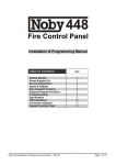
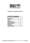
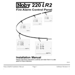
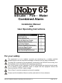
65
Intruder - Fire - Water
Combined Alarm
Installation Manual
and
User Operating Instructions
TABLE OF CONTENTS
First Power-Up
Power Supply Unit
Input & Detection Circuits
Output & Alarm Circuits
Keyswitch Options
Remote Signalling Equipment
Technical Specification
Connection Diagrams
User Operating Instructions
Page
2
3
3
5
6
6
7
8 -10
11 -12
For your safety:
This equipment is to be installed, serviced and maintained by a suitably qualified
technical person with the requisite knowledge of electrical and fire safety installations.
The Noby-65 is intended to be permanently connected to the 230VAC house wiring via a
2A fused spur and in accordance with local wiring regulations.
Part of the internal circuitry operates at 230VAC and presents an electrical shock hazard.
Do not attempt to open, dismantle, repair or tamper with this equipment without first
disconnecting the 230VAC supply voltage.
This is Class-1 electrical equipment and must be earthed.
Please read this Installation Manual carefully and retain for future reference.
Noby-65 Installation Manual & Operating Instructions (Rev.1)
Page 1 of 12
FIRST POWER-UP
We strongly recommend that the Noby-65 is first powered up with all 10K End Of Line resistors fitted at the panel,
as supplied by the factory. In this way you can gain confidence that the panel is operating correctly before
introducing detector and sounder circuits.
Power-Up With Battery
• Turn the Keyswitch to the OFF position.
• Connect the black battery lead to the battery –‘ve terminal.
• Connect the red battery lead to the battery +’ve terminal. It is normal to see a small spark.
• 60s Start-up Period: i) All LEDs flash for 60s *.
ii) The Buzzer output will make a pulsing sound (if connected).
After Start-up:
i) The green Power LED flashes.
ii) The yellow Fault/Alarm LED is lit.
iii) The red Sabotage LED is lit (because Noby-65 lid is removed).
* The 60s Start-up Period can be prematurely terminated by turning the Keyswitch to FULL for 4s,
and then back to OFF.
• Perform a System Reset: Momentarily turn the Keyswitch to FULL and then to OFF within 2s.
Observe a 2s LED test.
• After System Reset: i) The green Power LED is off (because the 230VAC is absent).
ii) The yellow Fault/Alarm LED is lit.
iii) The red Sabotage LED is lit (because Noby-65 lid is removed).
• Connect 230VAC supply to the 230v/50Hz AC screw terminal block.
• Replace the Noby-65 panel lid: observe the yellow Fault/Alarm LED turn off.
• Switch on the 230VAC power and observe the green Power LED flash (indicating 230VAC restored).
• Perform a System Reset: momentarily turn the Keyswitch to FULL and then to OFF within 2s.
Observe a 2s LED test.
• The panel should now be in a quiescent standby state with only the green Power LED lit.
Power-Up With 230VAC
• Turn the Keyswitch to the OFF position.
• Connect a 230VAC power supply to the 230v/50Hz AC screw terminal block, and switch on.
• 60s Start-up Period: i) All LEDs flash for 60s *.
ii) The Buzzer output will make a pulsing sound (if connected).
After Start-up:
i) The green Power LED will flash.
ii) The yellow Fault/Alarm LED will be lit.
iii) The red Sabotage LED is lit (because Noby-65 lid is removed).
* The 60s Start-up Period can be prematurely terminated by turning the Keyswitch to FULL for 4s,
and then back to OFF.
• Perform a System Reset: Momentarily turn the Keyswitch to FULL and then to OFF within 2s.
Observe a 2 second LED test.
• After System Reset: i) The green Power LED is lit (230VAC OK indication).
ii) The yellow Fault/Alarm LED is lit.
iii) The red Sabotage LED is lit (because Noby-65 lid is removed).
• Connect the black battery lead to the battery –‘ve terminal.
• Connect the red battery lead to the battery +’ve terminal. It is normal to see a small spark.
• Replace the Noby-65 panel lid: observe the yellow Fault/Alarm LED turn off.
• Perform a System Reset: momentarily turn the Keyswitch to FULL and then to OFF within 2s.
Observe a 2s LED test.
• The panel should now be in a quiescent standby state with only the green Power LED lit.
IMPORTANT: TAKE CARE TO CONNECT THE BATTERY CORRECTLY.
Whilst there is a measure of protection against accidental reverse connection of the battery, such action will almost
certainly blow fuse F3, and may cause permanent damage to the Noby-65 panel. Such damage is identifiable to
Noby UK Ltd. and is not covered by the warranty.
Noby-65 Installation Manual & Operating Instructions (Rev.1)
Page 2 of 12
POWER SUPPLY UNIT
The PSU provides a regulated voltage rail of 13.6v (nominal 12v), with a continuous current rating of 1.5A, and a
20-minute rating of 2.0A. The PSU is designed to meet the internal standby power requirements of the Noby-65
and also to charge and maintain the 7Ah SLA battery in optimum condition. The battery standby time is dependant
upon the overall system current drawn, including all connected equipment. Also it is strongly recommended that the
continuous system standby current does not exceed 1.0A, because some reserve PSU capacity must be available
to recharge the battery following an alarm condition or a prolonged period of 230VAC power loss.
The Noby-65 enclosure can accommodate one 12v/7Ah SLA battery.
The PSU is monitored for loss of 230VAC power, low battery voltage, and a Battery-Condition load test is
performed every 12hrs. PSU faults are indicated by a flashing Power LED and the Fault LED, together with an
audible pulsing fault tone at the Buzzer output.
Always ensure that the maximum current drawn in alarm does not exceed the 3.0A battery fuse limit (F3).
The PSU is monitored for:
i)
PSU Fault
230VAC Absent or Fuse F2 blown:
LED Status
Power LED is off. (after a 10s delay).
ii)
230VAC Restored:
Power LED flashes. (memory).
iii) Low Battery Voltage:
Power LED flashes.
Fault LED is lit when the voltage <10.0v
iv) Battery-Condition or Fuse F3 blown:
Power LED flashes
Fault LED is lit.
INPUT & DETECTION CIRCUITS
Figure 2 shows the detector wiring diagram for a typical residential alarm system.
Detection Circuit
Terminal No.
Description
Intruder Zone-1
A13 & A14
Intruder alarm circuit. PIRs and contacts.
Intruder Zone-2
A15 & A16
Intruder Exit / Entry
A11 & A12
Duress / Panic Circuit
A09 & A10
24hr circuit.
Fire Detectors
A03 & A04
24hr circuit. 24v optical & ionisation smoke, or rate-of-rise heat detctors.
Water Detectors
A05 & A06
24hr circuit. Water float switches.
Sabotage Circuit
(Anti-Tamper)
A07 & A08
24hr circuit. This circuit Includes the Noby-65 lid microswitch.
Intruder alarm circuit. PIRs and contacts.
Zone-2 Isolated when Part-Set.
Delayed intruder alarm circuit for the Entry/Exit route.
Entry timer adjustable 0 – 120s. Exit timer adjustable 0 – 120s.
PIRs and contacts.
End Of Line Resistors
The Noby-65 requires that all detection circuits be terminated with a 10K End Of Line resistor, to facilitate opencircuit fault monitoring. For maximum security the EOL resistors should be connected at the last detection device
at the end of each cable run, and for this reason it is advised to ‘daisy-chain’ the cable, with no ‘T’ junctions. Only
one EOL resistor is permitted on each circuit, such that in steady-state condition the Noby-65 sees a circuit
resistance of 10kohm. Any detection circuit not being used must have its EOL resistor connected at the Noby-65
terminals.
Auxillary 12v Detector Supply [A01,A02]
A 12V supply fused at F500mA (F2) is provided at terminals A01 & A02 to supply power for PIRs and other low
power electronic detection devices.
Noby-65 Installation Manual & Operating Instructions (Rev.1)
Page 3 of 12
Intruder Detection Circuits [A11,A16]
There are three intruder circuits: Zone-1, Zone-2 and Exit/Entry. Each detection circuit may comprise any
combination of:
i) door or window magnetic contacts.
ii) electronic detectors - PIR, ultrasonic or doppler-microwave.
iii) window foil.
iv) vibration or glass-break detectors.
v) pressure mats.
Zone-1 is the main intruder detection circuit, and is armed when the keyswitch is turned to FULL or PART.
Zone-2 is the secondary intruder detection circuit, and is armed only when the keyswitch is turned to FULL. Zone2 is normally used to protect the night-time living area in a house, such that the occupants can freely move around
without causing an alarm, whilst the rest of the house is protected in Zone-1.
Exit/Entry is the area covering the direct path between the Noby-65 and the final exit door. This circuit allows the
keyholder to safely leave the property within a preset Exit-Time. On re-entering the premises the Entry-Tone will
start, and the keyholder must proceed directly to the Noby-65 panel and turn the keyswitch to OFF. Straying off
the Exit/Entry route into an area protected by Zone-1 or Zone-2 will trigger an immediate alarm condition.
Electronic detection devices (e.g. PIRs) are powered from the Auxillary 12v supply terminals (A01 & A02), fused at
500mA (F2). Warning: do not to overload this 12v supply. As a rough guide each PIR draws 25mA. The latching
LED function of PIRs can be controlled by connecting the appropriate PIR terminal (often called SW+, Set, C or
Control) to the SW+ signal appearing at terminal B13. This signal is normally 0v and switches to 12v when the
Noby-65 is fully armed i.e. after the Exit-Time period. This SW+ signal can also be used to signal a System-Set
(Open/Closed) signal for Remote Signalling Equipment.
Pressure Mats must be connected between the two cores of the detection circuit, such that the EOL resistor
becomes short-circuit in alarm.
The cable for each circuit may require up to 7 cores: 2 cores for the alarm detection circuit, 2 cores for the detector
supply, 1 core for the SW+ signal, and 2 cores for the Sabotage circuit (Anti-Tamper). Any spare cores should be
used to ‘stiffen’ the detector 0v power connection.
Duress / Panic (Personal Attack) [A09,A10]
Activating the Duress / Panic Circuit will trigger a silent Duress response at signal output B12. A silent Duress
alarm is sometimes the preferred option for systems employing Remote Signalling Equipment. For personal safety
reasons Duress is the default mode of operation, as supplied from the factory. Alternatively, the Noby-65 can be
configured to give a full local audibles Panic alarm:
To configure the Panic Option:
i) remove all power from the Noby-65 – both battery and 230VAC power supply.
ii) press the Panic Button such that the Panic Circuit is open-circuit.
iii) reconnect the power supply to the Noby-65.
iv) reset the Panic Button.
v) reset the Noby-65 by performing a System Reset.
Important: the Panic option will revert back to Duress in the event of total power loss to the Noby-65.
Sabotage Circuit (Anti-Tamper) [A07,A08]
The Sabotage circuit protects the Noby-65 from criminal interference or accidental damage. This is a single circuit
and should be routed around all the intruder detection circuits, and through all lid switches. The Noby-65 is
supplied with an internal lid microswitch pre-wired and fitted with a series 10Kohm EOL resistor at terminal A08.
To insert new sabotage loops: First unscrew the wire at terminal A07, and then connect any newly created loops
between A07 and the free end of the microswitch wire. For typical installations it is recommended to leave the EOL
resistor in its original position at terminal A08.
Fire Detection Circuit [A03,A04]
The Noby-65 incorporates a low power 12v/24v invertor which permits the use of industry standard 24v
conventional smoke detectors. Any combination of conventional optical or ionisation smoke detectors, or rate-ofrise heat detectors can be connected. The total steady-state current taken from the Fire Detector terminals A03 &
A04 must not exceed 1mA. Typically this equates to a maximum of 10 detectors, assuming a rated current of
100uA per detector. The Fire Detector Circuit is monitored for open-circuit faults.
Water Alarm Detection Circuit [A05,A06]
This circuit is intended to accomodate water level float switches for use in flood detection. Once triggered the
Water Alarm Output can be used to shut off a water solenoid operated valve as shown in Figure 3.
Although this circuit is labelled ‘Water’, it can be used for other purposes e.g. a 24hr freezer alarm to give a
warning of rising freezer temperature.
Noby-65 Installation Manual & Operating Instructions (Rev.1)
Page 4 of 12
OUTPUT & ALARM CIRCUITS
Figure 3 shows the alarm outputs wiring diagram for a typical residential alarm system.
Intruder Alarm Relay Output [B01,B02,B03,B04]
The Noby-65 alarm siren output is provided at terminals B01 to B04. Terminal B01 is 0v, and terminals B02, B03
and B04 are a set of make/break relay contacts. For most installations a Siren will be driven from this relay, and
for convenience the centre contact is connected to 12v via fuse F5 on the PCB. This 12v feed can be diconnected
by removing fuse F5 – leaving a clean set of voltage-free contacts rated at 30V/2.5A.
This alarm output relay is activated for a preset Siren-Time, adjustable from 10s to 360s (P3).
It is recommended to use polarised sirens or bells fitted with a suppressor.
Fire Alarm Ouput [B05,B06,B07]
The following two fire sounder outputs are fused at F1A (Fuse F4):
i) the 24hr terminal (B05) gives a fire alarm at all times, even when the keyswitch is OFF.
ii) the 12hr (or SET) terminal (B07) activates only when the keyswitch is turned to FULL or PART.
Both terminals are open-collector pnp transistor outputs and switch to +12v during a fire alarm condition.
It is recommended to use polarised sirens or bells fitted with a suppressor.
Water Alarm Output [B08,B09]
Terminal B08 is a 12v supply fused at F1A, sharing a common fuse (F6) together with the Buzzer Output. Terminal
B09 is an open-collector npn transistor output, switching from 12v to 0v on detection of a Water Alarm condition.
This output is suitable for driving a siren, bell or sounders.
Alternatively, it is possible to activate a Solenoid Water Valve to disconnect the water supply. Note that in most
cases a 230VAC isolating relay is required to operate the Solenoid Valve. It is recommended to fit a suppressor
diode across the relay coil to prevent damage due to high voltage transients, as shown in Figure 3. Some relays
are supplied with a suppressor fitted internally.
IMPORTANT: DO NOT CONNECT 230VAC DIRECTLY TO THE NOBY-65 TERMINALS.
Internal Warning Buzzer Output [B10, B11]
This output is provided at terminals B10 & B11 for audible indication of warning and fault conditions. Terminal B10
is a 12v supply fused at F1A, sharing a common fuse (F6) together with the Water Alarm Output. Terminal B11 is
an open-collector npn transistor output, switching from 12v to 0v.
The Noby-65 emits the following Buzzer tones:
i) Exit Time:
Continous steady tone.
ii) Entry Time:
Slow pulsing tone (1Hz)
iii) Alarm & Faults:
Fast pulsing tone (2Hz)
It is recommended that the Internal Warning Buzzer (or piezo sounder) can be heard outside the Final Exit Door,
so that the keyholder can hear the Exit-Time finish and be confident that the Noby-65 is fully armed.
Following an alarm condition the Buzzer will continue to sound until the keyswitch is turned to OFF.
Duress / Panic Signal [B12]
A positive going 12V/10mA signal output (B12), which latches on receipt of a Duress or Panic alarm condition. This
output is cleared by performing a System Reset. This signal is provided to trigger Remote Signalling Equipment.
PIR Memory SW+ Signal [B13]
A positive going 12V/10mA signal output B13, switching to 12V when the Noby-65 is either Full-Set or Part-Set.
This signal can be used to control the latching LED function of PIR detectors connected to Zone-1 or Zone-2.
To reset a latched PIR detector:
i) turn the Keyswitch to FULL.
ii) allow the Exit-Time to finish.
iii) turn the Keyswitch to OFF.
The SW+ signal can also trigger Remote Signalling Equipment to transmit an Open/Close signal to a central
monitoring station.
Note: Some PIR detectors require a 10K pull-down resistor to be connected from terminal B13 to 0V.
Noby-65 Installation Manual & Operating Instructions (Rev.1)
Page 5 of 12
KEYSWITCH OPTIONS
Internal Keyswitch
The Noby-65 has an internal
positions:
i) OFF:
ii) FULL-SET:
iii) PART-SET:
keyswitch fitted as standard, supplied with 4 keys. The switch has the following
All Intruder circuits are disarmed. Other 24-hour circuits remain active.
All Intruder circuits are armed. Noby-65 is Full-Set after the Exit Time.
Noby-65 is Part-Set after the Exit Time, with Zone-2 isolated.
External Keyswitch Connections [B14,B15,B16,B17]
The Noby-65 can be operated remotely by connecting an external keyswitch to terminals B15-B17 as shown in
Figure 3. Note that switching terminal B15 to 0v causes the Noby-65 to Full-Set, whilst switching terminal B17 to
0v causes the Noby-65 to Part-Set. Terminal B16 is the 0v connection. Terminals B14 and B15 must be linked
together for correct operation of the internal keyswitch.
An attractive alternative to a mechanical keyswitch is the Nobycode NC-02 Remote Keypad (Figure 4). The NC02 is specifically designed to control the Full-Set, Part-Set and System Reset functions of the Noby-65. The NC-02
keypad also has 2 LEDs to remotely indicate the ON/OFF status and the Alarm/Fault status of the Noby-65.
For additional security it is recommended to remove the two EOL resistors from the Noby-65 terminals and reconnect them in the remote keyswitch housing, such that any break in the cable will force the Noby-65 to either
Full-Set or Part-Set the intruder system.
For high security installations it is also recommended to route the Sabotage circuit though the cable and connect
through any lid microswitches.
REMOTE SIGNALLING EQUIPMENT (AUTO-DIALLER)
Power
Part
0V
External
Keyswitch
Connection
Full
SW+
Panic
Water
12V
Buzzer
12V
0V
12hr
03 04 05 06 07 08 09 10 11 12 13 14 15 16 17
24hr
Fire
C
NC
01
0v
B
12v
65
0V Intruder
NO Siren
The Noby-65 cabinet can accomodate an Auto-Dialler underneath the main circuit board assembly. Figure 1
shows a typical Auto-Dialler connection diagram. The channel numbers may differ according to the signal priorities
demanded by the remote central station. Also take care to ensure that the Water Alarm channel is programmed to
be a negative going input signal.
B
1 2 3 4 5 6 7 8
Alarm Channels
Remote Signalling Equipment
(Auto-Dialler)
Figure 1: Auto Dialler Connections
Noby-65 Installation Manual & Operating Instructions (Rev.1)
Page 6 of 12
TECHNICAL SPECIFICATION
Power Supply Unit
Value
Unit
230 +10% -6%
volts AC
50 / 60
Hz
Mains Power Rating
30
VA
Nominal Battery Voltage
12
volts
13.6
volts
Mains Supply Voltage
Mains Supply Frequency
Regulated PSU charger voltage
Comments
Regulated PSU charger current:
• 20 minute rating
• continuous rating
Fused Outputs:
F1
30VAC Transformer Secondary
F2
Auxillary 12v Supply
F3
Battery +’ve
F4
Fire Alarm Outputs
F5
Intruder Alarm Output
F6
Water Alarm & Internal Buzzer
2.0
1.5
A
A
2.0
500
3.0
1.0
1.0
1.0
A
mA
A
A
A
A
T2A
F500mA
T3A
F1A
F1A
F1A
Standby Battery Current
70
mA
9 EOL resistors fitted
Low Voltage Monitor
10.0
volts
Battery Condition Test
Yes
Detection Circuits
Value
No. Detection Circuits:
7
End Of Line (EOL) Resistor
Open Circuit Monitoring
No. Detectors Per Fire Zone
Fire Circuit Detection Threshold
Alarm Output Circuits
Intruder Alarm Output
20mm Quick Blow
20mm Quick Blow
20mm Quick Blow
20mm Quick Blow
20mm Quick Blow
20mm Quick Blow
10s load test every 12hrs
Unit
Comments
Zone-1, Zone-2, Exit/Entry,
Duress/Panic, Fire, Water,
Sabotage (Anti-Tamper).
10,000
ohms
R > 17,000
ohms
10
based on 100uA per detector
R< 3000
ohms
Value
Unit
SPDT Relay
Comments
12v centre contact, fuse F5
24Hr Fire Alarm Output
0 –> 12
volts
open-collector pnp transistor, fuse F4
12Hr Fire Alarm Output
Water Alarm Output
0 –> 12
volts
open-collector pnp transistor, fuse F4
12 –> 0
volts
open-collector npn transistor, fuse F6
Internal Buzzer Output
12 –> 0
volts
open-collector npn transistor, fuse F6
Signal Outputs
Value
Unit
Comments
10
10
mA
mA
0v --> 12volt, +’ve going signal
0v --> 12volt, +’ve going signal
Value
Unit
Comments
368 x 275 x 75
mm
1.2mm powder coated steel
4.5
Kg
Duress / Panic Signal
SW+ Signal (panel SET signal)
Cabinet
Dimensions (width x height x depth)
Shipping Weight:
Noby-65 Installation Manual & Operating Instructions (Rev.1)
Page 7 of 12
Exit / Entry
Zone-1
PIR
Zone-2
PIR
PIR
PIR
Door /
Window
0v
12v
SW+
EOL
SAB
ALM
ALM
EOL
EOL
EOL
SAB
0v
12v
SW+
SAB
ALM
0v
12v
SW+
SAB
0v
12v
SW+
ALM
Door /
Window
EOL
Sab.
Window
Foil
Alm
Final Exit
Door
Panic
Sab.
Water
Detectors
EOL
EOL
Fire /
Smoke
Detectors
03 04
P1
P2
0v
12v
Smoke 0v
Detector
Circuit 24v
Exit
Timer
Entry
Timer
0-60s
0-60s 10-360s
Figure 2:
A
Noby-65
Lid Switch
0V
Part
External
Keyswitch
Connection
Full
SW+
Panic
Water
12V
Buzzer
12V
12hr
03 04 05 06 07 08 09 10 11 12 13 14 15 16 17
24hr
Fire
01
0V
B
Siren 0v + 0v + 0v + 0v + 0v + 0v +
Timer Water Sab. Panic Exit/ Zone Zone
Entry
1
2
C
NC
65
P3
0V Intruder
NO Siren
Aux.12v
A
05 06 07 08 09 10 11 12 13 14 15 16
01
B
Detection Circuits
Wiring Diagram
Noby-65 Installation Manual & Operating Instructions (Rev.1)
Page 8 of 12
Intruder
Siren
-
+
-
0V
Part
SW+
Full
B
External
Keyswitch
+
OFF
Part
12v Fire
Sounder
-
External
Keyswitch
Connection
Internal
Piezo
Buzzer
+
Suppressor
Diode
Panic
12hr
12V
0V
Water
03 04 05 06 07 08 09 10 11 12 13 14 15 16 17
12V
Buzzer
01
24hr
Fire
12v
C
NC
B
0V Intruder
NO Siren
65
-
Full
Suppressor
Diode
e.g. 1N4001
EOL
EOL
Isolation
Relay
+
230VAC
Contacts
Intruder
Bell
230VAC
Power
Figure 3:
Alarm Outputs Wiring Diagram
& External Keyswitch
Solenoid /
Motorised
Water Valve
Figure 4: NobyCode NC-02
Connection
L1 L2
LEDS
12v 0v
L1
0V
Part
External
Keyswitch
Connection
Full
SW+
Duress
12V
Buzzer
65
10 11 12 13 14 15 16 17
L2
1
2
3
4
5
6
7
8
9
*
0
#
Rly1 Sab Rly2
B
Link
EOL
EOL
NOBYCODE
NC-02
Noby-65 Installation Manual & Operating Instructions (Rev.1)
Page 9 of 12
End Of Line
Resistors (10K)
P2
Exit
Timer
Entry
Timer
0-60s
0-60s 10-360s
Siren 0v + 0v + 0v + 0v + 0v + 0v +
Timer Water Sab. Panic Exit/ Zone Zone
Entry
1
2
Black
OFF
Panic
PART
SET
+
-
12v / 7Ahr
Sealed Lead Acid
Battery
0V
Part
External
Keyswitch
Connection
Full
SW+
Panic
Water
12V
Buzzer
12hr
03 04 05 06 07 08 09 10 11 12 13 14 15 16 17
24hr
Fire
01
0V
B
FULL
SET
C
NC
Water
Zone-2
0V Intruder
NO Siren
Fault /
Alarm
F6 F1A
Fire
Red
A
Zone-1
Power
F5 F1A
+
13.6v
F4 F1A
0v
F3 T3A
65
-
05 06 07 08 09 10 11 12 13 14 15 16
P3
P1
12V
A
30VAC
03 04
01
0v
12v
Smoke 0v
Detector
Circuit 24v
F2
F500mA
Aux.12v
F1 T2A
B
End Of Line
Resistors (10K)
Figure 5: Noby-65 PCB Assembly
INSTALLATION NOTES
Noby-65 Installation Manual & Operating Instructions (Rev.1)
Page 10 of 12
USER OPERATING INSTRUCTIONS
Exit Procedure:
Full-Set:
• Check that only the green Power LED is lit.
• Turn the Keyswitch to FULL-SET.
• All LEDs illuminate for 2 seconds, followed by a continuous Exit Tone.
• Proceed directly to the Final Exit Door. Do not stray off the Exit Route.
• Leave the premises and listen for the Exit Tone to stop.
Part-Set:
• Check that only the green Power LED is lit.
• Turn the Keyswitch to PART-SET. Zone-2 is isolated and the Zone-2 LED will flash slowly.
• All LEDs illuminate for 2 seconds, followed by a continuous Exit Tone.
• Proceed directly through the Exit Route to the night-time living area (Zone-2).
• Listen for the Exit Tone to stop.
Note:
All existing alarm conditions must be clear before attempting to arm the intruder system.
The Noby-65 will abort the Exit procedure in the event of a system fault or alarm, and the buzzer will
emit a rapid pulsing tone. Perform a System Reset to clear the LEDs and try again.
Entry Procedure:
• Open the Final Exit Door. A slow pulsing Entry Tone will commence.
• Proceed immediately to the Noby-65 control panel. Do not stray from the Entry Route
• Turn the Keyswitch to OFF. The Entry Tone will stop.
Following an Intruder Alarm:
• Turn the Keyswitch to OFF. The Siren and Internal Buzzer will silence.
• Observe and note the red LEDs.
• Perform a System Reset.
To clear latched PIR LED indications:
• Turn the Keyswitch to FULL.
• Allow the Exit Time to finish.
• Turn the Keyswitch to OFF.
System Reset:
• Momentarily turn the Keyswitch to FULL and then to OFF within 2s.
• Observe a 2s LED test.
Note: If the cause of an alarm still persists then the alarm will re-trigger immediately following a System Reset.
To Silence the Alarm:
• Turn the Keyswitch to FULL for 4 seconds.
• Turn the Keyswitch to OFF.
Following a Fire Alarm or Water Alarm:
• CARRY OUT THE PRESCRIBED EMERGENCY PROCEDURE
Only when it is safe to continue:
• Silence the alarm.
• Observe and note the red LEDs, which will identify the cause of the alarm.
• Perform a System Reset.
Cleaning:
Clean external surfaces with a damp cloth and mild detergent. Do not use abrasives, solvents or polish.
Noby-65 Installation Manual & Operating Instructions (Rev.1)
Page 11 of 12
LED Indications
Continuous
Power
230VAC OK.
PSU or Battery Fault
230VAC restored.
Fault / Alarm
Alarm or
System Fault
N/A
N/A
Fire
Alarm
First To Alarm or Fault
N/A
Water
Alarm
First To Alarm or Fault
N/A
Panic
Alarm
First To Alarm
N/A
Sabotage / Tamper
Alarm
First To Alarm
N/A
Exit / Entry
Alarm
First To Alarm
N/A
Zone-1
Alarm
First To Alarm
N/A
Zone-2
Alarm
First To Alarm
Zone-2 Isolated (Part-Set)
2 Flashes / sec
1 Flash / sec
Norwegian
65
SONE 1
SONE 2
AV
DRIFT
BRANN
RAN
DEL
FEIL /
ALARM
PÅ(2)
VANN
English
65
EXIT /
ENTRY
ZONE-1
ZONE-2
OFF
POWER
FAULT /
ALARM
FIRE
PANIC
WATER
Noby-65 Installation Manual & Operating Instructions (Rev.1)
PART
SET
FULL
SET
Page 12 of 12