1
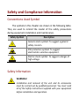
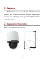
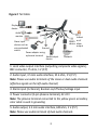
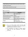
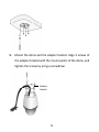
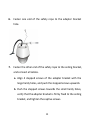
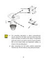
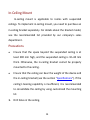
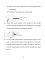
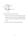
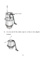
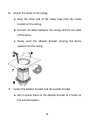
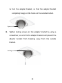
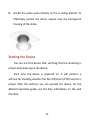
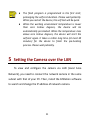
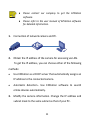
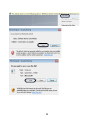
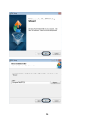
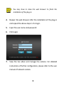
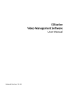
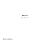
IPC640 Series
Indoor PTZ Dome IP Cameras
Quick Guide
Manual Version: P100 ‐20140120 © 2014, Zhejiang Uniview Technologies Co., Ltd. and its licensors All Rights Reserved No part of this manual may be reproduced or transmitted in any form or by any means without prior written consent of Zhejiang Uniview Technologies Co., Ltd. Notice The information in this manual is subject to change without notice. Every effort has been made in the preparation of this manual to ensure accuracy of the contents, but all statements, information, and recommendations in this manual do not constitute the warranty of any kind, express or implied. Technical Support [email protected] Environmental Protection This product has been designed to comply with the requirements on environmental protection. For the proper storage, use and disposal of this product, national laws and regulations must be observed. Safety and Compliance Information Conventions Used Symbol The symbols in this chapter are shown in the following table. They are used to remind the reader of the safety precautions during equipment installation and maintenance. Safety Symbol Description Generic alarm symbol: To suggest a general safety concern. ESD protection symbol: To suggest electrostatic‐sensitive equipment. Electric shock symbol: To suggest a danger of high voltage. Safety Information WARNING! Installation and removal of the unit and its accessories must be carried out by qualified personnel. You must read all of the Safety Instructions supplied with your equipment before installation and operation. Warnings: z
If the product does not work properly, please contact your dealer or the nearest service center. Never attempt to disassemble the camera yourself. (We shall not assume any responsibility for problems caused by unauthorized repair or maintenance.) z
This installation should be made by a qualified service person and should conform to all the local codes. z
Make sure the power supply voltage is correct before using the camera. z
Do not drop the camera or subject it to physical shock. z
Do not touch sensor modules with fingers. If cleaning is necessary, use a clean cloth with a bit of ethanol and wipe it gently. If the camera will not be used for an extended period of time, put on the lens cap to protect the sensor from dirt. z
Do not aim the camera lens at the strong light such as sun or incandescent lamp. The strong light can cause fatal damage to the camera. z
The sensor may be burned out by a laser beam, so when any laser equipment is being used, make sure that the surface of the sensor not be exposed to the laser beam. z
While shipping, the camera should be packed in its original packing. Caution: Fiber optic ports – optical safety. Never look at the transmit laser while the power is on. Never look directly at the fiber ports and the fiber cable ends when they are powered on. Caution: Use of controls or adjustments to the performance or procedures other than those specified herein may result in hazardous laser emissions. Regulatory Compliance FCC Part 15 This equipment has been tested and found to comply with the limits for digital device, pursuant to part 15 of the FCC Rules. These limits are designed to provide reasonable protection against harmful interference when the equipment is operated in a commercial environment. This equipment generates, uses, and can radiate radio frequency energy and, if not installed and used in accordance with the instruction manual, may cause harmful interference to radio communications. Operation of this equipment in a residential area is likely to cause harmful interference in which case the user will be required to correct the interference at his own expense. This product complies with Part 15 of the FCC Rules. Operation is subject to the following two conditions: 1.
This device may not cause harmful interference. 2.
This device must accept any interference received, including interference that may cause undesired operation. LVD/EMC Directive This product complies with the European Low Voltage Directive 2006/95/EC and EMC Directive 2004/108/EC. WEEE Directive–2002/96/EC The product this manual refers to is covered by the Waste Electrical & Electronic Equipment (WEEE) Directive and must be disposed of in a responsible manner. Contents 1 Overview ............................................................................... 2 2 Appearance Description ......................................................... 2 3 Precautions ............................................................................ 5 4 Installation ............................................................................ 7 Mounting the SD Card (Optional) ............................................ 7 Ceiling Mount ........................................................................... 9 In‐Ceiling Mount .................................................................... 14 Precautions ....................................................................... 14 Starting the Device ................................................................. 20 5 Setting the Camera over the LAN .......................................... 21 6 Accessing the Camera ........................................................... 23 System Requirement .............................................................. 23 Steps ...................................................................................... 24 i 1 Overview IPC640 indoor series are day & night PTZ dome network cameras. They are primarily designed to survey remote indoor scenarios, such as buildings, venues, gas stations, hotels, airports, and waiting rooms. 2 Appearance Description Figure 1 Size and Appearance (Unit: mm) 259
194
2 Figure 2 Tail Cable Display device
Audio monitor
Alarm input device such as voice activated Ground
switch
Power adapter using a phoenix terminal
Audio output device
Indicat
RS485 or of device alarm output
IP network
Network
1: Local video output interface (outputting composite video signals), BNC connector, 75 ohm, 1 V (P‐P) 2: Audio input, 3.5 mm audio interface, 35 k ohm, 2 V (P‐P) Note: Please use audio terminals of the mono or dual audio channels (effective signals on the left audio channel) 3: Alarm input (2‐channel), Boolean on/off value/voltage input 4: Power connector (3‐pin phoenix terminal), AC 24 V Note: The phoenix terminal connected to the yellow green secondary color cable is used in grounding 5: Audio output, 3.5 mm audio interface, 600 ohm, 2 V (P‐P) Note: Please use audio terminals of dual audio channels. 3 6: 10M/100M Base‐TX adaptive Ethernet electrical interface, RJ45 7: RS‐485 serial interface 8: Alarm output (1‐channel), relay output Table 1 Specifications Item Description Power AC 24V±25%, PoE Maximum power consumption 20 W Operating temperature –20°C to +50°C Operating humidity 10% to 90% (non‐condensing) Weight Camera: 3.2 kg In‐ceiling bracket: 1.4 kg z
z
This is an A‐level product, which may bring radio interference in surroundings. In this case, you need to adopt feasible anti‐interference solutions. The specifications are subject to changes without notice. For the latest information, see product datasheets. 4 3 Precautions z
Avoid squashing, shaking, or damping the device in transport, storage, and mounting. Keep away from vibration sources as much as possible during mounting. z
Use the power adapter (AC24V 3A) delivered with the device by the mounting package, or select a Power over Ethernet (PoE) device. Improper power adapters may damage the device. z
Verify that the power cable between the power adapter and the device is equal to or shorter than 1.5 m. If this power cable is longer than 1.5 m, the voltage of the device is lowered and the device frequently will be abnormal. If it is required to lengthen the power cable, lengthen the cable between the power adapter and the mains (220 V). z
Power off the device before moving it. During moving, exercise caution to avoid electric shock. Be aware that the device is powered once the power cable is connected to the mains. 5 z
When moving the device, do not hold the tail cable by hand for weight bearing. Otherwise, the cable connector of the device could be loosened. z
Do not cut off the tail cable for connection purposes. A bare tail cable may easily cause a short circuit, resulting in abnormality of or damage to the device. z
When connecting to an external interface, use an existing connection terminal, and ensure that the cable terminal (latch or buckle) is in good condition and properly fastened. Ensure that the cable is not tense during mounting, with a proper margin reserved to avoid poor port contact or loosening caused by shock or shake. z
Do not expose but well protect the tail end of the tail cable. Ensure that the tail cable area is waterproof, and avoid immersing the tail cable in accumulated water. z
Ensure that the high level signal of alarm input is lower than 5V DC when connecting to the alarm input interface. 6 z
Ensure that the device is stably mounted (especially when it is mounted on the wall or ceiling). Use the safety rope to prevent the device from falloff when mounting the camera. z
To keep the housing clean, do not remove the transparent protective film in the outer layer of the housing during mounting. After confirming that the mounting is complete, remove the transparent protective film before the device is started. z
It is common that static electricity exists on the housing. To avoid dust absorption caused by static electricity, it is recommended that you wipe the surface of the housing with ESD gloves after removing the transparent protective film. 4 Installation Mounting the SD Card (Optional) The SD card is located inside the device. To mount the SD card, you need to remove the housing. Hot plugging is not recommended after you insert the SD card. 7 For details about recommended SD card specifications, contact sales or technical support personnel. The SD card uses the FAT32 file system, and supports only one partition.
1.
Unscrew the housing by removing 3 inner hexagon screws along the housing edge. 2.
Insert the SD card into the slot and reinstall the housing. 8 Ceiling Mount You can mount the device when the wall and ceiling can bear common self‐tapping screws and the device weight (see the section "Specifications"). The ceiling bracket is attached with the device delivery. 1.
Mark positions of holes. Verify that holes on the wall align with the inner holes of the ceiling bracket. a. Lead cables to be connected out of wall holes. b. Mark positions of holes by referring to mount points of the ceiling bracket. Ceiling rack
Inner hole of the rack
2.
Drill holes (depth: about 30 mm) on the wall by using a drill bit of the diameter 6 mm or 6.5 mm. 9 3.
Mount the plastic rivets of self‐tapping screws, hammer the plastic rivets into the pilot holes, and verify that they are firm. 4.
Mount the ceiling bracket by using a screwdriver to fasten the self‐tapping screws through the bracket pilot holes to the ceiling. 10 5.
Mount the dome and the adapter bracket. Align 4 screws of the adapter bracket with the mount points of the dome, and tighten the screws by using a screwdriver. Adapter bracket
11 6.
Fasten one end of the safety rope to the adapter bracket hole. 7.
Fasten the other end of the safety rope to the ceiling bracket, and connect all cables. a. Align 4 stepped screws of the adapter bracket with the large hardy holes, and push the stepped screws upwards. b. Push the stepped screws towards the small hardy holes, verify that the adapter bracket is firmly fixed to the ceiling bracket, and tighten the captive screws. 12 Hardy holes(4)
Stepped screws(4)
Plastic film
Captive screw
z
z
The preceding description is about concealed‐wire mount, where the tail cable is led out of the top of the device and holes are drilled in the ceiling. To implement open‐wire mount, you need to remove a piece of plastic film on the device flank and implement cabling, as shown in the preceding figure. After connecting the tail cable, perform waterproof treatment for the tail cable by using waterproof tapes.
13 In‐Ceiling Mount In‐ceiling mount is applicable to rooms with suspended ceilings. To implement in‐ceiling mount, you need to purchase an in‐ceiling bracket separately. For details about the bracket model, see the recommended list provided by our company's sales department. Precautions z
Ensure that the space beyond the suspended ceiling is at least 300 mm high, and the suspended ceiling is 10–40 mm thick. Otherwise, the in‐ceiling bracket cannot be properly mounted to the ceiling. z
Ensure that the ceiling can bear the weight of the device and the in‐ceiling bracket (see the section "Specifications"). If the ceiling's bearing capability is insufficient, it is recommended to consolidate the ceiling by using customized the mounting kit. 1.
Drill holes in the ceiling. 14 a. Stick the hole positioning sticker of the in‐ceiling bracket in the ceiling. b. Cut a hole of the proper size on the ceiling. Hole positioning sticker
2.
Mount the inside bracket to the ceiling. Put the bracket inside the ceiling through the hole, and align the inner edge of the bracket with the inner edge of the hole. Inside bracket
3.
Fix the inside bracket and the outside bracket, align 2 screw holes on the outside bracket to hole positions on the inside bracket, fasten 2 screws by using a screwdriver, and verify that the inside bracket and the outside bracket have been fixed. 15 Outside bracket
4.
Mount the dome to the adapter bracket. a. Lead the tail cable of the dome through the adapter bracket or out of the top hole of the adapter bracket. Then, push the dome to the adapter bracket from bottom to top. b. Tighten 4 screws on the top by using a screwdriver. 16 Adapter bracket
5.
Fix one end of the safety rope to a hole on the adapter bracket. 17 6.
Mount the dome to the ceiling. a. Hang the other end of the safety rope onto the inside bracket on the ceiling. b. Connect all cables between the ceiling and the tail cable of the dome. c. Slowly push the adapter bracket carrying the dome upward into the ceiling. 1
2
3
7.
Fasten the adapter bracket and the outside bracket. a. Aim 3 square holes on the adapter bracket to 3 hooks on the outside bracket. 18 b. Turn the adapter bracket, so that the adapter bracket completely hangs on the hooks on the outside bracket. Square hole
8.
Tighten locking screws on the adapter bracket by using a screwdriver, so as to fix the adapter bracket and prevent the adapter bracket from breaking away from the outside bracket. Locking screws
19 9.
Buckle the plastic panel directly to the in‐ceiling bracket. To effectively protect the dome, expose only the transparent housing of the dome. Starting the Device You can start the device after verifying that the mounting is proper and powering on the device. Each time the device is powered on, it will perform a self‐test for checking whether the Pan/Tilt/Zoom (PTZ) function is proper. After the self‐test, you can operate the device. For the detailed operation guide, see the help information on the web interface. 20 z
z
The flash program is programmed in the first start, prolonging the self‐test duration. Please wait patiently. When you restart the device, the self‐test will be quick.
When the working environment temperature is lower than zero Celsius degrees, the device will be automatically pre‐heated. When the temperature rises above zero Celsius degrees, the device will start the self‐test again. It takes a rather long time (at most 30 minutes) for the device to finish the pre‐heating process. Please wait patiently. 5 Setting the Camera over the LAN To view and configure the camera via LAN (Local Area Network), you need to connect the network camera in the same subnet with that of your PC. Then, install the EZStation software to search and change the IP address of network camera. 21 z
z
Please contact our company to get the EZStation
software. Please refer to the user manual of EZStation software for detailed information. 1.
Connection of network camera and PC. 2.
Obtain the IP address of the camera for accessing via LAN. To get the IP address, you can choose either of the following methods: z
Use EZStation as a DHCP server that automatically assigns an IP address to the connected camera. z
Automatic detection:Use EZStation software to search online devices automatically. 3.
Modify the camera information. Change the IP address and subnet mask to the same subnet as that of your PC. 22 4.
Enter the IP address of camera in the address field of the web browser to view the live video. z
z
The default IP address is “192.168.0.13”. The default
user name is “admin”, and password is “admin”. For accessing the camera from different subnets, please set the gateway for the camera after you log in. 6 Accessing the Camera System Requirement Item Requirements Operation System Microsoft Windows8/Windows7/Windows XP (32‐bit or 64‐bit). Microsoft Windows7 is recommended. CPU 2.0GHz or higher, dual‐core. Intel i3 CPU or above are recommended. Memory At least 1GB. 2GB (or higher) is recommended. Graphic card At least 128MB display memory. Mainstream discrete graphics with more than 1GB display memory are recommended. The hardware should support DirectX9.0c. Note: make sure that the latest driver is installed on 23 Item Requirements graphic card. Sound card Essential. Note: the intercom and voice broadcast require the latest driver on sound card. Network card Gigabit Ethernet network cards (or higher) are recommended. Display definition z
z
Least: 1024*768 Ideal: 1440*900 Steps 1.
Open the web browser. 2.
In the browser address bar, input the IP address of the network camera, e.g., 192.168.0.13 and press the Enter key to enter the login interface. 3.
Install the plug‐in before viewing the live video and managing the camera. Please follow the installation prompts to install the plug‐in, as shown in the figures. 24 25 26 27 You may have to close the web browser to finish the installation of the plug‐in. 4.
Reopen the web browser after the installation of the plug‐in and repeat the above steps 1‐2 to login. 5.
Input the user name and password. 6.
Click Login. 7.
View the live video and manage the camera. For detailed instructions of further configuration, please refer to the user manual of network camera. 28 BOM: 3101C033