1
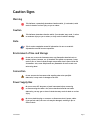
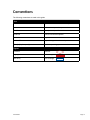
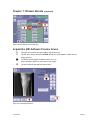
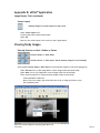
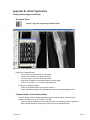
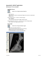
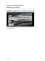
MarkIIG™ RapidStudy™ User Guide MarkIIG RapidStudy™ User Guide Version 1.0 Part Number 74-156 August 2010 Copyright Notice Copyright © 2010 Sound-Eklin™, 5817 Dryden Place, Suite 101, Carlsbad, CA 92008, USA. All Rights Reserved. This manual shall not wholly or in part, in any form or by any means, electronic, mechanical, including photocopying, be reproduced or transmitted without the authorized written consent of Sound-Eklin™. This guide has been produced to assist in providing instructions for the Sound-Eklin™ MarkIIG™ RapidStudy™ product. Every effort has been made to make the information in this guide as accurate as possible. The authors of this guide shall have neither liability nor responsibility to any person or entity with respect to any loss or damages in connection with or arising from the information contained in this guide. Trademarks Sound-Eklin™ and RapidStudy™ are trademarks of Sound-Eklin™. Any additional software products named in this document are claimed as trademarks or registered trademarks of their respective companies. Sound-Eklin™ Page ii Please Note 1. This product is intended for Veterinary use only (not for human use). 2. Roentgenography, image processing, reading of image, and storage of data must be performed in accordance with the law of the state/country where the product is being used. 3. The user is responsible for maintaining the privacy of image data. 4. The user is responsible for the use and maintenance of the product. We suggest that a member of the user’s staff be designated as being in charge of maintenance so as to ensure that the product is kept in a safe and good condition. Also, veterinary medical products must be used only by a qualified person. 5. In no event will Sound-Eklin™ be liable for direct or indirect consequential damage arising out of the use of this product. Sound-Eklin™ will not be liable for loss of image data due to any reason. 6. Sound-Eklin™ reserves the right to change the specifications, configuration and appearance of the product without prior notice. 7. Do not make any changes or modifications to the equipment unless otherwise specified in the manual. 8. The products are not fault tolerant and are not designed, manufactured or intended for use or resale as on-line control equipment in hazardous environments requiring fail safe controls, such as in the operation of nuclear facilities, aircraft navigation or aircraft communication systems, air traffic control life support, or weapons systems (“high risk activities”). Sound-Eklin™, on behalf of itself and the manufacturers or suppliers of the products, specifically disclaims any express or implied warranty of fitness for such high risk activities. Buyer represents and warrants that it will not use, or knowingly directly or indirectly distribute or resell products for such high risk activities. Sound-Eklin™ Page iii General Safety Information Follow the safety instructions in this manual and all warnings and cautions printed on the warning labels. Ignoring such cautions and warnings while handling the product may result in injury or accident. Be sure to read and fully understand the manual before using this product. Note: Digital Radiography exposes you to the same radiation as conventional radiography. Always practice radiation safety when using this product. Keep this manual for further reference. Sound-Eklin™ Page iv Caution Signs Warning This indicates a potentially hazardous situation which, if not heeded, could result in death or serious injury to you or others. Caution This indicates hazardous situation which, if not heeded, may result, in minor or moderate injury to you or others, or may result in machine damage. Note This is used to emphasize essential information. Be sure to read this information to avoid incorrect operation. Environment of Use and Storage Do not use or store the instrument near any flammable chemicals such as alcohol, thinner, benzene, etc. If chemicals are spilled or evaporate, it may result in fire or electric shock through contact with electric parts inside the instruments. Also, some disinfectants are flammable. Be sure to take care when using them. Connection Do not connect the instrument with anything other than specified. Otherwise, it may result in damage to the unit. Power Supply Box Be sure to turn OFF the power of each instrument before connecting or disconnecting the cables. Also, do not handle them with wet hands. Otherwise, you may get an electric shock that may result in death or serious injury. Be sure to hold the plug or connector to disconnect the A/C power cables. If you pull the cable, the core wire may be damaged, resulting in fire or electric shock. Sound-Eklin™ Page v Caution Signs (continued) Do not cut or process the A/C power cables. Also, do not place anything heavy, including the instrument on it, step on it, pull it, bend it, or bundle it. Otherwise, the cable may be damaged, which may result in fire or electric shock. Because the instrument’s cable is long, take care so cables do not get tangled during use. Also, be careful not to get your feet caught in the cable. Do not turn ON the system power when condensation is formed on the instrument. Otherwise, it may result in fire or electric shock. Handling Never disassemble or modify the product as it may result in fire or electric shock. Also, since the instrument incorporates parts that may cause electric shocks and other hazardous parts, touching them may cause death or serious injury. Do not hit or drop the instrument. The instrument may be damaged if it receives a strong jolt, which may result in fire or electric shock if the instrument is used without it being repaired. Disposal of the Unit This instrument incorporates lead, which may pollute the environment if the instrument is abandoned. Please send the instrument to Sound-Eklin™ for proper disposal. When Problem Occurs Immediately turn OFF the power of each instrument, unplug the power cable for the AC outlet, and contact Sound-Eklin™: when there is smoke, odd smell or abnormal sound; when liquid has been spilled into the instrument or a metal object has entered through an opening: when the instrument has been dropped and it is damaged. Maintenance and Inspection The instrument must be repaired by a qualified engineer only. If it is not repaired properly, it may cause fire, electric shock, or accident. For safety reasons, be sure to inspect the instrument before using it. Sound-Eklin™ Page vi Conventions The following conventions are used in this guide: Text Bold Specific button on the touch or computer screen. Italics Reference to repeated steps or actions. “Bold” Example user input information. Underline Used for notational emphasis. <Ctrl> Keystroke. <Alt> + <F4> Keystrokes typed simultaneously. [Start] > [My Computer] Windows operating system menu selections. Figures Click box Red oval. Highlight box Red rectangle. Text entry Blue rectangle. Sound-Eklin™ Page vii Table of Contents MarkIIG™ RapidStudy™ User Guide Copyright Notice............................................................................................... ii Trademarks..................................................................................................... ii Please Note.....................................................................................................iii General Safety Information..................................................................................iv Caution Signs .................................................................................................. v Warning ......................................................................................................... v Caution ......................................................................................................... v Note ............................................................................................................. v Environment of Use and Storage .......................................................................... v Connection ..................................................................................................... v Power Supply Box ............................................................................................. v Handling.........................................................................................................vi Disposal of the Unit ..........................................................................................vi When Problem Occurs .......................................................................................vi Maintenance and Inspection ................................................................................vi Caution Signs...................................................................................................vi Conventions.................................................................................................... vii rev082010 Sound-Eklin™ Page viii Table of Contents Chapter 1: Introduction to the MarkIIG™ Features......................................................................................................... 1 Chapter 2: Start-up and Shutdown Procedures...................................................................................................... 2 Start-up.......................................................................................................... 2 Connect the sensor panel cable to the MarkIIG™ power supply box ............................... 2 Connect the synchronization cable........................................................................ 3 Shut-down....................................................................................................... 4 Disconnect Cables for Transport........................................................................... 4 Disconnect all cables in reverse order.................................................................... 4 Chapter 3: Navigating Between Applications Hot Keys......................................................................................................... 5 DR and eFilm™.................................................................................................. 5 Troubleshooting................................................................................................ 6 Chapter 4: Image Acquisition Entering Patient Information................................................................................ 7 Acquiring Image................................................................................................ 9 Preview the Image............................................................................................ 9 Evaluate the Image............................................................................................ 9 Chapter 5: Processing the Image Image Quality Assurance.................................................................................... 12 Adjusting Images.............................................................................................. 12 Look Up Table — LUT................................................................................... 13 Laplacian Enhancement — LAP. ENHANCE.......................................................... 14 Position.................................................................................................... 15 Annotation................................................................................................ 16 Adjust Trim............................................................................................... 17 Adjust ROI (Region of Interest)........................................................................ 18 View Enlarged Image.................................................................................... 19 Completion of Image Quality Assurance............................................................ 19 rev082010 Sound-Eklin™ Page ix Table of Contents Chapter 6: Transferring Images from the MarkIIG™ Setting the Destination......................................................................................20 Setting the Destination (continued)...................................................................... 21 Setting the Destination (continued)......................................................................22 Transferring Images During Acquisition..................................................................22 Transferring Images Acquired Remotely.................................................................23 Chapter 7: Wireless Remote To Setup........................................................................................................24 Acquisition (DR) Software Main Screen..................................................................24 Acquisition (DR) Software Preview Screen..............................................................25 Auto Display Magnify Feature..............................................................................26 Scripting Off — Preview Image Time (sec) Set to Zero (Ø)...........................................26 Scripting On — Preview Image Time (sec) Set to One (1).............................................26 Scripting On — Preview Image Time (sec) Set to One (1) (continued).............................. 27 Chapter 8: Customizing MarkIIG™ Settings Study Info......................................................................................................28 To Modify the Study Information.....................................................................28 Editing Exposure Mode Parameters.......................................................................30 Edit the Body Part Button Names....................................................................30 Edit the DICOM Series Description................................................................... 31 Copy the Body Part Button to Save as New Menu Buttons...................................... 31 Change the Order and Location of the Body Part Buttons...................................... 32 Move, Add or Change a Body Parts Tab............................................................. 32 Change the Image Processing (IP) and Lap Enhance Parameters...............................34 Annotation................................................................................................34 Sleep Mode..................................................................................................... 36 Changing the MarkIIG™ Password..........................................................................36 Setting Date and Time....................................................................................... 37 rev082010 Sound-Eklin™ Page x Table of Contents Chapter 9: MarkIIG™ Maintenance Care and Storage of Sensor Panel and Cable............................................................38 Calibration Procedures......................................................................................38 Chapter 10: Troubleshooting Image Acquisition.............................................................................................40 No Exposure or Unable to Make Exposure...............................................................40 Synchronization Issues......................................................................................40 Image Artifacts................................................................................................ 41 Sensor Panel Error........................................................................................... 41 Image Transfer................................................................................................ 41 DICOM connect error (-502)................................................................................ 41 Chapter 12: Specifications Sensor Panel................................................................................................... 42 System.......................................................................................................... 42 rev082010 Sound-Eklin™ Page xi Table of Contents Appendix A: Digital Radiography Technique Charts Portable 80/15................................................................................................ 43 Portable 80/15 (continued).................................................................................44 Portable 100/30...............................................................................................45 Gantry.......................................................................................................... 47 Appendix B: eFilm™ Application Opening eFilm™ on the MarkIIG™ Laptop................................................................ 49 Appendix B: eFilm™ Application (continued)............................................................50 Opening eFilm™ on Eklin RapidView™ Workstations...................................................50 View a Study..............................................................................................50 Search Study Manager List............................................................................. 51 Search Owners Last Name............................................................................. 51 Search Patient ID........................................................................................ 51 Search Dates.............................................................................................. 51 Burn CD......................................................................................................... 52 Copy an Entire Study.................................................................................... 52 Copy Multiple Studies in Sequence................................................................... 53 Copy Multiple Studies Not in Sequence............................................................. 53 Copy Selected Images...................................................................................54 Image Display Tools . ........................................................................................ 55 Toggle Survey/Explode Mode.......................................................................... 55 Window/Level (Right Mouse).......................................................................... 55 Magnification (Left Mouse).............................................................................56 Pan (Left mouse) and Zoom (Right mouse).........................................................56 Toggle Overlay........................................................................................... 57 Add User Annotation (Left Mouse)...................................................................58 Scrapbook................................................................................................. 59 Screen Layout............................................................................................60 rev082010 Sound-Eklin™ Page xii Table of Contents Appendix B: eFilm™ Application (continued) Viewing Study Images........................................................................................60 Viewing Previous or Next: Studies or Series.......................................................60 Thumbnail Panel......................................................................................... 61 Compare Studies From Different Dates.............................................................. 61 Image Orientation Tools..................................................................................... 62 To Toggle Image Orientation............................................................................... 62 Flip Horizontal........................................................................................... 62 Flip Vertical............................................................................................... 62 Rotate 90 Degrees Counter-Clockwise.............................................................. 62 Rotate 90 Degrees Clockwise......................................................................... 62 Invert....................................................................................................... 62 Measurement Tools........................................................................................... 62 Arrow (Right Mouse).................................................................................... 62 Line (Right Mouse)....................................................................................... 63 Show Angles.............................................................................................. 63 Clear Measurement Tool...............................................................................64 Elliptical Tool.............................................................................................64 Calibrate...................................................................................................64 Image Stitching Tool.........................................................................................64 Accustitch......................................................................................................64 Appendix C: Technical Support Shipping Address.............................................................................................. 67 Technical Support............................................................................................ 67 Website......................................................................................................... 67 rev082010 Sound-Eklin™ Page xiii Chapter 1: Introduction to the MarkIIG™ Figure 1-1: MarkIIG™ RapidStudy™ Features The MarkIIG™ features a lightweight laptop offering total system control, eFilm™ viewing software and redundant storage of up to 3000 images. Everything is contained in a ballistic nylon carrying case and is easily transported. Sound-Eklin™ Page 1 Chapter 2: Start-up and Shutdown Procedures Start-up Place the MarkIIG™ on a sturdy surface. Then connect the sensor panel cable. Connect the sensor panel cable to the MarkIIG™ power supply box : 1. Align large connector with port on rear of MarkIIG™ power supply box. Push straight in until firmly seated. Finger tighten. Figure 2-1: To Power Supply Box Connection The MarkIIG™ is designed to allow the sensor panel cable to remain connected to the power supply box at all times (recommended). If the sensor panel cable has been disconnected follow the steps above. Figure 2-2: To Sensor Panel Connection Sound-Eklin™ Page 2 Chapter 2: Start-up and Shutdown Procedures (continued) 2. Connect the sensor panel cable to the sensor panel. Align the red dot on the small connector with the red dot on the sensor panel. Push straight in until a click is heard. The click will indicate the cable is connected correctly. Always connect the sensor panel cable to the MarkIIG™ power supply box before any other cable. Never disconnect this cable when the MarkIIG™ power supply is powered on. Connect the synchronization cable Figure 2-3: Synchronization Cable Connections 1. Connect the synchronization cable to the MarkIIG™ power supply box: Remove the synchronization cable cap. Align the red dot on the synchronization cable connector with the red dot on the synchronization cable connection on the MarkIIG™ power supply box. Push straight in until a click is heard. The click indicates the cable is connected correctly. 2. Connect the synchronization cable to the synchronization box located on the x-ray generator. Align the synchronization cable connector with the pins on the synchronization box connector. Tighten the thumb screw connector finger tight. 3. Connect the x-ray generator to a power source. 4. Connect the power cable to the MarkIIG™ power supply box. 5. Connect the MarkIIG™ power cable to a power source. 6. Connect the cross-over cable to the MarkIIG™ power supply box and the laptop. 7. Start the MarkIIG™ power supply box by depressing the power button on the front of the console. 8. To start the laptop, open the laptop. Press the ON/OFF button to turn the laptop on. Sound-Eklin™ Page 3 Chapter 2: Start-up and Shutdown Procedures (continued) Shut-down Power down the MarkIIG™. Depress the power button on the MarkIIG™ laptop momentarily. This will cause the laptop to close all open software and shutdown. Disconnect Cables for Transport Disconnect all cables in reverse order. 1. Disconnect the cross over cable. 2. Disconnect the synchronization cable. 3. Disconnect the MarkIIG™ power cable from the power source. 4. Disconnect the power cable from the MarkIIG™ power supply box The MarkIIG™ is designed to allow the sensor panel cable to remain connected to the power supply box at all times (recommended). 5. If the sensor panel cable is disconnected it should be disconnected last. Wait 15 seconds to disconnect the sensor panel cable after turning off the MarkIIG™ power supply box. See Figure 2-1: To Power Supply Box Connection and Figure 2-2: Synchronization Cable Connections. If wireless devices (wireless mouse or wireless remote) have been used, disconnect receiving devices from USB ports and store with appropriate device. Failure to disconnect wireless receiving devices before transport may result in damage to receiving device or USB port. Sound-Eklin™ Page 4 Chapter 3: Navigating Between Applications Hot Keys When using the wireless mouse, insert the wireless receiver into the USB port. (The receiving device is stored in the bottom of the wireless mouse.) DR and eFilm™ When on the main screen in either the DR (acquisition software) or eFilm™ (viewing software) application. Hold the left mouse button and click right button to toggle between applications. Hold Click Figure 3-1: Toggle Between DR and eFilm The actual unit shipped may differ from the image depicted. Click Hold Figure 3-2: Activate On-screen Keyboard Figure 3-3: Toggle On-Screen Keyboard Hold the right mouse button and click the left to activate the on-screen keyboard. Close on-screen keyboard using the mouse key combination or click on the “x”. The left mouse button is still active, therefore it is better to move to an unused portion of the screen to avoid inadvertently activating a control. Sound-Eklin™ Page 5 Chapter 3: Navigating Between Applications (continued) Troubleshooting If the system does not respond to wireless device: 1. Check receiver is installed in USB port. 2. Check receiver has green light. 3. Check batteries are installed. 4. Check batteries are installed correctly. 5. Check batteries have charge. Sound-Eklin™ Page 6 Chapter 4: Image Acquisition Entering Patient Information Figure 4-1: Main Screen > PATIENT Figure 4-2: Patient Information Screen On the Main screen, select PATIENT. On the Patient Information Screen, enter: Required information: 1. Name — Enter the owner’s full name (lastname firstname). Names should be entered in a consistent manner. It is suggested that all capital letters be used. The maximum length is 63 alphanumeric characters.. 2. ID — Enter patient identification (maximum length is 32 alphanumeric characters). Each patient should be assigned a unique identifier. In equine radiography, this is usually the patient’s name. Optional information: 1. Choose the patient’s sex by selecting MALE, FEMALE, or OTHER. 2. Birth – Enter the patient’s birth date. The patient’s age will be automatically calculated if the month, day, and year are entered as follows: Month – 2 digits (i.e., 01 for January) Day – 2 digits (i.e., 01 for the 1st day of the month) Year – 4 digits (i.e., 2005). System will not calculate age if date format is invalid. Sound-Eklin™ Page 7 Chapter 4: Image Acquisition Entering Patient Information (continued) Figure 4-3: Patient Information Screen > STUDY INFO Figure 4-4: STUDY INFO Screen 3. Select STUDY INFO. Select the desired study information from the screen using the drop down lists. Select OK to save the study information. Alternatively, select CANCEL to return to the Patient Information screen without saving any changes to the study information. Select OK on the Patient Information screen to return to the Main screen. If incorrect data was entered, select PATIENT to make changes. Study information may be changed before the study is ended by selecting PATIENT on the main screen. Permanent changes cannot be made after the study is ended. Refer to Chapter 8, Customizing MarkIIG™ Settings > Study Info to customize Study Info Menus. Sound-Eklin™ Page 8 Chapter 4: Image Acquisition (continued) Acquiring Image Figure 4-5: Initial Acquisition Screen 1. Select the body part to be examined. 2. Select the radiographic view. 3. Set the technique on the x-ray machine and make the exposure. Preview the Image A preview of the acquired image will appear on the screen within 3-5 seconds after exposure. The preview screen allows you to evaluate the image for appropriate positioning, motion, and technique. Evaluate the Image REX Figure 4-6: Initial Image Capture The number in the lower right corner of the image is the reached exposure (REX) number. (See Figure 4-6 above.) Sound-Eklin™ Page 9 Chapter 4: Image Acquisition Evaluate the Image (continued) The REX value indicates the relative number of x-ray photons that reached the sensor panel. An acceptable range for the REX number on the MarkIIG™ is 200-800 with 300-600 being the optimal range. • REX values less than 200 may be objectionably grainy when zoomed and should be repeated. • REX values in excess of 800 will not affect image quality, but indicate more exposure was used than is necessary. With very high REX values (>2000) the panel may saturate and be unable to record the anatomy. When this occurs a black ghost image may appear over the thinner parts of the field of view. • The number that appears on the initial preview screen is an average value for the entire acquisition area of the sensor panel. • The REX number will change when the region of interest (ROI) or Brightness and Contrast is adjusted. • The region of interest may be adjusted in the QA screen. 1. If the image is acceptable, select OK and continue the study. 2. If the image is not acceptable, select RETAKE. Select OK in the dialogue box to retake the image. The unit will reset to allow immediate retake of the image in the same radiographic view. Retake image for: • Low REX value or noisy (grainy) image • Incorrect positioning • Movement Figure 4-7: Retake Image Capture Sound-Eklin™ Page 10 Chapter 4: Image Acquisition Evaluate the Image (continued) 3. If the image is not acceptable due to mislabeling, select REJECT. Select OK in the lower right-hand corner of this screen. The main screen will appear allowing you to select another radiographic view. Images that have been rejected by selecting RETAKE or Reject are not permanently deleted. The Reject button is a toggle button. Select the Reject button again to restore the image to the study. Images may also be restored to the study by selecting the MULTI VIEW button. This will display a thumbnail of all images in the current study. Rejected images will have an “X” next to them. To restore a rejected image in the multiview screen, select the image and select the Reject button to toggle it to off. The image will have a number beside it instead of an X when it has been restored to the study. See Figures 4-8c: Restore Image Capture. Figure 4-8a: Rejected Image Capture Figure 4-8b: Restoring An Image Capture Figure 4-8c: Restored Image Capture Sound-Eklin™ Page 11 Chapter 5: Processing the Image Image Quality Assurance All body part (radiographic view) buttons are preset at the factory to yield consistent results with a wide variety of x-ray machines and techniques. These QA tools are very powerful and have a dramatic effect on image quality. These settings may be interactively altered on each image if desired. However, since the changes are permanent we do not recommend changing the default settings until you have sufficient experience with your new digital system, and are sure you want to permanently make changes. Any changes to the defaults should be done systematically for every view of that anatomical area. Indiscriminately changing the default settings can result in wide swings in image quality from view to view even when using the same radiographic technique. It is recommended that any changes to the preset buttons be made with the support of a Sound-Eklin™ Service Representative. Adjusting Images An image that is too light or too dark does not require a retake. Adjust the image using the steps and tools outlined below. Figure 5-1: Initiating QA 1. Select QA. 2. Then select the desired tab: LUT, LAP. ENHANCE., POSITION, or ANNOTATION. Sound-Eklin™ Page 12 Chapter 5: Processing the Image Image Quality Assurance (continued) Figure 5-2: LUT tab Look Up Table — LUT The gray scale curve used to display the image is modified using the lookup table (LUT). Any changes in these parameters are immediately reflected in the displayed image. • Set the BRIGHTNESS of the image between 1 and 29. The value on the left is the saved setting. The value on the right is the current setting which changes when the buttons are selected. Changing the brightness setting will change the brightness of the whole image. • Set the image CONTRAST between 1 and 29. The value on the left is the saved setting. The value on the right is the current setting, which changes when the buttons are selected. Changing the contrast setting will change the contrast of the whole image. • Select OK to save the changes. • If the new parameters are to be saved as the default select the small arrow in the bottom middle of the QA screen and SAVE PARAM to save the new parameters for the exposure modes as default. These parameters cannot be saved as default if the image has been accessed from the study list. Sound-Eklin™ The system password must be entered to save changes. Contact Sound-Eklin™ Technical Support if you forget this password. Page 13 Chapter 5: Processing the Image Image Quality Assurance (continued) Figure 5-3: LAP. ENHANCE. tab Laplacian Enhancement — LAP. ENHANCE. Laplacian Enhancement is the image processing algorithm and allows the user to enhance the image. The actual raw data changes as the DYNAMIC RANGE and EFFECT are modified. Set the dynamic range of the image between 1 and 20 (the typical range is between 1 and 5). This controls the spread of pixel values. A lower setting effectively subtracts exposure from over exposed areas and adds to under exposed areas. The value on the left is the saved setting. The value on the right is the current setting, which changes when the buttons are selected. Set the EFFECT of the image between 1 and 20 (the typical range is between 12 and 20). Effect enhances the contrast of the image. The value on the left is the saved setting. The value on the right is the current setting, which changes when the buttons are selected. Select OK to save the changes. If the new parameters are to be saved as the default, select the small arrow in the bottom middle of the QA screen and SAVE PARAM. These parameters cannot be saved as default if the image has been accessed from the study list. The system password must be entered to save changes. Contact Technical Support if you forget this password. Sound-Eklin™ Page 14 Chapter 5: Processing the Image Image Quality Assurance (continued) Figure 5-4: Position tab Position The position of the image is dependent on how the sensor panel is held relative to the patient. The position may be adjusted by selecting the POSITION tab. Figure 5-5: Orientation Pop-up Figure 5-6: Orientation Corrected • Select the orientation button. The image may be flipped horizontally or vertically or rotated 90 or 180 degrees clockwise or counterclockwise. Select OK to change the image orientation and select OK to apply the changes. • If the new parameters are to be saved as the default, select the small arrow in the bottom middle of the QA screen and SAVE PARAM. These parameters cannot be saved as default if the image has been accessed from the study list. • The system password must be entered to save changes. Contact Sound-Eklin™ Technical Support if you forget this password. Sound-Eklin™ Page 15 Chapter 5: Processing the Image Image Quality Assurance (continued) The Left and Right markers provided by the digital software are an overlay. Exercise care when utilizing the ‘flip’ feature as the image will be ‘flipped’ behind the overlay. This may lead to incorrectly marked images. Conventional lead markers may be placed on the sensor panel to ensure the image is marked correctly. Figure 5-7: Annotaion tab Annotation The annotation position for "Exposure Annotation" can be changed by selecting the respective buttons. • Exposure Anno. contains the L/R marker. • Annotation1 contains the patient information. • Annotation2 contains the practice information. Select OK to apply the changes. If the new parameters are to be saved as the default, select the small arrow in the bottom middle of the QA screen and SAVE PARAM. These parameters cannot be saved as default if the image has been accessed from the study list. The system password must be entered to save changes. Contact Sound-Eklin™ Technical Support if you forget this password. Sound-Eklin™ Page 16 Chapter 5: Processing the Image Image Quality Assurance (continued) Figure 5-8: Adjust Trim Figure 5-9: Select Area of Interest Adjust Trim When the button reads ADJUST TRIM, the image may be trimmed or cropped by clicking on the screen to create a box around the area of the image the user wishes to keep. Click the screen in opposing corners over the area of interest. A red border will appear around the selected area. The Green box around the image is an auto-crop feature in the software. The radiation dose is detected by the software. Only the area inside the Green box will be transferred to the workstations and/or a RapidStore™ PACS server. If the image is cropped in error, select the Reset button to reset the image to the original settings before selecting the OK button. The ADJUST TRIM button is a toggle button. Select the ADJUST TRIM button to toggle to ADJUST ROI. Sound-Eklin™ Page 17 Chapter 5: Processing the Image Image Quality Assurance (continued) Figure 5-10: Adjust ROI Figure 5-11: Selected ROI Adjust ROI (Region of Interest) Select ADJUST TRIM. This will toggle to ADJUST ROI. • When the button reads ADJUST ROI, the region of interest may be adjusted for brightness and contrast. • Select the anatomical area of interest by clicking the screen in opposing corners. A pink border will appear around the selected area. The brightness and contrast will be optimized to display the selected region of interest. Figure 5-11: Selected ROI Sound-Eklin™ Page 18 Chapter 5: Processing the Image Image Quality Assurance (continued) Completion of Image Quality Assurance Figure 5-12: MAG View Enlarged Image Select MAG. or QA-MAG. The image will be displayed on the full screen. Select CLOSE to exit and return to the QA screen. Completion of Image Quality Assurance Select OK to accept changes and return to the image preview screen. Sound-Eklin™ Page 19 Chapter 6: Transferring Images from the MarkIIG™ Images are automatically transferred from the MarkIIG™ acquisition software to eFilm™ when END STUDY button or the SEND button is depressed. Images may also be transferred to additional RapidView™ workstations or to a RapidStore™ PACS server. The study must be transferred to a RapidStore™ PACS server or burned onto a CD at the earliest opportunity to ensure adequate back-up. In a clinical scenario, a copy of the study may be sent to RapidView™ workstations and the RapidStore™ PACS server. Setting the Destination 1. Select SYSTEM. Figure 6-1: SYSTEM on Main Screen 2. Select SETUP MENU. Figure 6-2: SYSTEM > SETUP MENU Sound-Eklin™ Page 20 Chapter 6: Transferring Images from the MarkIIG™ Setting the Destination (continued) 3. Select DESTINATION. 4. Select STORAGE. Figure 6-3: DESTINATION tab 5. Select the desired destinations. RapidStore™ specifies a RapidStore™ PACS server as a destination. eFilm™ local specifies the integrated PACS viewer eFilm™ as a destination. • Select the buttons to turn them on or off. eFilm™ local should always be turned on. • Turn the RapidStore™ destination on when the MarkIIG™ is connected to the LAN (local area network). The RapidStore™ destination should be turned off when acquiring images remotely. • Select EXIT after setting the appropriate destinations on or off. Figure 6-4: Destination tab > Storage Sound-Eklin™ Page 21 Chapter 6: Transferring Images from the MarkIIG™ Setting the Destination (continued) Only two storage destinations may be used at one time. If two storage destinations are to be used, only these combinations can be used. The names STORAGE3 and STORAGE4 can be modified to reflect additional destinations. RapidStore and eFilm local RapidStore and STORAGE4 STORAGE3 and eFilm local STORAGE3 and STORAGE4 Transferring Images During Acquisition 1. Ensure the appropriate destinations are turned on. (Refer to the previous section, Setting the Destination) 2. Select OK on the Image Preview screen to return to the main screen. 3. Select SEND to send individual images to the chosen destinations. 4. Select END STUDY when image acquisition is complete. This will send all the images acquired in the study to the chosen destinations. Figure 6-5: END STUDY The study should be ended immediately upon completion by selecting the END STUDY button. This will prevent images from a different patient being added to the study in error. Sound-Eklin™ Page 22 Chapter 6: Transferring Images from the MarkIIG™ (continued) Transferring Images Acquired Remotely The MarkIIG allows you to transfer images acquired remotely to a RapidStore™ PACS Server or to a RapidView™ Workstation using eFilm™. 1. Connect the network cable to the port on the MarkIIG™ laptop and to the network port (or switch). 2. Toggle to eFilm™ Workstation software. With the acquisition software in the main screen use the Hot Key feature to toggle to eFilm™. • Depress and hold down the left side of the mouse. • Click the right side of the mouse. • Repeat steps a and b to toggle between eFilm™ and acquisition software. 3. In eFilm™ choose the studies to be transferred to the RapidStore™ PACS server or RapidView™ Workstation from the Study Manager List. 4. Select Send. 5. Select the appropriate destination in the popup window. 6. DO NOT check the encrypt box. 7. Select Send. Figure 6-6: eFilm™ Study Manager Sound-Eklin™ Figure 6-7: eFilm™ Select Destination Pop-up Page 23 Chapter 7: Wireless Remote The USB wireless remote with laser pointer is used to capture images while in the acquisition (DR) software. The buttons on the unit have different functions depending on the current screen. To Setup 1. Install the batteries in the wireless remote. 2. Insert USB receiver into USB port. The unit is plug-and-play, no software download or installation is required. For first time use, unit will take a few minutes to load. Figure 7-1: Wireless Remote The actual unit shipped may differ from the image depicted. For ease of storage and to reduce risk of loss the remote can be attached to the MarkIIG™ unit with the Velcro® from the accessories pack. Do not stare into or point the beam at another person. The USB receiver is stored in the back of the wireless remote. Acquisition (DR) Software Main Screen Sound-Eklin™ Press the right arrow button to select the next Body part button. This button will move sequentially through the body part buttons. Press the left arrow button to select the previous body part button. The square button has no function on this screen. The red dot button operates the laser pointer. Page 24 Chapter 7: Wireless Remote (continued) Figure 7-2: Select Next or Previous Body Part Acquisition (DR) Software Preview Screen The right arrow button functions as OK or typical enter key. The left arrow button will select RETAKE and the unit will prepare to retake the last image captured. The square button toggles the Reject button on or off. Select the square button to reject the current image. The red dot button operates the laser pointer. Figure 7-3: Preview Page Selections Sound-Eklin™ Page 25 Chapter 7: Wireless Remote (continued) Auto Display Magnify Feature With the Auto Display Magnify feature on the image will automatically be displayed in high resolution (1280x1024). To turn on the Auto Display Magnify feature: 1. On main screen select SYSTEM. 2. On system screen select SETUP MENU. 3. On system information screen select ADMINISTRATOR SETUP. 4. On administrator setup screen select MAGNIFY SETTING. 5. On magnify setting screen toggle Auto Display setting to DISPLAY. 6. Select EXIT and OK. 7. Select OK when asked “Do you want to change the current settings?” 8. Select EXIT to return to main screen. Auto display magnify can be used with or without scripting. With scripting off, use the wireless remote to select the next body part button. Scripting Off — Preview Image Time (sec) Set to Zero (Ø) Right arrow button will close magnified screen and return to preview screen. The image may be accepted, rejected or retaken [See Chapter 4. Acquisition (DR) Software Preview the Image]. Select right arrow again to return to main screen. Left arrow button will reset screen to original magnification. The square button will increase magnification. The red dot button operates the laser pointer. Scripting On — Preview Image Time (sec) Set to One (1) When the Preview Image Time (sec) is set at one (1) the system will advance to the next body part button, there is no retake option. The right arrow button will close magnified screen and return to main screen. The left arrow button will reset screen to original magnification. The square button will increase magnification. The red dot button operates the laser pointer. Sound-Eklin™ Page 26 Chapter 7: Wireless Remote Scripting On — Preview Image Time (sec) Set to One (1) (continued) Figure 7-4: Standard Display Image Figure 7-5: Auto Display Magnify Image The light on the USB receiver will show 'green' when buttons on wireless remote are pushed while the unit is running and will flash 'red' when the battery is low. Sound-Eklin™ Page 27 Chapter 8: Customizing MarkIIG™ Settings Study Info Study Info is information associated with a radiographic study. Information pertaining to the study description, referring physician, physician, operator, and institution can be enabled/disabled and made essential/optional for data input. Modifications to the Study Info setup cannot be made during a study. To Modify the Study Information 1. Select SYSTEM. 2. Select SETUP MENU. 3. Select ADMINISTRATOR SETUP tab. 4. Select STUDY INFO. 5. Select a tab on the right hand side — Study Desc., Referring Phys., Physician, Operator, or Institution. Figure 8-1: ENABLE/DISABLE Button • To allow data input of information, select DISABLE. The button will be relabeled ENABLE. The ENABLE button is a toggle button. Select the ENABLE button to toggle to DISABLE. Sound-Eklin™ Page 28 Chapter 8: Customizing MarkIIG™ Settings Study Info (continued) Figure 8-2: OPTION/ESSENTIAL Button • To require data input of information, select OPTION, the button will be relabeled ESSENTIAL. Select INPUT and enter the data. The OPTION button is a toggle button. Select the OPTION button to toggle to ESSENTIAL. Selecting ESSENTIAL for the study info will cause the field to require data input at the time of patient entry. • To create a selection list, select INPUT.* For the Study Desc., a popup box will appear. Type in a key and description. Select OK to close the box and add the information to the selection list. Select CANCEL to close the popup without adding the information. For all other study information, a popup will appear. Type in the name of the referring physician, physician, operator, or institution. To continue adding data to the selection list, repeat steps.* Sound-Eklin™ Page 29 Chapter 8: Customizing MarkIIG™ Settings (continued) Editing Exposure Mode Parameters The body part buttons in the exposure mode display can be altered. Figure 8-3: Body Parts Button Menu Edit the Body Part Button Names If editing the body part button names, the DICOM series description should also be altered to ensure uniformity. Refer to "Edit the DICOM Series Description" section below. A password is required to make these changes. 1. Select SYSTEM. 2. Select EDIT EXPOSURE MODE. 3. Select EDIT PARA. if not already depressed. 4. Select a body part tab. 5. Select a body part button. The edit screen will be displayed and the body part button, as it is currently saved, will be displayed near the top of the screen. • Select the button to edit the name. The edit keyboard will be displayed with the current name highlighted at the top of the window. • Select forward cursor key at the bottom of the keyboard to deselect the entire name. • Select backspace key to erase the unwanted sections of the name. • Use the keyboard to type in the desired name. • Select OK when complete and exit the edit keyboard. • Select OK to return to the body parts button menu. Repeat step 5 to continue altering body part button names. When all desired names have been altered, select EXIT twice to return to the main screen. If the parameter is locked, a popup window displays requesting the system password. Enter the password to continue. Contact Sound-Eklin™ Technical Support if the password has been misplaced. Sound-Eklin™ Page 30 Chapter 8: Customizing MarkIIG™ Settings (continued) Edit the DICOM Series Description 1. Select SYSTEM. 2. Select EDIT EXPOSURE MODE. 3. Select EDIT PARA. if not already depressed. 4. Select a body part tab. 5. Select a body part button, the edit screen will be displayed. 6 Select NEXT PAGE >> key, the series description will be displayed in the lower left window. 7. Select the Series Desc. box to access the edit keyboard. • Select forward cursor key at the bottom of the keyboard to deselect the entire description. • Select backspace key to erase the unwanted sections of the description. • Use the keyboard to type in the desired description. • Select OK when complete and exit the edit keyboard. • Select OK to return to the body parts button menu. Repeat steps to continue altering the series description of the desired body part button names. When all desired series descriptions have been altered, select EXIT twice to return to the main screen. Copy the Body Part Button to Save as New Menu Buttons 1. Select SYSTEM. 2. Select EDIT EXPOSURE MODE. 3. Select COPY. 4. Select a body part tab. 5. Select a body part study button, the body part button name will be highlighted in blue. 6. Select a blank body part button to place the copied item. It can be placed in a different body part tab. 7. A popup window will be displayed with the following: “Are you sure you want to copy it here?” Select OK to save the changes. 8. When all copies have been made, select EXIT twice to return to the main screen. Refer to "Edit the Body Part Button Names" to alter the names of the duplicated buttons. Be careful when copying body part buttons due to the image display and processing parameters attached to each individual button. When copying body part buttons to create new menu buttons, be sure to copy a button with similar parameters. Sound-Eklin™ Page 31 Chapter 8: Customizing MarkIIG™ Settings Editing Exposure Mode Parameters (continued) Change the Order and Location of the Body Part Buttons 1. Select SYSTEM. 2. Select EDIT EXPOSURE MODE. 3. Select MOVE. 4. Select a body part tab. 5. Select a body part button, the body part button name will be highlighted in blue. 6. Select a blank body part button to temporarily place the item. It can be placed in a different body part tab. 7. A popup window will be displayed with the following message: “Are you sure you want to move it here?” Select OK to save the changes. 8. Repeat steps 4 through 7 to continue changing the location of the body part button. 9. When desired buttons have been moved select EXIT twice to return to the main screen. Move, Add or Change a Body Parts Tab Figure 8-4: Body Parts tab 1. Select EDIT EXPOSURE MODE. 2. Select EDIT tab, the tab List of body parts will be displayed. 3. Select the body part tab to be moved. Select or to move it up or down in the list to the desired location. Repeat this step to move additional body part tabs in the tab List. Sound-Eklin™ Page 32 Chapter 8: Customizing MarkIIG™ Settings Editing Exposure Mode Parameters (continued) 4. To add a new body part tab to the tab List, select ADD. A popup window will appear. • To add a pre-programmed body part tab, select one of the buttons. Select OK to add the button to the tab List. • To add a custom body part tab, select the keyboard button. Type in the desired body part name, and select OK. • Select OK again to return to the tab List of body parts. Figure 8-5: tab List Pop-up Window 5. To change a body part tab name, select the name in the tab List and select CHANGE TABNAME. Select the keyboard button. Type in the desired body part name, and select OK. • Select OK again to return to the tab List of body parts. 6. When all changes are complete, select OK. A popup window will be displayed with the following: “Save the changed parameters?” Select OK to save the changes. If the parameter is locked, another popup window will be displayed requesting the system password. Enter the password to continue. 7. When all changes have been made, select EXIT twice to return to the main screen. DO NOT change any IP parameters unless directed by a Sound-Eklin™ Service Representative. Incorrect IP settings will result in poor image quality. Sound-Eklin™ Page 33 Chapter 8: Customizing MarkIIG™ Settings Editing Exposure Mode Parameters (continued) Change the Image Processing (IP) and Lap Enhance Parameters 1. Select SYSTEM. 2. Select EDIT EXPOSURE MODE. 3. Select EDIT PARA. if not already depressed. 4. Select a Body Part tab. 5. Select a Body Part button, the edit screen will be displayed. 6. Select NEXT PAGE >> button, the series description will be displayed in the lower left window. 7. Select the IP PARAMETER tab on the right side of the screen. 8. To change the curve shape, select the square box next to the currently saved curve shape. Select the desired curve shape. Upon selection, the IP parameter screen will be redisplayed with the newly selected curve shape. 9. To change the BRIGHTNESS or CONTRAST, select or to select the desired number. 10. Select the LAP ENHANCE. tab on the right side of the screen. 11. To change the DYNAMIC RANGE or EFFECT, click or to select the desired number. When completed, select OK. A popup window will be displayed with the following: “Save the changed parameters?” Select OK to save the changes. If the parameter is locked, another popup window will be displayed requesting the system password. Enter the password to continue. [Repeat steps 5 through 11 to continue changing the IP and Lap Enhance parameters for the body part buttons.] Annotation The annotation is information associated with a radiographic study. Information pertaining to the practice name, date, time, and exposure mode can be displayed on the image. To modify the annotation. 1. Select SYSTEM. 2. Select SETUP MENU. 3. Select SYSTEM SETUP tab. 4. Select ANNOTATION. • Annotation #1 displays the patient identification and owner’s name, as well as the date of birth if entered. • Annotation #2 displays the name of the practice and the system the images were acquired with. Sound-Eklin™ Page 34 Chapter 8: Customizing MarkIIG™ Settings Editing Exposure Mode Parameters (continued) 5. To add the name of the practice, select the Annotation #2 field. • Place the cursor at the beginning of the line displaying Sound-Eklin™ Digital Radiography MarkIIG. • Select NEW LINE to add a new line. • Place the cursor at the beginning of the new line and type the name of the practice as it should be displayed. • Select OK. • Select EXIT. Figure 8-6: Image Annotation Figure 8-7: Change/Add New Annotation 6. To modify the name of the practice. • Select the Annotation #2 field. Place the cursor in the line to be modified. • Type the name of the practice as it should be displayed. • Select OK. • Select EXIT. Sound-Eklin™ Page 35 Chapter 8: Customizing MarkIIG™ Settings (continued) Sleep Mode Sleep mode allows the sensor panel to go to sleep. This enables the system time to discharge the previous radiation dose that has been applied to the sensor panel. To enable sleep mode: 1. Select SYSTEM. 2. Select SETUP MENU. 3. Select SYSTEM SETUP tab. 4. Select SLEEP MODE. 5. Select ON to turn sleep mode on. • If sleep mode is ON, exposures cannot be made as quickly. Sleep mode allows the sensor panel to reset itself. • If sleep mode is OFF, ‘ghosting’ may occur on the next exposure. Dense areas of the previous image may appear on the subsequent image. The ON button is a toggle button. Select the ON button to toggle to OFF. 6. Enter the amount of seconds before the panel enters sleep mode. The panel will enter sleep mode after either ending a study or canceling a study. 7. Select OK upon completion. Changing the MarkIIG™ Password System functions can be locked from non-authorized users. A system password will be required to access these functions. A yellow key signifies that a function is locked and requires the system password to access it. To change the password: 1. Select SYSTEM. 2. Select SETUP MENU. 3. Select ADMINISTRATOR SETUP tab. 4. Select CHANGE PASSWORD. 5. A popup will appear requesting the system password. Enter the system password, and select OK. 6. Another popup will appear. Enter the new password. Re-enter the new password, and select OK. Please keep the system password in a safe place. Sound-Eklin™ Service can help if the password has been misplaced. Sound-Eklin™ Page 36 Chapter 8: Customizing MarkIIG™ Settings (continued) Setting Date and Time The system date and time can be modified to reflect the current date and time where the MarkIIG™ system is being utilized. To change the date and time. 1. Select SYSTEM. 2. Select SETUP MENU. 3. Select ADMINISTRATOR SETUP tab. 4. Select DATE. 5. The Date and Time Properties window will popup. Enter the date, time, and time zone as appropriate. This function modifies the computer system date and time. Sound-Eklin™ Page 37 Chapter 9: MarkIIG™ Maintenance Care and Storage of Sensor Panel and Cable • Do not unplug the sensor panel and cable while the MarkIIG™ power supply box is powered on! • The sensor panel should be stored in the sensor panel protective sleeve, and in a cool dry place. • Avoid placing the sensor panel in water. • Avoid extreme temperature changes when using the sensor panel. • Use non-abrasive cleaner when cleaning the sensor panel. • The sensor panel cable should be stored in loose coils (fan folded), not tightly wound. • Avoid stepping on the cables. • Avoid twisting cable during use and storage. • Avoid stacking heavy objects on top of the MarkIIG™ when stored in nylon carrying case. • Remove from nylon carry case if using for extended period of time (30+ minutes). Calibration Procedures Perform the calibration at least once a month. 1. Make sure the sensor panel is clean, removed from protective nylon sleeve, and there is nothing on the panel (i.e., Right or Left markers, dirt, tape, etc.). 2. Align the crosshairs of the x-ray machine collimator on the X, Y, and Z axis of the sensor panel. Open the collimator to include the entire sensor panel. 3. Set the x-ray focal distance from the anode to the sensor panel at 36 inches. For most portable x-ray machines (80/15), a technique of 66kVp and 0.07 seconds (approximately 1.0 mAs) works well. The MarkIIG™ will indicate if the exposure is under or over the required dose. Adjust the technique until adequate. Figure 9-1: System > Calibration Sound-Eklin™ Figure 9-2: Start Calibration Page 38 Chapter 9: MarkIIG™ Maintenance Calibration Procedures (continued) 4. To start the calibration: • Select SYSTEM. • Select CALIBRATION. • Select START. Perform 4 exposures as prompted. If there is a problem with the sensor panel, perform a self-test. Only do the self-test immediately after the Calibration has been completed and only with the guidance of a Sound-Eklin™ Service Representative. Sound-Eklin™ Page 39 Chapter 10: Troubleshooting Image Acquisition No Exposure or Unable to Make Exposure Is the synchronization box toggle switch in the DR position? Is the synchronization cable plugged in properly? Has the patient data been entered? Has the exposure mode been selected? Synchronization Issues Salt & pepper exposure — REX of 1 (noisy exposure). • Misfire of exposure switch. Make sure 2 step process is followed for exposure. • The synchronization cable is bad. • The x-ray unit hand switch is bad. Error message CXDI — irradiation has stopped. • The hand switch was double-clicked or is faulty. Figure 10-1: Noisy Exposure Sound-Eklin™ Page 40 Chapter 10: Troubleshooting Image Acquisition (continued) Image Artifacts Latent image artifact. • Check to see if sleep mode is off. It should be on. Environment related artifact. • Calibration was done with an object left on the panel. Clean the panel and recalibrate. • System was used in extreme cold temperatures under 10ºF (50 ºC). Sensor Panel Error Sensor panel connection. • Make sure cable is fully connected. • If the cable is not fully connected, do not try to connect it while the MarkIIG™ is running. Shut down the MarkIIG™ and connect the cable correctly. • If the cable is fully connected and the error still occurs, contact a Sound-Eklin™ Service Representative. Image Transfer Figure 10-2: Connect Error DICOM connect error (-502) • Network cable is not connected to the destination. • Network port on network switch is not functioning. • Destination computer is not turned on. • Firewall related issues. Check your firewall settings. • Destination computer is on, but eFilm™ is not running. • Incorrect destination is selected. • IP address has been changed or is non-static. Static IP address is required. • Network switch is off or unplugged. • Server is not running. • Server is running, but needs to be rebooted. Sound-Eklin™ Page 41 Chapter 12: Specifications Sensor Panel Type CXDI-60G direct capture digital x-ray Imaging Area 9” x 11” (23cm x 23cm) Pixel Pitch 160 x 160 microns Pixel Array 1464 x 1776 pixels (2.6 million) pixels Grayscale 14 bit capture with 12 bit presentation state Weight 5.9 lbs (2.7 kg) System Controls Laptop Imaging Processing Time Preview approx. 3-5 seconds after exposure Data Output DICOM 3.0 compatible 10/100/1000 Base-T network interface Connects to Sound-Eklin™ RapidView™ diagnostic workstations, Sound-Eklin™ RapidPACS™ multi-modality PACS image management systems and RapidPACS™ Web Edition remote image storage Image Storage Local storage included in control laptop (approx. 3000 images) Long term storage provided by external workstation or archive Voltage 100V/120V, 230V/240V (50/60Hz) Power Consumption 200VA maximum Operating Environment 50-95°F (10-35°C), 30-75% RH (non-condensing) Warranty One-year factory return Weights and Dimensions Total system weight approx. 30 lbs (12 kg) including laptop, sensor panel, case, and accessories Carrying Case Padded ballistic nylon carrying case 20” x 18” x 8.5” (50cm x 45cm 21.3cm) Pelican Case (Optional) 22” x 18” x 10.5” (55cm x 45cm x 26.3cm) Sound-Eklin™ Page 42 Appendix A: Digital Radiography Technique Charts Portable 80/15 Sound-Eklin™ Page 43 Appendix A: Digital Radiography Technique Charts Portable 80/15 (continued) Sound-Eklin™ Page 44 Appendix A: Digital Radiography Technique Charts (continued) Portable 100/30 Sound-Eklin™ Page 45 Appendix A: Digital Radiography Technique Charts Portable 100/30 (continued) Sound-Eklin™ Page 46 Appendix A: Digital Radiography Technique Charts (continued) Gantry Sound-Eklin™ Page 47 Appendix A: Digital Radiography Technique Charts Gantry (continued) Sound-Eklin™ Page 48 Appendix B: eFilm™ Application Opening eFilm™ on the MarkIIG™ Laptop The MarkIIG™ contains the fully integrated PACS viewer eFilm™. Use the Hot Key feature to open eFilm™. With the acquisition software in the main screen use the Hot Key feature to toggle to eFilm™. 1. Depress and hold down the left side of the mouse. 2. Click the right side of the mouse. 3. Repeat steps to toggle between eFilm™ and acquisition software. Figure B-1: Acquisition Software Main Screen Sound-Eklin™ Page 49 Appendix B: eFilm™ Application (continued) Opening eFilm™ on Eklin RapidView™ Workstations 1. eFilm is loaded in the start menu of all RapidView™ workstations allowing it to load automatically when the system is booted. 2. If eFilm does not open automatically double-click the eFilm shortcut icon on desktop. 3. Select OK at the log-on screen. 4. The Study Manager page appears displaying all the studies currently stored in the eFilm database. Figure B-2: eFilm™ Study Manager View a Study 1. To open a specific study highlight the study and either double-click or select View. 2. To close the study, select the “X.” Select column title to sort by that data field e.g., ‘Patient ID’, ‘Name’. Sound-Eklin™ Page 50 Appendix B: eFilm™ Application (continued) Search Study Manager List Search allows user to search and filter eFilm data. 6/15/2010 Figure B-3:: Select a Study In the Study Manager List ▼ 6/15/2010 ▼ Figure B-4: Filtering by Date 1. Enter search criteria in the appropriate field (e.g., Owner name or Patient ID) and select Search. 2. Select Clear Filter to start a new search. Enter desired search filters: Search Owners Last Name Enter full last name or first few letters. Click Search. It will display the studies with owner’s last name. Search Patient ID Enter patient ID. Click Search. It will display all the studies for this patient. Search Dates Select Today button to see all studies performed today. Select Yesterday button to see all studies performed yesterday. To select a date range: Select "From," check the box. Select date from drop down arrow list or enter dates manually. Repeat for "To,"check the box. Click Search. It will display all the studies performed within date range are displayed. If there is data in the search fields, select Clear Filter. If any of the search fields contain entries from a previous search the list will be filtered and the complete eFilm™ database will not display. Sound-Eklin™ Page 51 Appendix B: eFilm™ Application (continued) Burn CD Enables user to save selected studies or images to a CD. Figure B-5: Burn CD Main Screen Copy an Entire Study Select the study in the Study Manager list.* Select BURN CD. Enter CD Title (most cases use the owner or patient name). Select: DICOM with eFilm Lite (CD can be used in any computer). Select BURN CD. Select Remove package on completion. Select Eject the CD on completion. Select Continue when ready. When eFilm™ writes to a CD it saves to a designated folder on the hard drive. If remove package on completion is not selected the folder fills up, resulting in decreased eFilm™ performance. Sound-Eklin™ Page 52 Appendix B: eFilm™ Application Burn CD (continued) Copy Multiple Studies in Sequence Hold the <Shift> key. Click on the first and last study. Repeat steps to BURN CD from above. Figure B-6: Copy Studies In Sequence Copy Multiple Studies Not in Sequence Hold the <Ctrl> key. Select the studies to be copied. Repeat steps above above. Figure B-7: Copy Studies Not In Sequence Sound-Eklin™ Page 53 Appendix B: eFilm™ Application Burn CD (continued) Copy Selected Images Open the study. Select the images to be copied. Select Utility. Scroll down to Create CD Repeat steps above above. Utility Process Manager DICOM Dump Create CD... Clear Queue Set Password... Figure B-8: Copy Selected Images Don’t start the burn CD process when you are ready to go onto another task as other applications are not available during the burn process. Sound-Eklin™ Page 54 Appendix B: eFilm™ Application (continued) Image Display Tools Toggle Survey/Explode Mode Select icon to toggle between survey mode (displays all the images in a study) or a single view (one image in the study). Figure B-9: Toggling Between Views Window/Level (Right Mouse) Adjusts the brightness and contrast of selected image. Click the Window/Level icon. To change image brightness: Place the cursor over the image. Hold down the right mouse button. Move mouse up to darken the image. Move mouse down to lighten the image. To change image contrast: Place the cursor over the image. Hold down the right mouse button. Move mouse left to increase the contrast. Move mouse right to decrease the contrast. Press F2 on the keyboard to return image to original settings. Sound-Eklin™ Page 55 Appendix B: eFilm™ Application Image Display Tools (continued) Magnification (Left Mouse) Magnifies selected image. Figure B-10: Magnify ROI Click the Magnification icon. Place cursor over the image. Hold down left mouse button. Enlarged image appears in expanded window. Scroll to view other areas of the image. Release mouse button to return image to original size and window. Pan (Left mouse) and Zoom (Right mouse) Moves (Pan), reduces or enlarges (Zoom) the image within the field of view. To activate Pan: Click and hold the left mouse button while over the image. Scroll to move the image around within the field of view. To Sound-Eklin™ activate Zoom: Click and hold the right mouse button while over the image. Scroll up to enlarge the image. Scroll down to reduce the image. Use the Pan feature to move the image if the area of interest is not visible. Select large arrow to return image to original magnification. Page 56 Appendix B: eFilm™ Application Image Display Tools (continued) Figure B-11: Pan and Zoom Options Toggle Overlay Shows/hides DICOM information. Select the Toggle Overlay icon to show DICOM information. Select again to toggle off. Sound-Eklin™ Page 57 Appendix B: eFilm™ Application Image Display Tools (continued) Add User Annotation (Left Mouse) Allows user to add annotations to selected image. Figure B-12: DICOM Information and User Annotations Click Add User Annotation icon. Click on image to create a text box. Create a scrapbook to retain information. Sound-Eklin™ Page 58 Appendix B: eFilm™ Application Image Display Tools (continued) Scrapbook Allows user to save any information added to an image (i.e., measurements or annotations). Figure B-13: Creating a Scrapbook Scrapbook Figure B-14: Scrapbook Images Select Select Select Select Select box in lower right corner of images with added information. create scrapbook icon. create. yes if working with a PACS server to store image on server. no to store image in local eFilm database (original DICOM image is not changed). Original DICOM images can not be modified. All changes must be saved as a scrapbook and stored in the local eFilm™ database. Sound-Eklin™ Page 59 Appendix B: eFilm™ Application Image Display Tools (continued) Screen Layout Displays images in various layouts on the screen. Select Screen Layout tool. On Series side select desired layout pane. Select OK. Return to the screen layout tool to return to the original layout. Viewing Study Images Viewing Previous or Next: Studies or Series ‘Previous Study’ or ‘Next Study’ ‘Previous Series’ or ‘Next Series’ moves between images in a series/study. Select either Previous Study or Next Study to move between studies on the study manager list. Select Previous icon to view image before current image within the series/study. Select Next icon to view image after current image within the series/study. There are three options for moving between images within a series/study. Select previous or next icon. Move cursor over image, right click mouse and scroll to image you’d like to view. Use thumbnail panel. Figure B-15: Viewing a Different Image Using Right Mouse Click Sound-Eklin™ Page 60 Appendix B: eFilm™ Application Viewing Study Images (continued) Thumbnail Panel Viewing a Different Image Using Thumbnail Panel Figure B-16: Viewing a Different Image Using Thumbnail Panel Features of Thumbnail Panel: • Tab for every exam performed on that patient. • Active tab is denoted with a green check box. • Click and drag to move and resize the window. • Drag and drop images from thumbnail panel to display panel. • Click OK or click the “X” to close the thumbnail pane. Accessing the Thumbnail Panel: Select the thumbnail panel tool from the toolbar or Select Automatically popup the thumbnail panel box on the Study Manager screen. Compare Studies From Different Dates From the toolbar click the Screen Layout and select the series layout with the desired number of images you want to compare. Click OK. Click and drag the images from the thumbnail panel to the display pane for comparison. Move between studies by selecting the desired tab in the thumbnail panel. Sound-Eklin™ Page 61 Appendix B: eFilm™ Application (continued) Image Orientation Tools To Toggle Image Orientation Flip Horizontal Flip Vertical Rotate 90 Degrees Counter-Clockwise Rotate 90 Degrees Clockwise Invert Reverses colors, black to white and white to black; toggle (annotations will be mirrored). Measurement Tools Arrow (Right Mouse) Draw arrow on image to highlight. Select Arrow tool. Right Click near item/area to be highlighted. Drag arrow point to specific area to be highlighted. Release mouse. Enter annotation text if desired. These are DICOM files and can not be changed. Create a scrapbook of original image to save annotations, see scrapbook. Sound-Eklin™ Page 62 Appendix B: eFilm™ Application Measurement Tools (continued) Line (Right Mouse) Draws a line on image to denote dimension. Draw line. Select Line tool. Right click start location for measurement. Drag to end location for measurement. Release mouse. Change measurement (i.e., increase or decrease length) Select endpoint. Click and hold left mouse button. Drag to desired location. Change measurement location (i.e., move entire line without changing length) Select middle of line. Drag to desired location. Show Angles Draws lines on image and denotes angles. Select Line tool and Show Angles tool. Draw two intersecting lines (per Line instructions above). Release mouse button. Software applies angle. To relocate annotations, left click to select and drag. Figure B-17: Measuring Body Part Angles Sound-Eklin™ Page 63 Appendix B: eFilm™ Application Measurement Tools (continued) Clear Measurement Tool Delete all measurement annotations Elliptical Tool Measure dimensions (e.g., bone cyst) Seldom used in equine veterinary imaging. Calibrate Calibrate image for magnification factor (if magnification factor is known) Seldom used in equine veterinary imaging. Image Stitching Tool Accustitch The software merges the two images into one continuous image. 1. Select the two images to stitch together. 2. Select eFilm Advanced Visualization Tools icon. 3. Select Accustitch. 4. System loads selected images. Select OK. Figure B-18: Using Accustitch Sound-Eklin™ Page 64 Appendix B: eFilm™ Application Image Stitching Tool (continued) Figure B-19: Start Accustitch 5. Select zoom button and zoom image. Click left and drag up/down to zoom view. 6. Select Stitch tools. 7. Select Two fiducials. 8. Find two anatomically distinct features that show on both images. Click the two features located above to set two markers on each image (they will be labeled 1, 2, 3, 4). Figure B-20: Select Two Fiducials Sound-Eklin™ Page 65 Appendix B: eFilm™ Application Image Stitching Tool (continued) 9. Select Stitch. The software merges the two images into one continuous image. Figure B-21: Merged Image Sound-Eklin™ Page 66 Appendix C: Technical Support Shipping Address Sound-Eklin™ 5817 Dryden Place, Suite 101 Carlsbad, California 92008 USA Technical Support Office hours: Weekdays 8:00 A.M. — 5:00 P.M. Pacific Time Emergency 24-hour support is available. Telephone: 800-268-5354 option 3 Website www.soundeklin.com Sound-Eklin™ Page 67 Sound-Eklin™ Page 68 Sound-Eklin™ Page 69 Sound-Eklin™ Page 70 Sound-Eklin™ Page 71 Sound-Eklin™ Page 72 Sound-Eklin™ Page 73 Sound-Eklin™ Page 74 Sound-Eklin™ Page 75 Sound-Eklin™ Page 76 Sound-Eklin™ Page 77 Sound-Eklin™ Page 78 Sound-Eklin™ Page 79 Sound-Eklin™ Page 80 Sound-Eklin™ Page 81