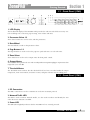
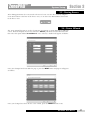
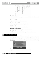
1
1260/1261
User Manual
IMPORTANT SAFETY INSTRUCTIONS
WARNING FOR YOUR PROTECTION
READ THESE INSTRUCTIONS:
KEEP THESE INSTRUCTIONS
HEED ALL WARNINGS
The symbols shown above are internationally accepted
symbols that warn of potential hazards with electrical
products. The lightning flash with arrowpoint in an equilateral triangle means that there are dangerous voltages
present within the unit. The exclamation point in an equilateral triangle indicates that it is necessary for the user to
refer to the owner’s manual.
These symbols warn that there are no user serviceable
parts inside the unit. Do not open the unit. Do not
attempt to service the unit yourself. Refer all servicing to
qualified personnel. Opening the chassis for any reason
will void the manufacturer’s warranty. Do not get the unit
wet. If liquid is spilled on the unit, shut it off immediately
and take it to a dealer for service. Disconnect the unit
during storms to prevent damage.
FOLLOW ALL INSTRUCTIONS
DO NOT USE THIS APPARATUS NEAR WATER
CLEAN ONLY WITH A DRY CLOTH.
DO NOT BLOCK ANY OF THE VENTILATION OPENINGS. INSTALL IN ACCORDANCE WITH
THE MANUFACTURER’S INSTRUCTIONS.
DO NOT INSTALL NEAR ANY HEAT SOURCES SUCH AS RADIATORS, HEAT REGISTERS,
STOVES, OR OTHER APPARATUS (INCLUDING AMPLIFIERS) THAT PRODUCE HEAT.
ONLY USE ATTACHMENTS/ACCESSORIES SPECIFIED BY THE MANUFACTURER.
UNPLUG THIS APPARATUS DURING LIGHTNING STORMS OR WHEN UNUSED FOR LONG
PERIODS OF TIME.
Do not defeat the safety purpose of the polarized or grounding-type plug. A polarized plug has two blades with one wider than the other. A grounding type plug has
two blades and a third grounding prong. The wide blade or third prong are provided for your safety. If the provided plug does not fit your outlet, consult an electrician for replacement of the obsolete outlet.
Protect the power cord from being walked on or pinched particularly at plugs, convenience receptacles, and the point where they exit from the apparatus.
SAFETY INSTRUCTIONS
NOTICE FOR CUSTOMERS IF YOUR UNIT IS EQUIPPED
WITH A POWER CORD.
Use only with the cart stand, tripod bracket, or table specified by the manufacture,
or sold with the apparatus. When a cart is used, use caution when moving the
cart/apparatus combination to avoid injury from tip-over.
WA R N I N G : T H I S A P P L I A N C E M U S T B E E A RT H E D.
CONNECT ONLY TO A MAINS SOCKET OUTLET WITH
PROTECTIVE EARTHING CONNECTION.
The cores in the mains lead are coloured in accordance with
the following code:
GREEN and YELLOW - Earth
BLUE - Neutral
BROWN - Live
As colours of the cores in the mains lead of this appliance may
not correspond with the coloured markings identifying the terminals in your plug, proceed as follows:
• The core which is coloured green and yellow must be connected to the terminal in the plug marked with the letter E, or
with the earth symbol, or coloured green, or green and yellow.
• The core which is coloured blue must be connected to the
terminal marked N or coloured black.
• The core which is coloured brown must be connected to the
terminal marked L or coloured red.
This equipment may require the use of a different line cord,
attachment plug, or both, depending on the available power
source at installation. If the attachment plug needs to be
changed, refer servicing to qualified service personnel who
should refer to the table below. The green/yellow wire shall be
connected directly to the units chassis.
Refer all servicing to to qualified service personnel. Servicing is required when
the apparatus has been damaged in any way, such as power-supply cord or plug is
damaged, liquid has been spilled or objects have fallen into the apparatus, the apparatus has been exposed to rain or moisture, does not operate normally, or has been
dropped.
POWER ON/OFF SWITCH: For products provided with a power switch, the power
switch DOES NOT break the connection from the mains.
MAINS DISCONNECT: The plug shall remain readily operable. For rack-mount or
installation where plug is not accessible, an all-pole mains switch with a contact
separation of at least 3 mm in each pole shall be incorporated into the electrical
installation of the rack or building.
FOR UNITS EQUIPPED WITH EXTERNALLY ACCESSIBLE FUSE RECEPTACLE: Replace fuse
with same type and rating only.
MULTIPLE-INPUT VOLTAGE: This equipment may require the use of a different line
cord, attachment plug, or both, depending on the available power source at installation. Connect this equipment only to the power source indicated on the equipment
rear panel. To reduce the risk of fire or electric shock, refer servicing to qualified
service personnel or equivalent.
This Equipment is intended for rack mount use only.
WARNING: If the ground is defeated, certain fault conditions in
the unit or in the system to which it is connected can result in
full line voltage between chassis and earth ground. Severe injury
or death can then result if the chassis and earth ground are
touched simultaneously.
IMPORTANT SAFETY INSTRUCTIONS
U.K. MAINS PLUG WARNING
ELECTROMAGNETIC
COMPATIBILITY
This unit conforms to the Pro d u c t
Specifications noted on the Declaration
of Conformity. Operation is subject to
the following two conditions:
• this device may not cause harmful
interference, and
• this device must accept any interference received, including interference
that may cause undesired operation.
Operation of this unit within significant
electromagnetic fields should be avoided.
• use only shielded interconnecting
cables.
A molded mains plug that has been cut off from the cord is unsafe.
Discard the mains plug at a suitable disposal facility. NEVER UNDER
ANY CIRCUMSTANCES SHOULD YOU INSERT A DAMAGED OR CUT
MAINS PLUG INTO A 13 AMP POWER SOCKET. Do not use the
mains plug without the fuse cover in place. Replacement fuse covers
can be obtained from your local retailer. Replacement fuses are 13
amps and MUST be ASTA approved to BS1362.
DECLARATION OF
CONFORMITY
Manufacturer’s Name:
Manufacturer’s Address:
dbx Professional Products
8760 S. Sandy Parkway
Sandy, Utah 84070, USA
declares that the product:
Product name:
dbx 1260 and dbx 1261
Note: Product name may be suffixed by the letters-EU.
Product option:
None
conforms to the following Product Specifications:
Safety:
IEC 60065 (1998)
EMC:
EN 55013 (1990)
EN 55020 (1991)
Supplementary Information:
The product herewith complies with the requirements of the
Low Voltage Directive 73/23/EEC and the EMC Directive
89/336/EEC as amended by Directive 93/68/EEC.
Vice-President of Engineering – Pro
8760 S. Sandy Parkway
Sandy, Utah 84070, USA
Date:August 23, 2004
European Contact: Your local dbx Sales and Service Office or
Harman Music Group
8760 South Sandy Parkway
Sandy, Utah 84070, USA
Ph: (801) 566-8800
Fax: (801) 568-7583
ZonePRO™
Introduction
Introduction
4.12 Output Dynamics .........................................32
0.1 ZonePro Features .............................................ii
4.13 Delay .............................................................33
4.14 Output Polarity .............................................33
0.2 Service Contact Info ........................................iii
0.3 Warranty...........................................................iv
Section 1 - Getting Started
1.1 Rear Panel Connections ...................................2
1.2 (1260)Front Panel .............................................3
Section 5- Application Guide
5.1 Restaurant Install ............................................36
5.2 Health Club.....................................................38
5.3 Night Club.......................................................40
1.3 (1261)Front Panel .............................................3
1.4 ZonePRO Designer GUI ..................................4
Section 6- Application Notes
1.5 Software Installation.........................................4
6.1 Using the Input Link Bus...............................44
Section 2 - Software Overview
6.2 Using the ZC as a Scene Selector .................44
6.3 Using the ZC-Fire ...........................................44
2.1 ZonePRO Philosophy.......................................6
2.2 Views.................................................................6
2.3 Venue View Functions .....................................6
2.4 Unit View Functions.........................................8
2.5 Module View Functions .................................10
Section 3 - Software Operation
3.1 Overview.........................................................12
3.2 Connecting to the Device ..............................12
3.3 Configuration Wizard .....................................12
3.4 Parameter Editing ...........................................16
3.5 Storing Scenes.................................................17
3.6 Scene Wizard ..................................................17
3.7 Schedule Wizard.............................................18
3.8 File Save..........................................................18
3.9 Hardware Navigation .....................................18
Section 4 - Detailed Parameters
4.1 Input................................................................20
4.2 Parametric EQ.................................................20
4.3 Advanced Feedback Suppression (AFS) .......21
4.4 Automatic Gain Control (AGC) .....................23
4.5 Noise Gate ......................................................24
4.6 Compressor .....................................................25
4.7 De-Esser ..........................................................27
4.8 Notch Filters....................................................28
4.9 Router/Mixer ...................................................28
4.10 Auto Warmth.................................................30
4.11 Band Pass Filter/Crossover .........................31
Table of Contents
ZonePRO™ User Manual
6.4 Using the Locate Function .............................45
6.5 Using the Address Network Wizard..............45
Appendix
A.1 Factory Reset/Flash Update...........................50
A.2 Specifications..................................................51
A.3 Block Diagram ...............................................52
A.4 Link I/O..........................................................53
A.5 Zone Controller Wiring and Install...............54
A.6 Network Overview ........................................57
A.7 Copyright........................................................64
ZonePRO™
INTRODUCTION
INTRO
CUSTOMER SERVICE INFO
Defining the
ZonePRO
WARRANTY INFO
Introduction
INTRODUCTION
ZonePRO™
Congratulations on your purchase of the dbx® ZonePRO 1260 and/or 1261! The ZonePRO products are based on the same unparalleled design philosophy that made the DriveRack family
famous. This philosophy, “To provide everything you need between the sources and the amplifiers,” creates a full featured processor capable of almost any BGM or commercial audio application.
This manual will be your guide to understanding the full functionality of the powerful ZonePRO
units By combining the different components, the configuration possibilities are limitless. After
you have become familiar with the unit, we encourage you to experiment and find the most
effective and efficient way to run your system by utilizing the powerful processing of the
ZonePRO 1260 and 1261.
0.1 - ZonePro Features
ZonePRO 1260/1261 features:
• Individual Zone Routing or Mixing
• Advanced Feedback Suppression (AFS™)
• AutoWarmth®
• Auto Gain Control
• Compression
• Limiting
• Noise Gating
• Notch Filtering
• Bandpass and Crossover Filters
• Parametric EQ
• Security Lockout
• Wall Panel Control
• RS-232 and Ethernet Control
• IEC, UL, and CSA Certified
ii
ZonePRO™ User Manual
ZonePRO™
Introduction
In addition to the processing available, the ZonePRO units provide intuitive wall-panel control
from the dbx Zone Controller (ZC) series. The ZC-1 and ZC-6 offer remote programmable
Volume control to any installation using the ZonePRO units. The ZC-2 provides programmable
Volume and Mute control. The ZC-3 and ZC-4 allow Source selection, Scene selection or Page
steering. ZC-FIRE provides an interface for fire safety systems. The ZC-7 remote offers page
steering from a programmable push button interface. The ZC-8 provides a single panel with
both push button volume control and source selection. The ZC-9 provides source selection. Up
to 12 Zone Controllers can be used with a single ZonePRO, and can either be wired in series
or parallel. The ZC-BOB was created to accommodate “home-run” or parallel wiring to the unit.
With a maximum length of 1,000 ft., the Zone Controllers offer a simple way to create a simple
yet elegant solution to many installation applications.
ZC-BOB
ZC-1
ZC-2
ZC-3
ZC-Fire
ZC-6
ZC-7
ZC-8
ZC-4
ZC-9
0.2 - Service Contact Info
If you require technical support, contact dbx Customer Service. Be prepared to accurately
describe the problem. Know the serial number of your unit - this is printed on a sticker attached
to the top panel. If you have not already taken the time to fill out your warranty registration
card and send it in, please do so now.
Before you return a product to the factory for service, we recommend you refer to the manual. Make sure you have correctly followed installation steps and operation procedures. If you
are still unable to solve a problem, contact our Customer Service Department at (801) 568-7660
for consultation. If you need to return a product to the factory for service, you MUST contact
Customer Service to obtain a Return Authorization Number.
No returned products will be accepted at the factory without a Return Authorization Number.
ZonePRO™ User Manual
iii
Introduction
ZonePRO™
Please refer to the Warranty information on the following page, which extends to the first enduser. After expiration of the warranty, a reasonable charge will be made for parts, labor, and
packing if you choose to use the factory service facility. In all cases, you are responsible for
transportation charges to the factory. dbx will pay return shipping if the unit is still under warranty.
Use the original packing material if it is available. Mark the package with the name of the shipper and with these words in red: DELICATE INSTRUMENT, FRAGILE! Insure the package properly. Ship prepaid, not collect. Do not ship parcel post.
0.3 - Warranty
This warranty is valid only for the original purchaser and only in the United States.
1. The warranty registration card that accompanies this product must be mailed within 30 days
after purchase date to validate this warranty. Proof-of-purchase is considered to be the burden of the consumer.
2. dbx warrants this product, when bought and used solely within the U.S., to be free from
defects in materials and workmanship under normal use and service.
3. dbx liability under this warranty is limited to repairing or, at our discretion, replacing defective materials that show evidence of defect, provided the product is returned to dbx WITH
RETURN AUTHORIZATION from the factory, where all parts and labor will be covered up to
a period of two years. A Return Authorization number must be obtained from dbx by telephone. The company shall not be liable for any consequential damage as a result of the product's use in any circuit or assembly.
4. dbx reserves the right to make changes in design or make additions to or improvements upon
this product without incurring any obligation to install the same additions or improvements
on products previously manufactured.
5. The foregoing is in lieu of all other warranties, expressed or implied, and dbx neither
assumes nor authorizes any person to assume on its behalf any obligation or liability in connection with the sale of this product. In no event shall dbx or its dealers be liable for special
or consequential damages or from any delay in the performance of this warranty due to causes beyond their control.
iv
ZonePRO™ User Manual
ZonePRO™
Section 1
Getting Started
Section 1
Getting Started
ZonePRO™
1.1 - Rear Panel (1260 and 1261)
1. IEC Power Cord Receptacle
The ZonePRO 1260/1261 comes with a power supply that will accept voltages ranging from
100V-240V at frequencies from 50Hz-60Hz. An IEC cord is included.
2. S/PDIF Connection
This RCA connection is used to connect up to two digital input channels in the 1260/1261.
3. PC Connection (DB-9)
This DB-9 connection is used to communicate to the PC GUI and uses RS-232 protocol. This
connection requires a Null modem cable and one is included with the ZonePRO unit.
4. Ethernet Connection (RJ-45)
This RJ-45 connection is used to control the unit via Ethernet.
5. Zone Control Inputs 1-12 (RJ-45)
This input connection is used to send information and power to the ZC wall controllers.
6. Outputs Channels 1-6 (Euroblock)
The output section of the ZonePRO offers six electronically balanced Euroblock connectors.
7. Input Link Buss (RJ-45)
The ZonePRO offers an input buss that duplicates the first six inputs from one unit to the next
for applications requiring more than six output zones.
8. Input Source Channels 1-8 (RCA)
The input section of the ZonePRO offers eight mono-summing unbalanced RCA connectors.
9. Line/Mic Selector
This switch is used to select either the line or microphone input.
10. Signal/Clip LED
This LED is used to indicate microphone signal input or clip.
11. Mic/Line Inputs 1-2 (Euroblock)
The input section of the ZonePRO provides two Euroblock connectors for mic/line inputs.
12. Mic Gain Control
This knob is used to set the input gain for the microphone input.
2
ZonePRO™ User Manual
ZonePRO™
Getting Started
Section 1
1.2 - Front Panel (1260)
1. LCD Display
The backlit LCD display of the ZonePRO 1260 provides the end-user with all the necessary controls including source selection, page steering, zone volume and mute.
2. Parameter Select 1-3
These three buttons are used to select and edit parameters.
3. Data Wheel
The Data Wheel is used to edit parameter values.
4. Page Buttons 1-2
The Page buttons are used to select the page mic path and steer it to selected zones.
5. Zone Select
These buttons are used to select output zones for front panel control.
6. Output Meters
The ZonePRO 1260 provides the user with six independent six-segment Lightpipe output meters that
range from -30 to +20 dBu.
7.Threshold Meters
The threshold meters indicate that the threshold level has been exceeded within the output
Compressor, Auto Gain Control, or Limiter sections, and gain reduction may be taking place.
1.3 - Front Panel (1261)
1. PC Connection
This DB-9 connection is used to communicate to the PC via RS-232 protocol.
2. Network Traffic LED
This LED is used to indicate Network Traffic; it is also used to indicate and identify the unit
when the Locate function is enabled.
3. Power LED
This LED (when lighted), indicates that the ZonePRO 1261 is currently powered.
ZonePRO™ User Manual
3
Section 1
Getting Started
ZonePRO™
1. 4 - ZonePRO Designer GUI
The ZonePro Designer Graphic User Interface (GUI) provides all the control functions necessary to configure and program the ZonePro products. The GUI provides network tools for
configuring your control network as well as multiple “Wizard” functions for configuring the
system routing, implementing end-user control surfaces, programming parameters, and even
creating automatic system changes. Understanding the ZonePro Designer software is the key
to getting full functionality from ZonePro products.
1.5 - Software Installation
Minimum System Requirements for ZonePRO Designer are:
1 GHz or faster processor
Windows 2000 or XP
256 MB RAM or (512 MB Recommended)
Recommended screen resolution: 1024 x 768 pixels or higher
Installation
• Install the ZonePRO GUI software from either the dbx website at www.dbxpro.com or from
the included CD ROM onto your computer.
• Once the software setup is downloaded, double click on the file named: ZonePRO setup.
• The application will proceed to prompt you for the installation location.
• Once the software installation has been completed, it is recommended that you restart your
computer.
Note
You must disable virus protection software during the installation of
ZonePRO Designer.
4
ZonePRO™ User Manual
ZonePRO™
Section 2
SOFTWARE
OVERVIEW
Section 2
Software Overview
ZonePRO™
For your convenience, all the configuration and editing features of the ZonePRO™ 1260 and
1261 are performed via the included ZonePRO Designer GUI. This section has been created to
act as a tutorial for performing various editing aspects of the unit.
2. 1 - ZonePRO Philosophy
The philosophy of the ZonePRO Designer and the files that it creates, are built around the concept of a configuration, a scene and a device file; all of which are found in the Unit View
(Please see below).
Configuration
The configuration includes all of the processing blocks, the I/O configuration, and the zone
controllers. The configuration is set up by going through the Configuration Wizard. The
ZonePRO device can only have one configuration, so all configuration editing must be completed before you can store any scenes. For more information on the configuration see
Configuration Wizard in section 3.3.
Scenes
A scene consists of the parameters for all the modules and the assignment of zone controllers
to a zone. The ZonePRO products allow switching of scenes from the Real Time Clock, or from
a ZC zone controller. Up to 50 scenes can be stored in the ZonePRO unit. Scenes can be stored
by clicking on the Store Scene button in the Unit view. For more information on scenes, see
section 3.5.
Device
The configuration, scenes, and schedule information can all be stored off to a device file or .zpd
(ZonePRO device). Storing a device file to the computer and then recalling it into another
ZonePRO unit allows for exact duplication of a system in a single file download. The device
file can be stored by selecting File Save in the Unit view.
2. 2 - Views
There are three different views within the ZonePRO Designer GUI; Venue view, Program
screen, and Module view. Venue view Venue View gives you a global view of the network
including all your units if you are using Ethernet control. Double clicking on a unit icon in the
Venue view take you to the Unit view. Unit View (sometimes called program screen) provides you with a graphic representation of the configuration of the individual ZonePRO unit,
including all the processing modules and their positions in the signal path. The program screen
also offers access to meters, scene storing and loading, the Wizard functions, and file storing.
Double clicking on the processing modules take you to the Module view. Module view (also
called edit screen) provides access to the processing parameters. Editing of parameters is done
in Module view.
2. 3 - Venue View Functions
2.3.1 Device Menu
The ZonePRO Designer GUI provides a mechanism for creating scenes and device files while
not physically connected to a ZonePRO unit. To work off-line, open the GUI, select the
Device Menu from the menu bar then select Add. At this point you will be prompted to
choose a 640, 641, 1260 or 1261. Once the unit has been inserted into GUI you can proceed
to configure, edit, create scenes, and save ZonePRO device files. If you highlight the
ZonePRO unit and select Edit, you will be taken to the Unit view so that you can edit the
6
ZonePRO™ User Manual
ZonePRO™
Software Overview
Section 2
unit; double clicking on the unit also takes you to the Unit view. When off - l i n e , You can delete
the unit by selecting Delete f rom the Device Menu. Selecting Properties f rom the Device
menu allows you to view and edit some of the device properties like the device's name, its
MAC address, Its Node address, and its peak output level. From the Properties selection, you
can also see the firm w a re or OS (Operating System) version that the device has loaded
2.3.2 Network Menu
The Network Menu provides access to network parameters. If the computer cannot connect to
the ZonePro device you can select Properties from the Network Menu and check the COM
port assignment to make sure that you are connecting to the correct COM port. The Network
Menu also provides an Address Tool that can be used to discover other devices on the network
and resolve any address conflicts that may arise between units.
Note: Nodes
Any device that is on the network is considered a node and must be given a node address; this
is just usually a simple one or two digit number. Once you place the first device on the network the GUI will assist you as you add further devices by adding 1 to the previous node
address as you add devices. For example, if the first device on the network is node address 1,
the second will be 2, and the third 3, unless you specifically change the node address with the
Network Address Tool. If the computer cannot connect to the ZonePRO device, check the COM
port assignment under Network Properties in the Venue View, and make sure that you are connecting to the correct COM port.
Note: Setting up a basic Network
The enclosed crossover Ethernet cable is used to connect a computer directly to a ZonePRO
1260/1261 without a hub or a switch. If you are using a hub or a switch, you must provide
your own cabling. Since this cable is a crossover cable, it can not be used to wire Zone
Controllers or link to multiple ZonePRO units together using the Input Link Bus.
The factory default IP settings for the ZonePRO are as follows:
IP Address:
Subnet Mask:
Default Gateway:
169.254.2.2
255.255.0.0
0.0.0.0
These default settings are used for a simplified configuration when using Microsoft Window's
Automatic IP assignment. When Windows is configured to automatically obtain its IP settings
it will fall back to a network configuration that is compatible with the ZonePRO 1260 / 1261 if
the computer is on a network without a DHCP/BOOTP server. Using the enclosed crossover
cable is an example of such a network and is the recommended method of configuring a new
unit. Please keep in mind that it takes MS Windows 1-2 minutes after the cable is attached and
the ZonePRO is powered on for it to have its network settings compatible with the ZonePRO.
Because of this, do not start the ZonePRO Designer software for about 2 minutes after the cables
have been attached. For more information on how to properly configure the network setting
please refer to the appendix.
ZonePRO™ User Manual
7
Section 2
Software Overview
ZonePRO™
2. 4 - Unit View Functions
The Unit View provides access to the signal routing configuration, Zone Controller assignment,
and processing parameters.
2.4.1 File Menu
The File Menu selection allows saving of the existing ZonePRO device file (.zpd) as well as
recalling of other files. The device file provides a way to store off the entire ZonePRO unit to
a computer, which includes the configuration, scenes, and schedule information. To save a
ZonePRO device file, select File then Save from the Menu bar. Recalling a saved file can be
done by selecting Open from the File Menu. Once all of your changes have been made, simply close the file with the Close selection.
2.4.2 Edit Menu
To edit a processing module, double click on that module. Adjust the module to taste; make
sure that the module is engaged. This is usually indicated by the module ON button in the
upper left corner of the parameter section. Although process editing is done in real-time, the
changes can either be discarded or accepted by selecting the OK or CANCEL button.
Parameters can be copied and pasted between like modules in the ZonePRO GUI. From the
program screen either right click on the module and select Copy, or select Edit and Copy from
the Menu Bar to Copy parameters. To paste, either right click and select Paste, or click on Edit
Paste from the Menu bar. Selecting Time in the Edit Menu allows editing of the date and time
in the ZonePRO device's real time clock
2.4.3 Scenes Menu
Scenes include parameter data and zone controller assignment. Multiple scenes can be saved
and recalled by either clicking on the Scene tab of the Menu bar and selecting Store or Recall
Scene, or by using the Store Scene and Recall Scene buttons at the bottom of the Unit view window.
8
ZonePRO™ User Manual
ZonePRO™
Software Overview
Section 2
2.4.4 Wizard Menu
The Wizard Menu provides setup functions for the unit configuration, scene changes that might
involve routing or ZC assignment changes, and automated scene changes via the real time clock
schedule. Configuration of the ZonePRO device is done from the Configuration Wizard and
allows setup of the inputs and outputs along with selection of their processing modules, zone
controller setup, signal routing, and front panel setup. For a detailed operation description see
"The Wizard" section 3.3. The image on the following page shows the first page of the
Configuration Wizard page.
The Scene Wizard allows routing and ZC assignment changes for different scenes. Scheduling
Scene Changes is done using the Schedule Wizard. Selecting the Schedule Wizard from the
Wizard Menu reveals the image below where scenes can be recalled at various times throughout the day or week.
2.4.5 Help Menu
The Help Menu provides for some special functions like retrieving Hardware Info such as
Checksum and Fire Safety status. There is a Locate function similar to the Locate function
found under the Device Menu in the Venue view. A special provision for the 641 and 1261 is
found in the Help menu under 641/1261 Operations that can be used to do hard or soft resets
on those units if the need arises. Finally the GUI software version is found under About in the
Help menu.
2.4.6 Meters Button
The Meters Button, found at the bottom of the Unit view can be used to turn the meters off.
Turning the meters off will help speed the communication and processing of slower computer
systems. The ZonePRO Designer GUI defaults with the meters turned on.
ZonePRO™ User Manual
9
Section 2
Software Overview
ZonePRO™
2. 5 - Module View Functions
Double clicking on a processing module provides access to those parameters.
All modules except for the input Gain module and the output Polarity have ON/OFF buttons
allowing the processing of that module to be bypassed. Any changes made to the processing
happen in real time as long as the ON/OFF button is turned on (indicated by the button turning red). These changes can be accepted or discarded upon exiting the module by selecting
either the OK or CANCEL button at the bottom of the module view.
10
ZonePRO™ User Manual
ZonePRO™
Section 3
Setup
SOFTWARE
OPERATION
Section 3
Software Operation
ZonePRO™
3.1 - Overview
The Software operation section of the manual will provide in-depth step by step instructions
for setting up a ZonePro 1260 or 1261 and any Zone Controllers that may be used with it.
The following subsections will provide you with detailed information regarding the various
set up functions. Typical procedure of a ZonePro 1260 is as follows:
Step 1, Connect to the Device - Use either RS-232 or Ethernet to connect to the ZonePro unit.
Step 2, Configuration Wizard - Once you have connected to the device you can begin to configure the signal routing, DSP functions, and wall panel controllers using the Configuration
Wizard.
Step 3, Parameter Editing - Double clicking on the various modules allows editing of parameters to adjust settings for individual installations or scenes.
Step 4, Scene Storing - Whether using a single scene or many, storing the scene is important to
make sure that all parameter changes are saved. If just one scene is desired you can save it
as the Default scene.
Step 5, Scene Wizard - If multiple scenes are desired with routing or zone controller assignment changes, use the Scene Wizard to make those changes. Repeat Steps 3 and 4.
Step 6, Schedule Wizard - If multiple scenes are to be loaded using the Schedule function, set
up the Schedule using the Schedule Wizard for each scene change. Make sure the clock is
correct by clicking on Edit then Time from the Menu Bar.
Step 7, File Save - It is recommended that you save off a copy of your ZonePRO device file
using the File Save on the Menu bar. This file is a back-up and might come in handy for
future installations.
3.2 - Connecting to the Device
If you are connecting to a device with an RS-232 connection the connection should be established fairly quickly. If you have difficulty connecting to the ZonePRO unit you can use the
Network Wizard to select the proper COM port.
If you are using your Ethernet port on your computer this may take up to two minutes as
Windows tries to first establish an Ethernet connection. If after two minutes your computer
cannot connect to the ZonePro device you may want to select NETWORK/GO OFFLINE wait
ten seconds then select NETWORK/GO ONLINE from the Venue view.
If you are setting up a larger network with multiple devices, please see Appendix for more
information.
3.3 - Configuration Wizard
The Wizard function is used to configure the ZonePRO signal routing, processing modules,
Zone Controllers and Front Panel. It provides a menu based decision tree to speed setup. This
sub-section will walk you through each page of the Wizard function.
From the Program Screen view of the setup, select the Wizard pull down from the
menu bar and then select the option labeled Configuration Wizard. Once selected, a window will appear as follows:
12
ZonePRO™ User Manual
ZonePRO™
Software Operation
Section 3
3.3.1 Source Configuration
This page is the Input Setup Page, and allows naming of inputs, input configuration (mono or
stereo), and selection of the two mic/line DSP modules. Once you have named your inputs
and selected insert modules, click on the Next Page button and the display will appear as follows:
3.3.2 Zone Configuration
This page is the Output Setup Page and allows naming of the outputs, zone configuration,
and selection of the Dynamics DSP module. The outputs can be configured as mono, or
stereo either with or without a subwoofer. You can also select whether you want a mixer or
routing module as part of your zone. Once you have performed all of your output setup
modifications, click on the Next Page button and the display will appear as follows:
ZonePRO™ User Manual
13
Section 3
Software Operation
ZonePRO™
3.3.3 ZC Panel Configuration
The ZC Panel Configuration Page allows setup of wall-mounted Zone Controllers to be used
with the ZonePRO unit.
ID #s - The ID numbers on the left side of the window correspond to the identification number set using the DIP switches on the individual zone controllers. To select ID#2 for example,
simply flip the 2 switch into the on position. ID 1-6 are connected to one of the ZC inputs on
the rear panel and ID 7-12 are connected to the other input. For ID 7-12 add 6 to the ID #
selected on the back of the ZC. For example, to get an ID# of 10, connect to ZC Input 7-12
and set the ID# to 4.
Types - The zone controllers can be named to eliminate confusion in later menus.
Since several zone controllers have multiple functions examples of each function will be shown:
Scenes - To change scenes a ZC-3 or ZC-4 must be used in the ID #1 position. This zone controller must have the scene check box checked. Select the desired scenes from the list of scenes
on the right hand side of the window and associate it with the selector position A, B, C, D on
a ZC-3 or switch position 1-16 on a ZC-4 (see ZC-4 switch positions within the Appendix).
Fire - The ZC-FIRE is a special case of scene selection. A ZC-FIRE can only be assigned to ID
#2. Select whether the ZC-FIRE should be activated when taken high or low. Select to either
Mute all outputs, or select the desired scene to be loaded.
Name - The zone controller can be named to eliminate confusion in later menus.
Page- If Page steering is desired, a ZC-3, ZC-4 or ZC-7 must be used. To select Page steering,
select the Page box on the ZC-3 and 4, the ZC-7 will come up with the Page box automatically
selected Then select the Paging source from Mic 1, Mic 2, S1 or S2.
Edit- Setting parameters for the Zone Controllers is done by clicking on the Edit button.
Edit - Volume - A ZC-1, ZC-2, ZC-6, or ZC-8 can be used to adjust volume. Select the
desired ZC type, and make sure it has the correct ID number. Set the maximum and minimum values for this zone controller. As a default, all volume zone controllers can provide
up to +20dB gain boost and can cut to -Inf to mute.
14
ZonePRO™ User Manual
ZonePRO™
Software Operation
Section 3
Edit - Source Selection - A ZC-3, ZC-4, ZC-8, or ZC-9 can be used to provide
source selection. Select the desired ZC type and make sure it has the correct
ID number. For a ZC-3, ZC-8, or ZC-9 for each switch position, select the corresponding source. For a ZC-4, select the switch position 0-15 and choose the
corresponding input source (see ZC-4 switch positions within the Appendix).
Edit - Page Routing - For a ZC-3, only four zones or groups of zones can be
switched between. A ZC-4 can switch between 16 zones or groups of zones.
Like a ZC-3, the ZC-7 only has four positions, so it will only support up to four
zones or groups of zones, but it does have momentary switches that can be
used in a push-to-call fashion, where each switch must be pushed and held to
route the page to that zone or group of zones. Once you have performed all
your zone controller configurations, click NEXT to move to the Routing
Configuration.
3.3.4 Source Association
The Source Association page allows selection of the main Source, the Priority override source,
the Page source, and the output level for each of the output zones. The Source ZC page
appears as follows:
3.3.5 Routing and Zone ZC Association
The Routing configuration Page allows selection of the main Source, the Priority override
source, the Page source, and the output level for each of the output zones. If Zone
Controllers are used for either source selection or level control, these should be selected in
the Source or Level pulldown menu. If zone controllers are being used for Page Steering
select None in the Page menu for those outputs unless a microphone is always paging to that
zone in addition to the page steering.
ZonePRO™ User Manual
15
Section 3
Software Operation
ZonePRO™
3.3.6 Front Panel Configuration
The Front Panel Setup Page allows selection of which controls will be available to the end-user
of the ZonePRO unit. If Zone Controllers are being used for page steering, source, or volume
c o n t rol of an output zone these parameters will not be available from the front panel.
Once all the Wizard pages have been completed the configuration is ready to be loaded, this
is accomplished by selecting finish. You will now be returned to the normal editing mode of
the ZonePRO GUI.
3.4 - Parameter Editing
All parameters can be edited by double clicking on the module. All the individual parameters are discussed, and can be seen in Section 4.
16
ZonePRO™ User Manual
ZonePRO™
System Setup
Section 3
3.5 - Storing Scenes
After editing parameters the scene needs to be stored. You can store the scene by using the
Scene Store button at the base of the device view, or use the Scene Wizard Menu also found
in the device view.
3.6 - Scene Wizard
The Scene Wizard function is used to change ZC associations, or Zone Routing for different
scenes. From the Program Screen view Select the Wizard pull down from the menu bar and
then select the option labeled Scene Wizard. Once selected, a window will appear as follows:
Once your changes have been made for page 1, press the NEXT button and page 2 will appear
as follows:
Once your changes have been for the scene wizard, press the FINISH button to exit.
ZonePRO™ User Manual
17
Section 3
System Setup
ZonePRO™
3.7 - Schedule Wizard
The Schedule Wizard provides for pre-determined scene changes corresponding to the time of
day and/or day of week. For example installations such as restaurants often require volume
increases during peak hours of operation. This sub-section will walk you through setting up
the Schedule Wizard.
From the Unit view of the setup, Select the Wizard pull down from the menu bar and
then select the option labeled Schedule Wizard. Once selected, a window will appear as
follows:
At this point you can create a schedule for each day of the week, by recalling scenes at any
time with up to 1 minute resolution. Up to 24 scenes can be recalled per day. Once all
changes have been made, select Ok or Cancel and the window will be closed.
3.8 - File Save
After editing and storing the scene or scenes you can store this file to your computer by
selecting File Save from the Device View menu.
3.9 - Hardware Navigation
Many functions of the ZonePRO 1260 can be accessed and performed from the front panel of
the unit. The following information will cover several areas of operation of the 1260.
Changes to the output zones can be made by pressing the buttons associated with them. Once
and output button is pressed the available parameters are located on the front panel display.
To edit any of them simply press button 1, 2, or 3 and edit that parameter. The page routing
can also be edited in a similar fashion; press the button associated with that page microphone
and select the desired routing.
18
ZonePRO™ User Manual
ZonePRO™
Section 4
Detailed Parameters
DETAILED
PARAMETERS
Section 4
Detailed Parameters
ZonePRO™
The following section will provide you with a module block representation for each effect, as
well as descriptions and explanations of all parameters within the ZonePRO.
4.1 - Input
The signal routing begins at the INPUT block of the ZonePRO™.
Gain Level -Inf to 20dB
Adjusts the input level.
HP Frequency Off, 14.96Hz to 118.85Hz (Mic Inputs and RCA S1-S2)
Adjusts the input High Pass cutoff frequency on the mic/line inputs.
4.2 - Parametric EQ
The ZonePRO units offer both Pre and Post-crossover parametric sections on each input, and
may be configured as a single or linkable 2-band or 4-Band PEQ (Mic inputs and RCA S1 and
S2).
EQ On/Off
Turns the PEQ on and off.
Type Low Shelf, HighShelf, Low/High Shelf and Bell
The Type selector allows you to select either a Low, High, Low/High shelf or Bell EQ curve.
20
ZonePRO™ User Manual
ZonePRO™
Detailed Parameters
Section 4
Flat /Restore
These buttons either flatten (Flat) or restore (Restore) all bands to their original settings.
Band (1-4) Frequency 20Hz to 20kHz (Low Shelf)
Selects the frequency of the EQ.
Q (1-4) 0.105 to 16.0
Selects the Q or the Bell parametric EQ.
Slope (Type: High and/or Low Shelf Selected) 3-12dB/Octave
Sets the slope of the High and/or low shelf parametric EQ.
Level (1-4) -12 to 12 dB
Sets the amount of boost or cut of the selected parametric EQ.
4.3 - AFS (Insert Module)
The ZonePRO™ offers the exclusive patent pending AFS (Advanced Feedback Suppression)
feedback elimination module. Feedback is caused when a microphonic signal such as a guitar
pickup or microphone is reproduced by an amplification and is repeatedly picked up in phase.
The AFS module of the ZonePRO™ allows the user to optimize the elimination of feedback.
With the AFS algorithm active the ZonePRO removes only the feedback frequencies without
affecting the remaining audio spectrum.
AFS On/Off
Turns the AFS module on and off. If AFS is Off, the filters are bypassed, and the algorithm is
halted (the filters are not updated). If AFS is On, the filters are active, and the they are updated according to the current selected mode (Fixed or Live).
Clear Live and ClearAll
These buttons (when selected) clear the filters. If Clear Live is selected, only the live filters are
reset. If Clear All is selected, then all of the filters are reset.
ZonePRO™ User Manual
21
Section 4
Detailed Parameters
ZonePRO™
Mode - Live or Fixed
When the mode is Fixed, the algorithm updates only the fixed filters. When the mode is Live,
the algorithm updates only the live filters. In FIXED mode, the filters are stored with the program at that frequency until cleared by the user. Fixed mode is used during setup to set filters
at frequencies that are most likely to feedback. In LIVE mode, the live filters automatically
detect and remove feedback during the performance. When all of the live filters have been
used, they begin to round robin. Essentially this means that the first filter set is moved where
a new feedback is detected and notched out. This mode is useful because feedback frequencies may change as the microphone is moved, and/or as the characteristics of the venue change.
Note- Only the fixed filter settings will be stored with the program.
Type - Speech, Low Music, Medium Music and High Music
Type allows the AFS algorithm to be customized for the application. The Values correspond
to different Q and sensitivity settings. These types pertain to the Q, sensitivity, and algorithm
type. Values are; Speech (Bandwidth = 1/5 octave and Q=7.25) Music Low (Bandwidth = 1/10
octave and Q=14.5) Music Medium (Bandwidth = 1/20 octave and Q=29) Music High
(Bandwidth = 1/80 octave and Q=116). Note: To guarantee that feedback is suppressed at
lower frequencies, the AFS may place wider notch filters at these lower frequencies (below
700 Hz).
Total Number of Filters 1-12
This parameter selects the number of filters being used
Number Fixed - 0-12
This parameter sets the number of Fixed AFS filters. This also sets the number of Live filters as
the Total number of filters - number of Fixed Filters = number of Live Filters.
Live Filter Lift (On/Off)
This parameter turns the Live Filter Lift on and off.
Lift After - 5 sec to 60 min
This parameter allows the user to setup the box so that the Live filters will automatically be
removed after a set time (as indicated by the "Lift After" parameter). It ranges from 5 seconds
to 60 minutes. This feature is useful if the microphone being used is moved or the characteristics of the venue change over time. This feature removes unnecessary filters from the spectrum
to increase sonic quality.
Detector Highpass Off, 11.7 - 410.1Hz
This parameter sets a highpass filter in the path of the AFS detector. There may be occasions
where the AFS algorithm is removing too much low end because it is being triggered by
Synthesizer or Bass notes that are not really feedback. This parameter provides a mechanism
to make the AFS algorithm less sensitive to low frequency thereby setting fewer filters in the
bass region.
Sensitivity -20-+20dB
The AFS algorithm is very effective when the audio has a nominal level of 0 dBu, however if
the audio is too low in level the AFS algorithm may not catch feedback as quickly as possible.
By increasing or decreasing the sensitivity you can adjust for audio that is either too loud or too
soft and help the AFS function properly.
22
ZonePRO™ User Manual
ZonePRO™
Detailed Parameters
Section 4
4.4 - AGC ( Insert and DYN Module)
The AGC is used to keep the average level of a signal constant. This is done by selecting a
desired Target output level and Window. The AGC keeps the signal within the Window about
the selected Target by slowly adjusting the gain. The maximum gain that can be applied to the
signal is selected by the Gain parameter. When the input signal falls below the Threshold the
AGC stops adding gain and returns to unity. This prevents the AGC from adding gain when
there is no signal present and raising the system noise floor. High level peak signals are
reduced by a fast limiter to prevent distortion by clipping. The AGC Threshold meters show
what region of the AGC the input signal is in. The T (yellow) indicates the signal is within the
Window. A + (red) indicates the signal is above the target window. A – (green) indicates the
AGC is adding adding Gain and is at or below the window. When the Threshold meter is off
the signal is below the Threshold. The AGC module also includes a dedicated Limiter.
AGC On/Off
Turns the AGC module On and Off.
Target -20 to 20 dB
The Target parameter defines where you would like the average level of the AGC output to be.
If the average level of the signal rises above the Target the gain will be reduced. For signals
with an average level below the Target the gain will be increased.
Gain 1 to 20dB
This adjusts the maximum amount of gain that can be added by the AGC.
Window 1 to 10dB
This adjusts the amount of variation in the output
Low Threshold -60 to -30dB
The Low Threshold sets a lower limit to the AGC. This prevents the AGC from adding gain to
low level signals or noise.
ZonePRO™ User Manual
23
Section 4
Detailed Parameters
ZonePRO™
Attack 0.20 to 5 Seconds
This adjusts how fast the AGC will increase gain.
Release 30.0 to 1 dB/Second
This adjusts how fast the AGC will reduce gain.
AGC Limiter Threshold -40 to +20dBu
The AGC is designed to add or remove gain slowly to maintain an average signal level.
Because of its slow nature a fast Limiter has been added to protect speakers from sudden transients. The Limiter threshold can be set from the top of the AGC Window up to +20dBu.
AGC Limiter Attack .01 to 200 m Sec
This is the speed at which the limiter starts to compress the signal once it has crossed the
threshold.
AGC Limiter Release 360 to 5 dB / Sec
Just like the release time on the compressor, the limiter's release time controls how fast the limiter releases from gain reduction after the signal drops below the threshold.
4.5 - Noise Gate (Insert Module)
Gate On/Off
Turns the Gate on and off.
Threshold -50 to 20 dBu
The threshold is the level at which the gate opens. Anything above the threshold passes, while
signal that is lower than the threshold is attenuated. Beware, setting the threshold to high can
cut off the tail end of signals as they fade out (the sustain of a guitar note, a held piano chord,
a reverb tail, etc.).
Ratio 1:1.0 to 1:15
24
ZonePRO™ User Manual
ZonePRO™
Detailed Parameters
Section 4
This is where you decide how much downward expansion you want. This ratio works opposite from that of the compressor or limiter. If a ratio of 1:4 is selected, a signal that is 1dB below
the threshold will be reduced in gain so that it becomes 4dB below the threshold.
Attack 0.1 to 200 m Sec
As the signal reaches the threshold area, the Attack control sets the speed at which the gate
opens. Use very fast attack times to catch the fronts of transient signals.
Hold 0 to 500 m Sec
The Hold control sets the amount of time the gate is held open after the signal passes below
the threshold point.
Release 360 to 5 dB
Release sets the speed at which the gate “closes” or attenuates when the end of the Hold time
is reached.
Max Attenuation 0 to Inf. dB
This sets the maximum amount of attenuation for the gate.
4.6 - Compressor (Insert and DYN Module)
The ZonePRO™ also offers a dedicated compression module. The Compressor is the perfect
tool for tightening uneven signal sources such as vocals and guitars. The parameters for the
Compressor are as follows.
Compressor On/Off
Turns the Compressor module on and off.
OverEasy Off to 10
OverEasy is a soft-knee smoothing function that occurs about the compression threshold.
OverEasy off is considered hard knee; the higher the OverEasy the greater the smoothing.
ZonePRO™ User Manual
25
Section 4
Detailed Parameters
ZonePRO™
Threshold -40 to +20dBu
Threshold is the signal level at which the unit starts to compress the signal. If the level is set to
-10 dBu, than any signal larger than -10 dBu is compressed while any signal that has a level
that is lower than -10dBu is left at the same signal level. For most signals the most natural compression is achieved when most of the signal content remains just below the threshold and only
the peaks cross the threshold.
Ratio 1.0 to Inf:1
Ratio is the amount the unit reduces the signal level of the sound that is above the threshold.
A 2:1 ratio means that if the incoming signal is 2dB over the threshold the unit will compress
the signal, and outputs a signal that only goes 1dB over the threshold. For light compression
choose a lower ratio, while a heavy compression requires a higher ratio. A setting of Inf:1 makes
the compressor act as a limiter.
Gain -20 to +20 dB
This parameter is used to compensate for the gain lost during compression. By using heavy
compression on a signal and then boosting the signal with the output gain, the user can create
a signal that sounds much louder than it actually is.
Auto On/Off
When Auto Mode is on, the ZonePRO™ automatically sets the Attack, Hold, and Release times
for the signal. The auto mode constantly adjusts these parameters in real time for optimum performance from the unit. You will find that for most applications, not only is using the auto mode
faster and easier but by letting the unit constantly tweak these parameters for you will result in
a better end result.
Attack 0.1 m Sec to 200 m Sec
Attack is how fast the compressor starts to compress the signal after it passes the threshold. Fast
attack is useful when dealing with lots of fast transients. The attack control is not active when
in auto mode.
Hold 0 to 500 m Sec
Hold is the time the ZonePRO remains in compression after the signal has dropped below the
threshold. A longer hold time is useful in smoothing out the sound when compressing several
fast peaks that are fairly close together in time. The hold control is not active while in auto
mode.
Release 360 dB / Sec to 5 dB / Sec
Release is how fast the ZonePRO comes out of compression. The release is in dB per second.
For example, if release is set to 5 dB /sec, and the signal is at 10dB of gain reduction, the release
time is 2 seconds. Having a release time that is either too fast or too slow for the signal can
result in audible artifacts called pumping or breathing. This can cause volume drops in your signal that may not be desired. The release control is not active while in auto mode.
26
ZonePRO™ User Manual
ZonePRO™
Detailed Parameters
Section 4
4.7 - De-Esser (Insert Module)
The ZonePRO™ offers a de-Esser module. This De-esser effect is ideal for removing unwanted
vocal sibilance. These parameters are user adjustable on all programs and are as follows:
De-Esser On/Off
Turns the De-Esser on or off.
Freq 800 Hz to 8.00 kHz
This is the center frequency the De-Esser uses when in Band Pass mode or the corner frequency
used when in High Pass mode.
Amount 0 to 100%
This controls the amount of De-Essing. The amount control is very much like a combination
threshold / ratio control. A higher amount applies more De-Essing to the signal.
Type HP or BP
Selects the type of filter used by the De-Esser.
Width
Sets the Q of the Band Pass Filter.
ZonePRO™ User Manual
27
Section 4
Detailed Parameters
ZonePRO™
4.8 - Notch Filters (Insert Module)
The notch filter is the perfect tool for dropping out undesirable frequencies that may appear in
the input signal.
Notch On/Off
Turns the notch filters on and off.
Frequency (1 to 6) 20 to 20K
Selects the desired notch filter frequency of the selected notch filter.
Q 16 to 128
Selects the Q of the selected notch filter.
Level -36 to 6 dB
Sets the level of the selected notch filter. Set to +6dB to help find unwanted feedback, then set
to -3dB to -36dB to remove.
4.9 - Router/Mixer
The Router or Mixer (selected in setup) module is the heart of the ZonePRO device and allows
for a primary source, a priority override sources and a paging source, where the paging source
has the highest priority. Both priority override and page have duckers that allow them to duck
the previous sources.
28
ZonePRO™ User Manual
ZonePRO™
Detailed Parameters
Section 4
Source Select
This parameter allows the user to select the input source for the zone.
Priority Select
This parameter allows the user to select which input will override the primary source signal..
Priority Level -Inf to 20dB
Adjusts the output level of the selected Priority input signal.
Page Select
This parameter allows the user to select which Paging input will override the source signal.
Page Level -Inf to 20dB
Adjusts the output level of the selected Paging input signal.
Master Level -Inf to 20dB
This parameter adjusts the output level of of the Zone.
Master mute
When selected, the the signal will be muted for the Zone.
Both the Router and Mixer provide Ducking capability along with selection of a priority and
paging source. The Priority Ducker attenuates the primary source and adds the Priority source.
The Priority source is also gated using the same timing as the Priority Ducker. When the Priority
source crosses the Priority
Ducker Threshold the Ducker attenuates the Primary source by the Depth amount. At the same
time the Priority Gate opens to allow the Priority source to be summed over the primary source.
The Gate depth is –INF when closed to prevent adding noise to the primary source.
The Page Ducker attenuates both the primary source and the Priority source if present. A Page
source Gate can be added using the Mic/Line Insert 1 or 2.
ZonePRO™ User Manual
29
Section 4
Detailed Parameters
ZonePRO™
Threshold -40 to +20dBu
Threshold is the level from the priority or page source at which the Ducker will attenuate the
Router source.
Depth Inf to 0dB
This parameter sets the amount of Ducker attenuation.
Attack 0.1 m Sec to 200 m Sec
Attack is how quickly the signal is attenuated by the Ducker
Hold 0.1 to 20.2 m Sec
Hold time is the length of time before the Ducker releases.
Release 0.0 to 10.0 dB/Sec
Release is how quickly the attenuated signal returns to its nominal level.
Fader (Mixer Module Selected)
The fader parameter allows you to control the output volume of each mixer channel
4.10 - Auto Warmth®
The ZonePRO™ 1260 and 1260 offer the AutoWarmth® module on each output. AutoWarmth®
is a patent pending process that compensates for naturally occurring bass frequency loss for low
level signals. The Fletcher-Munson Equal Loudness curves show that the perception of low frequency signals decreases quickly with decreasing loudness. AutoWarmth® gradually boosts the
low end in response to the overall loudness of the signal. The result is warm and balanced signal at low levels.
Auto Warmth On/Off
This parameter is used to turn the Autowarmth module on and off.
30
ZonePRO™ User Manual
ZonePRO™
Detailed Parameters
Section 4
Threshold -40 to +20dBu
The threshold sets the level where AutoWarmth® begins to work. Signals below the threshold
are processed to increase the Bass response in proportion to the overall volume of the signal.
Above the threshold there is no processing. The Threshold meter will light Green when the
threshold has been crossed and AutoWarmth is active. To set the threshold, turn AutoWarmth®
off and adjust the Master gain in the router to the desired listening level. Turn AutoWarmth®
on and adjust the threshold until the threshold meter just turns off. Now as the volume decreases below the desired level the bass will gradually increase. Be careful when using
AutoWarmth® followed by an AGC. The AGC can add gain when below the AutoWarmth®
threshold resulting in overcompensated Bass.
Amount 0.25:1 to 4.00:1
The amount controls how much Bass is added. A setting of 1.00:1 compensates the signal as
described by the Fletcher-Munson Equal Loudness curves. Higher settings (greater that 1.00)
causes more bass. Lower setting result is less bass compensation.
4.11 - Bandpass Filter/Crossover (BPF)
Highpass Out to 20kHz
Adjusts the lowest frequency that the output will achieve.
Lowpass Out to 20Hz
Adjusts the highest frequency that the output will achieve.
Gain -Inf to 20dB
Sets the gain of the Crossover output.
Low Pass and High Pass Slope - Butterwo rth (BW 6,12,18 and 24), Bessel
(BS 6,12,18 and 24) and Linkwitz-Riley (LR 12 and 24)
Selects the desired crossover slope type.
ZonePRO™ User Manual
31
Section 4
Detailed Parameters
ZonePRO™
4.12 - Output Dynamics
The ZonePRO™ units offer a dedicated output dynamics module which includes Compression,
Limiting and Auto Gain Control. The Output Dynamics are located on each output channel and
have been strategically placed for speaker and amplifier protection. Note: Compression parameters are explained in sub section 4.5, and AGC parameters are explained in sub section 4.3.
Limiter On/Off
Turns the Limiter module on and off.
OverEasy (O) Off to 10
OverEasy is a soft-knee smoothing function that occurs about the limiting threshold. OverEasy
off is considered hard knee; the higher the OverEasy, the greater the smoothing.
Threshold -40 to +20dBu
Threshold is the signal level at which the unit starts to limit the signal. If the level is set to -10
dBu, any signal larger than -10 dBu is limited while any signal that has a level that is lower than
-10dBu is left at the same signal level. Light limiting is where only the loudest parts of the signal go over the threshold. Very heavy limiting can be achieved by setting the threshold low
enough that almost the entire signal content is over the threshold. For most signals, the most
natural compression is achieved when most of the signal content remains just below the threshold and only the peaks cross the threshold.
Auto On/Off
When auto is turned on the ZonePRO™ will continuously set the attack / hold / release controls itself.
Attack .01 to 200 m Sec (per band or global)
This is the speed at which the limiter starts to limit the signal once it has crossed the threshold.
Hold 0 to 500 m Sec (per band or global)
Hold is the time the limiter stays in gain reduction after the signal level has dropped below
t h reshold. Hold is useful when you want the limiter to function for a period of time after it has
32
ZonePRO™ User Manual
ZonePRO™
Detailed Parameters
Section 4
been triggered. Be careful not to set the hold time too long as it will not release in time.
Release 360 to 5 dB / Sec (per band or global)
Just like the release time on the compressor, the limiter's release time controls how fast the limiter releases from gain reduction after the signal drops below the threshold. Set the release times
longer for lower frequency bands and shorter for higher frequency bands.
PeakstopPlus® On/Off
The first stage of PeakStopPlus is the Instantaneous Transient Clamp™ which clamps the signal
with a soft logarithmic clamp function. This logarithmic function ensures that the signal will not
exceed the level set by the PeakStopPlus OVERSHOOT control by more than the overshoot
amount, and that it will not introduce harsh artifacts. The second stage is a unique program limiter featuring Intelligent Predictive Limiting™. Its function is to monitor the input signal and
intelligently predict the amount of gain reduction needed to keep the output signal below the
ceiling set by the Instantaneous Transient Clamp™.
Overshoot 1-6
This parameter sets the amount of overshoot for the Instantaneous Transient Clamp™.
4.13 Delay
The parameters for the delay are as follows and are user adjustable:
Delay On/Off
Turns the delay module on and off.
Length
Sets the amount of delay time. Maximum delay time is 650ms.
Units Seconds, Feet or Meters
Selects the unit of measurement for the delay.
ZonePRO™ User Manual
33
Section 4
Detailed Parameters
ZonePRO™
4.14 - Output
Polarity Normal or Invert
This section is used to select either the Positive or Negative polarity.
34
ZonePRO™ User Manual
ZonePRO™
Section 5
APPLICATION
GUIDE
SECTION 5
Application Guide
5.1 - Restaurant Install
36
ZonePRO™ User Manual
ZonePRO™
ZonePRO™
Application Guide
SECTION 5
Notes - Restaurant/Bar Application
1. The ZonePRO 640 is located in the manager’s office and provides source selection for the
waiting area.
2. Both the restaurant and the bar area have ZC controllers. The bar is using them for source
selection and volume control, the ZC-1 in the restaurant is used for volume control, and the
ZC-3 is used for scene changes.
3. Paging is done from the hostess station and is pre-assigned to the bar, and the waiting area.
4. The Zone Controllers for the bar and restaurant are wired with CAT5 cable in series with
the bar ZC-3 and ZC-1 as ID #2, and #3, and the restaurant ZC-3 and ZC-1 as ID #1 and #4.
5. Scenes have been created that accommodate changes in the venue such as a volume boost
in the bar for happy hour as well as the regular volume boost in the restaurant for the
lunch time rush and the dinner crowd.
6. The ZC-3 in the restaurant is used to change between scenes as needed.
7. The Schedule function has been used to load the Rest. Boost scene automatically at the beginning of the lunch and dinner periods.
8. EQ, Feedback Suppression and Compression are used on the hostess mic to help improve
intelligibility and reduce unwanted feedback in the system.
9. Limiting is used in the bar area to provide system protection.
10. AutoWarmth® is engaged in the bar to maintain the bandwidth even when the level drops,
while Auto Gain Control is being used in the restaurant and waiting areas to maintain the signal level.
11. EQ is used in all zones to make the system sound as good as possible.
ZonePRO™ User Manual
37
SECTION 5
Application Guide
5.2 - Health Club Install
38
ZonePRO™ User Manual
ZonePRO™
ZonePRO™
SECTION 5
Application Guide
Notes - Health Club Application
1. The ZonePRO 1260 unit is located near the front desk area.
2. ZCs in the weight room and the aerobics room allow source selection and volume
control.
3. The aerobics instructor’s microphone is routed only to the aerobics area as the Priority
source and is simply mixed in as the priority source rather than Ducking the primary
source.
4. The Input Link Buss is used to send the inputs down to the second ZonePRO device.
5. The TV feed comes from the treadmill room and it is the priority source for that area
overriding the primary source. Whenever the TV is on, its audio is routed to the treadmill
room and it can also be selected in the weight room.
6. The locker rooms always have as their primary source the Satellite Music and receive
paging from the front desk.
7. Since we do not need the Aerobics Mic to be routed to any of the zones other than the
aerobics room and we are using the Input Link Buss to duplicate the inputs from the first
ZonePRO device to the second, we could include another CD player and route it to the
second mic/line input on the second ZonePRO device. The ZonePRO devices offer a
“Local Page” facility on each of the mic/line inputs allowing selection between the sources
coming in on the Buss and the local source. This would allow all the zones that are being
fed by the second ZonePRO device to have an additional CD source to select from.
ZonePRO™ User Manual
39
Section 5
Application Guide
5.3 - Night Club Install
40
ZonePRO™ User Manual
ZonePRO™
ZonePRO™
Application Guide
Section 5
Notes - Nightclub Application
1. The ZonePRO 640 units are located in the manager’s office.
2. The ZCs in the nightclub are situated near the bar and allow source selection and volume control.
3. The feed from the nightclub allows the restaurant to receive the signal from the nightclub
allowing it to be sent to the entire restaurant.
4. Output Delay is used to delay the signal from the nightclub area so it arrives at the same
time as the acoustic signal from the nightclub.
5. The zone controllers in the restaurant allow source selection and volume control of the
restaurant area.
ZonePRO™ User Manual
41
Section 5
Application Guide
This page intentionally left blank
42
ZonePRO™ User Manual
ZonePRO™
ZonePRO™
Section 6
APPLICATION
Notes
SECTION 6
Applications Notes
ZonePRO™
6.1 - Using the Input Link Bus
The Input Link Buss allows the first six inputs from unit to be sent via a piece of CAT5 cable
to the second, third or more units. Simply get a short piece of CAT5 cable cut to the appropriate length and place one end in the Link Output RJ-45 connector of the unit sending the signals and the other end in the Link Input RJ-45 connector of the unit receiving the signals. If
there are signals that you do not want to send down you can either open those connections on
the piece of CAT5 or you can use the internal jumpers on the two mic/line inputs to disable the
link input for those signals (see Appendix A.4).
6.2 - Using the ZC as a Scene Selector
The ZC-3 and ZC-4 can be used as a scene selector. To do this they must be setup as such in
the ZC Configuration page of the Configuration Wizard. If you select a ZC-3 or ZC-4 in ID#1
you can select a check box for Scene selection. The Edit button allows selection of the individual scenes that will be loaded for each switch position of the ZC-3 or ZC-4.
6.3 - Using the ZC Fire
The ZC-FIRE is a special case of Scene selection allowing either muting of the entire system or
the recall of a specific Scene. To use a ZC-FIRE you must place it in the ID#2 position of the
ZC Configuration page of the Configuration Wizard. You can then select the Edit button and
choose whether you want the ZC-FIRE to be active High or Low, and select whether you want
to either mute all outputs, or load a specific scene.
44
ZonePRO™ User Manual
ZonePRO™
Application Notes
SECTION 6
6.4 - Using the Locate Function
The Locate Function is useful when there are multiple units on the network and you want to
verify which unit you are actually working with. To Locate the unit select Locate from either
the Device Menu in the Venue View with a particular device highlighted, or you can select
Locate from the Help Menu of the Device View. When selected, the Locate function will flash
the LCD screen of the 1260 or the Network Traffic LED of the 1261.
6.5 - Using the Address/Network Wizard
From the ZonePRO designer Screen view of the setup, select the Network pull down from
the menu bar and then select the option labeled Properties. Once selected, a window will
appear as follows:
ZonePRO™ User Manual
45
SECTION 6
Application Notes
ZonePRO™
This page allows you to set networking preferences like startup behavior and methods of connection from the GUI to the ZonePRO units (Serial Port and/or Ethernet). This page also allows
you to configure Proxies. Only add a proxy if you will be connecting to pre-configured
1260/1261 over a complex / remote network. For initial setup of a ZonePRO leave this field
empty. Please refer to the appendix for more information on network setup and proxies.
Once you have made your selection, click on the Next Page button and the display will appear
as follows:
At this point, the ZonePRO designer is about to perform its Node discovery of any devices that
are present on your network. Click on the Next Page button and the display will appear as follows
46
ZonePRO™ User Manual
ZonePRO™
Application Notes
SECTION 6
Now the ZonePRO designer will display the Address Resolution page. This page will inform
you as to any addressing conflicts and allow you to fix them. This page displays a list of
ZonePRO units that are on the main ZonePRO Designer device window as well as the ZonePRO
units that are discoverable on the network. There are four columns of address information for
the ZonePRO Designer software (the top line) and each of the ZonePRO devices. Every
ZonePRO unit needs a unique Node Address that is used to identify the unit within the HQ
Network of audio devices. Node Addresses can be any integer between 1 and 65534 except
for 48 which is reserved. The next field is the Hardware Address. This is an identifier for
the ZonePRO hardware it is a fix value and can not be changed. This value is
also the MAC address for the Ethernet Hardware. Devices connected via Ethernet need to have
a unique and correctly configured IP address. For more details on correct IP Network settings
please read the appendix. To change either the Node address and/or the IP configuration of
the device select the unit from the list and click the Change Address... button.
The Last column of in the Address Resolution window is Status. There are three different states
that are shown here in the status box. The first is Offline. In this state the ZonePRO Designer
software is aware of the ZonePRO unit and has an icon for it on the main page of the software
but can not currently find it on the network. A device in the Detected state has been found
on the network but not as one of the ZonePRO devices already known to the software. A
devices status is Resolved when it has both been found on the network and in the ZonePRO
Designer software.
The Locate Node... button can be a very useful tool help identify a ZonePRO on the network.
This button pops up a window that allows you to start and stop the locate feature. Once started the ZonePRO 1260 will flash the back-light on the display so that you can know which
device you are configuring. The ZonePRO 1261 will flash its power LED on the front panel.
The slider on this window lets you set the amount of time that the ZonePRO will stay in the
locate (flashing) mode. If the slider is set to “inf.” it will flash until the stop button in the locate
window is pressed or until the power is cycled on the ZonePRO. Once this function has been
completed, click on the Finish Page button and the display will you to the ZonePRO designer
page, where you can proceed to add/edit any units within your network.
ZonePRO™ User Manual
47
SECTION 6
48
Applications Notes
ZonePRO™ User Manual
ZonePRO™
ZonePRO™
Appendix
Appendix
ZonePRO™
A.1 - Factory Reset/Flash Update
In the event that a reset is re q u i red, the ZonePRO offers you the option of performing a “Hard” or “Soft” Factory Reset.
The results of performing a “Soft” reset are:
• The currently loaded scene is reset to Scene 1. • The state of the current loaded scene parameters is reset to what has
been stored in flash for that scene (this invalidates the state of those parameters when the unit was last turned off).
The result of performing a “Hard” reset are:
A “Soft” reset is performed.• The Node Address for the unit is reset to 32. • The DHCP flag for the unit is reset to 0. •
The IP Address for the unit is reset to 169.254.2.2 • The IP Subnet Address for the unit is reset to 255.255.0.0 • The IP
Gateway Address for the unit is reset to 0.0.0.0 • The “Fire” state of the unit is reset to UNARMED. • The entire User
Flash Memory is erased and initialized to contain the Factory Default Configuration and the Factory Default Scene 1.•
RTC schedule reset (nothing scheduled) and stored to User Flash Memory.
Factory “Soft” Reset From the Front Panel (1260 Only)
Press and Hold <3> button on power-up until the following message appears in the display:
“!: SOFT RESET?”
“Yes <UTIL>”
“No
<PAGE1>
To activate a “Soft” Reset: Press the <UTIL> Button.
Pressing any button other than <UTIL> will abort the “Soft” Reset. The unit will reset normally.
Factory “Soft” Reset From ZonePRO Designer (1261 Only)
In the “Help” tab of the program dialog of ZonePRO Designer select 641/1261 Operation > Soft Reset. This sends a message to the 1261 to perf o rm a “Soft” Reset and Restart itself. ZonePRO Designer will go offline when the 1261 is re s t a r t e d .
Factory “Hard” Reset From the Front Panel (1260 Only)
Press and Hold <2> button on power-up until the following message appears in the display:
“!: HARD RESET?”
“Yes <UTIL>”
“No <PAGE1>
To activate a “Hard” Reset: Press the <UTIL> Button.
Pressing any button other than <UTIL> will abort the “Hard” Reset. The unit will reset normally.
Factory “Hard” Reset From ZonePRO Designer (1261 Only)
In the “Help” tab of the program dialog of ZonePRO Designer select 641/1261 Operation > Hard Reset. This sends a message to the 1261 to perf o rm a “Hard” Reset and Restart itself. ZonePRO Designer will go offline when the 1261 is restarted.
Flash Update (1260 Only)
A 1260 firmware release will include a PC application that will download the new version to a unit connected via RS232.
The receiving 1260 should be running. Follow the directions in the PC flasher application.
If, for some reason, you are not able to update your firmware successfully using this method, there is another “backdoor” method. This method forces the 1260 into a special Flash Update Receive Mode:
Hold the <1> button while connecting power to the 1260. The following message will appear:
“WAITING FOR”
“FLASH DOWNLOAD”
blank
“2C000801”
The unit now accepts a flash download from the PC flasher application.
Follow the instructions on the LCD when the flash completes.
50
ZonePRO™ User Manual
ZonePRO™
Appendix
Flash Update (1261 Only)
A 1261 firmware release will include a PC application that will download the new version to a unit connected via RS232.
The receiving 1261 should be running. Follow the directions in the PC flasher application. If, for some reason, you are
not able to update your firmware successfully using this method, there is another “backdoor” method. This method
forces the 1261 into a special Flash Update Receive Mode: In the “Help” tab of the program dialog of ZonePRO Designer
select 641/1261 Operation > Flash Start. Close ZonePRO Designer and open the PC flasher application. Follow the directions in the PC flasher application. Disconnect and then reconnect the power to the 1261 when the flash is complete.
A.2 - Specifications
Analog Inputs:
Number of Inputs:
Connectors:
Type:
Impedance (Euroblock):
Impedance (RCA):
Max input line level:
CMRR:
Mic Pre gain:
Mic EIN:
Mic Phantom Power:
Analog Outputs:
Number of Outputs:
Connectors:
Type:
Impedance:
Max Output Level:
A/D Performance:
Type:
Dynamic Range line:
Type IV dynamic range:
Sample Rate:
D/A Performance:
Dynamic Range:
System Performance:
Dynamic Range:
THD+N:
Frequency Response:
Interchannel Crosstalk:
Crosstalk input to output:
Propagation Delay
Operating voltage:
Power Requirements:
Physical:
Weight:
Dimensions:
Safety Agency Certifications:
12 Total (2) Switchable mic or line, (8) RCA, and (1) S/PDIF
Euroblock (Line and Mic), RCA (Source) and RCA (S/PDIF)
Electronically balanced, RF filtered
> 50k Balanced, >25k Unbalanced, RF Filtered
>25k Unbalanced, RF Filtered
+20dBu Mic/Line, +12dBu RCA
> 40dB, typically >55db @ 1kHz
30 to 60dB
> 118dB, 22Hz-22kHz, 150 Source Impedance
15V
6
Euroblock
Electronically balanced, RF filtered
120 balanced, 60 unbalanced
+20dBu
dbx Type IV™ conversion system
>113 dB A-weighted, >110 dB unweighted
>119 dB, A-weighted, 22kHz BW>117 dB, unweighted,
22kHz BW
48kHz
112 dB A-weighted, 109dB unweighted
>110 dB A-weighted, >107dB unweighted,
0.003% typical at +4dBu, 1kHz, 0dB gain
20Hz – 20kHz, +/- 0.5dB
>80dB typical
>80dB
0.6 msec
100-240 VAC, 50/60Hz
27 Watts
6.0 lbs.(2.7 kg) Shipping weight 8.0 lbs. (3.6 kg)
1.75” H x 8” D x 19” W
UL 60065, IEC 60065, E 60065, EN 55013
ZonePRO™ User Manual
51
Appendix
A.3 - Block Diagram
52
ZonePRO™ User Manual
ZonePRO™
ZonePRO™
Appendix
A.4 - Link Input/Output
The link I/O connectors are used to pass program material from one box to another
instead of using "Y" cables to feed multiple 1260's. The link connectors are RJ45's. The Mic/Line
inputs and Source inputs 1-4 are fed to the Link Out. The program material coming out of the
Link Out has not been processed by the DSP. The input signal is routed to the LinkOut connector. And the Link In is routed to the input circuitry. With the Link Out connected to another 1260/1261 Link Input, both units are processing the same program material. Multiple units
can be daisy chained with the Link I/O for additional outputs from a single source.The Link I/O
of the RCA inputs are always active. The mic/line inputs have selection jumpers inside the unit.
These jumpers can be set to enable or disable Link In and or Link Out.
P12-CH1
P18-CH2
A.5 - Zone Controller Wiring and Install
Zone Controller Wiring
All Zone Controllers can be wired serially or in parallel. To wire in series, each Zone Controller
must have an identification number (ID) chosen using the DIP switches on the side of the controller (see diagram A). Each controller must have a unique number chosen although there may
be multiple Zone Controllers controlling a single zone, or a single Zone Controller that controls
multiple outputs. The Zone Controllers can then be wired together and connected to the
ZonePRO units (see diagram B).
ZonePRO™ User Manual
53
ZonePRO™
Appendix
To wire the Zone Controllers in parallel, a ZC-BOB must be used. Each Zone controller must
have a unique identification or number chosen using the DIP switches on the rear of the panel
(see diagram A). To wire in parallel, each controller must be wired into a port of the ZC-BOB
with a connecting wire going to the ZonePRO units (see diagram C).
The ID numbers on the left side of the window correspond to the identification number set
using the DIP switches on the individual zone controllers. To select ID#2 for example, simply
flip the 2 switch into the on position. ID 1-6 are connected to top ZC input on the rear panel
and ID 7-12 are connected to the bottom input. To create ID 7-12, add 6 to the ID # selected
on the back of the ZC. For example, to get an ID# of 10, connect to the bottom ZC Input (712) and set the ID# to 4.
Zone Controller Installation
The installation of the Zone Controllers MUST be accomplished with the use of cable which is
rated VW-1 or higher. Common NEC designations which meet this rating include: CMP, CMR,
CMG, CM and CMX.
ZC-1 - The ZC-1 is a programmable zone controller that allows volume level control from
a wall panel.
ZC-2 - The ZC-2 is a programmable zone controller that allows volume level and mute control
from a wall panel.
ZC-3 - The ZC-3 allows wall panel program selection for the ZonePRO units.
ZC-4 - The ZC-4 provides contact closure program selection for room combining or fire
safety applications applications.
ZC-Fire - The ZC-Fire is the interface to generic fire alarm relays. When fire alarm activates, the general purpose relay can typically be programmed to close if normally open or
vices-versa. The ZC-fire interface unit monitors the state of the relay (n.o. or n.c.) and upon
the state of change, notifies the ZonePRO, which then mutes its outputs.
ZC-6 - The ZC-6 is an up and down controller. Because the ZC-6 uses momentary switches, it does not override the ZonePRO’s implantation of scheduled scene changes. The potentiometers used in ZC2 and ZC2 would override such a pre-scheduled scene change.
ZC-7 - The ZC-7 is used for momentary Mic Zone select.
ZC-8 - The ZC-8 is used for a combination of volume up/down, and four position
source/program select.
ZC-9 - The ZC-9 allows wall panel program selection for the ZonePRO 1260 and 1261 units.
ZC-BOB - The ZC-BOB allows parallel or home run cabling of the Zone Controllers.
54
ZonePRO™ User Manual
ZonePRO™
Appendix
Diagram A
Diagram B
Diagram C
ZonePRO™ User Manual
55
ZonePRO™
Appendix
Diagram A
Diagram B
Diagram C
56
ZonePRO™ User Manual
ZonePRO™
Appendix
A.6 - Network Overview
This section of the appendix provides a step-by-step guide on how to properly connect and
configure LAN settings for three different network architectures. The first topology is a simple
direct connection using the provided Ethernet crossover cable. The second method describes
how to connect several ZonePROs to an isolated network and configure them with the
ZonePRO Designer GUI. The final configuration details how to add one or more ZonePRO
units to an existing Local Area Network (LAN). The following subsections explain how and
when to connect to a remote ZonePRO using the proxy feature and some tips and examples of
how to access your ZonePRO by setting up a Virtual Private Network (VPN). This section of
the appendix concludes with some further networking considerations and troubleshooting tips
that will help with connecting to your ZonePRO unit via Ethernet.
Careful planning needs be made before placing a ZonePRO 1260/1261 on a network that provides any access to the public. Some examples of public access are direct access to the unit
from the Internet, an unsecured or weakly secured wireless network, a network jack in a public area that provides network access to the ZonePRO, or having a computer on the LAN that
is not secured so that someone could use the ZonePRO Designer software to reconfigure the
1260/1261. It is highly recommended that the equipment be placed on a protected, isolated
network that does not have any connection to the public to prevent unauthorized users from
reconfiguring the unit. Please refer to the VPN portion of this section for more information.
At the current time, the ZonePRO 1260/1261 only supports static IP configuration. In order to
use Ethernet to manage the unit from the ZonePRO Designer GUI, modifications to the network
settings may be needed on the PC and the ZonePRO 1260/1261.
Factory defaults for the Internet Protocol (IP) settings for the ZonePRO are as follows:
IP Address:
169.254.2.2
Subnet Mask: 255.255.0.0
Gateway:
0.0.0.0
The included cable is an Ethernet crossover cable. This means that the transmit and receive
lines are crossed so that you can hook two Ethernet capable devices together without a hub or
switch. If you are using a hub or switch you will need to provide your own cables.
A.6.1 Overview of TCP/IP Basics
Subnet: A small network within a larger network. For example, a TCP/IP network
might be a subnet of a venue’s network, which could include computers throughout the
building, or a network might be divided into subnets. For example, in a large installation, there
may be one subnet per rack or room.
IP address: An identifier for a computer or device on a TCP/IP network. Each device in a
network has its own IP address to identify it. Example: 126.126.17.42. Networks using the
TCP/IP protocol route messages based on the IP address of the destination. An IP address
is made of four numbers separated by periods. Each number can be zero to 255. The last
number should not be a zero or 255. For example, 126.126.17.1 could be an IP address.
126.126.17.0 would not be a valid IP address.
A TCP/ IP or IP address has two parts: the NETWORK ID and the HOST ID. The NETWORK
ID identifies the network, and the HOST ID identifies either the subnet and device, or just
the device if there is no subnet.
ZonePRO™ User Manual
57
ZonePRO™
Appendix
The subnet mask is a code that indicates which part of the TCP/IP address is the
NETWORK ID and which part is the HOST ID. In subnet-mask code, 255 means “This part
of the address is the NETWORK ID”.
Example:
Suppose the IP ADDRESS of a device is 192.168.12.34
and the SUBNET MASK is 255.255.0.0.
That means, (192.168) is the NETWORK ID. The remaining set of numbers (12.34) is the
HOST ID. If your network stands alone (it is not part of a larger network) then the
HOST ID identifies each device in the network. If your network is part of a venue’s larger
network, your network is actually a sub-network or subnet.
All devices in the network have the same network ID. There are many resources available on
the Internet for IP and subnet calculation.
DHCP (Dynamic Host Configuration Protocol): This is a protocol for automatically
assigning IP addresses to devices on a network. With dynamic (DHCP) addressing, a
device might have a different IP address every time it connects to the network. If a computer
is NOT connected to a network with a DHCP server, the computer will place a default network ID into the TCP/IP address and Subnet Masks.
ZonePRO does not use DHCP. A computer attached to a TCP/IP network must have its IP
addresses assigned statically (manually).
A.6.2 Connecting via direct-connect Ethernet using the included
crossover cable.
Assumptions:
• Using Microsoft Windows XP or 2000.
• Computer has a working Ethernet network adapter.
• You have administrative rights on the PC so that network settings can be changed if necessary.
1. Connect the included crossover Ethernet cable to both the ZonePRO and the PC. NOTE: A
standard Ethernet cable will not work in this direct connect situation because common cables
are designed to hook a device to a hub or switch.
2. Apply power to the ZonePRO and wait for it to boot.
3. Windows networking, in its default configuration, will automatically configure its IP setting
to something in the Auto-IP range (169.254.xxx.yyy with a subnet mask of 255.255.0.0 and
no gateway).
4. Wait – The process of windows assigning an Auto-IP address normally takes 1-2 minutes.
5. Optional (You only need to do these steps if the ZonePRO unit does not show up in step 7.)
- verify that you have the correct IP settings on your computer by running ipconfig..
a. This is done by clicking on Run... from start button.
b. Enter cmd and press OK. This will bring up a command window (DOS box).
c. At the prompt enter ipconfig and press enter.
d. Now on your screen you will see your current IP settings. You should notice that the IP
Address for the adapter will be either be 169.254.x.y where x and y are numbers between
0 and 255, or 0.0.0.0. If it is 0.0.0.0, wait for about a minute and enter the ipconfig com
58
ZonePRO™ User Manual
ZonePRO™
Appendix
mand again. (Windows is still trying to obtain an IP address.) It takes Windows about 1-2
minutes to set an Auto-IP address. If you have some other address, you are either not
hooked directly to the ZonePRO with the crossover Ethernet cable, or your computer is
configured with a static IP address.
Only perform these next steps if your computer is configured with a static IP address.
(i.e. your IP address is not 169.254.x.y or 0.0.0.0.) Otherwise skip to step 6.
i. From the control panel open the network connections window.
ii. Right click on the Local Area Network (LAN) connection that is wired to the
ZonePRO and select ‘Properties’.
iii. Highlight ‘Internet Protocol (TCP/IP)’ and then press the properties button.
iv. If ‘Use the following IP address’ radio button is selected, write down all the
information on this page. The following steps will overwrite these settings,
so you will need to keep this information to restore your network settings.
v. Select the ‘Obtain an IP address automatically’ radio button.
vi. (XP Only) Click on the Alternate Configuration tab and make sure that
'Automatic private IP address' is selected.
vii. Click OK in each window to close them.
viii. After about 1-2 minutes your computer will configure itself with the correct IP settings. Verify this by running the ipconfig command again, as
described above.
6. Launch the ZonePRO Designer application. If it is currently running, make sure that
you are not online by selecting ‘Go Offline’ from the Network menu. If it is already
grayed-out, ZonePRO Designer is currently offline.
7. Select ‘Properties’ from the Network menu. Make sure that ‘Use Ethernet’ is
selected.
8. Click <Next> again to enter the address tool. Ensure that there are no addressing
conflicts. (Only ZonePRO Designer and the ZonePRO unit should show up, and their
Node Addresses should already be different.) Close the Networking Wizard.
9. Select ‘Go Online’ from the Network menu. A ZonePRO icon will appear in the
ZonePRO Designer. This indicates that you are online and the ZonePRO Designer
software has discovered the ZonePRO unit.
A.6.3 Setup of a simple isolated Ethernet network:
Assumptions:
• Using Microsoft Windows XP or 2000.
• Computer has a working Ethernet network adapter.
• You have an Ethernet hub (or switch) and Ethernet cables for each connection needed.
An integrated device such as a home gateway/router will not work because they have
a DCHP server (see section A.6.4).
• You have administrative rights on the PC so that network settings can be changed if
needed.
• The Ethernet network consists of exactly one computer that will be used to run the
ZonePRO Designer software and one or more ZonePRO 1260/1260 units.
1. Connect the PC and any ZonePRO units to the hub using normal Ethernet cables.
NOTE: The included crossover Ethernet cable should not be used. Crossover cables
are only designed to connect two Ethernet adapters directly to each other.
2. Apply power to all ZonePRO units and wait for them to boot.
ZonePRO™ User Manual
59
ZonePRO™
Appendix
3. Windows networking, in its default configuration, will automatically configure its IP setting
to something in the Auto-IP range (169.254.xxx.yyy with a subnet mask of 255.255.0.0 and
no gateway). This process normally takes 1-2 minutes.
4. Optional (You only need to do these steps if the ZonePRO unit does not show up in step
7.) - verify that you have the correct IP settings on your computer by running ipconfig.
a. This is done by clicking on Run... from start button.
b. Enter cmd and press <OK>. This will bring up a command window (DOS box).
c. At the prompt, enter ipconfig and press enter.
d. Now on your screen you will see your current IP settings. You should notice that
the IP Address for the adapter will be either be 169.254.x.y where x and y are numbers between 0 and 255, or 0.0.0.0. If it is 0.0.0.0, wait for about a minute and enter
the ipconfig command again. (Windows is still trying to obtain an IP address.) It
takes Windows about 1-2 minutes to set an Auto-IP address. If you have some other
address, your computer is configured with a static IP address.
Only perform these next steps if your computer is configured with a static IP address. (i.e. your
IP address is not 169.254.x.y or 0.0.0.0.) Otherwise skip to step 5.
i. From the control panel open the network connections window.
ii. Right click on the Local Area Network (LAN) connection that is wired to the
ZonePRO and select ‘Properties’.
iii. Highlight ‘Internet Protocol (TCP/IP)’ and then press the properties button.
iv. If ‘Use the following IP address’ radio button is selected, write down all the
information on this page. The following steps will overwrite these settings,
so you will need to keep this information to restore your network settings.
v. Select the ‘Obtain an IP address automatically’ radio button.
vi. (XP Only) Click on the Alternate Configuration tab and make sure that
'Automatic private IP address' is selected.
vii. Click OK in each window to close them.
viii. After about 1-2 minutes your computer will configure itself with the correct IP settings. Verify this by running the ipconfig command again, as
described above.
5. Launch the ZonePRO Designer application. If it is currently running, make sure that you
are not online by selecting ‘Go Offline’ from the Network menu. If it is already grayedout, ZonePRO Designer is currently offline.
6. Select ‘Properties’ from the Network menu. Make sure that ‘Use Ethernet’ is selected, and
that the ‘Proxies’ list is empty. Click ‘Next’.
7. Click ‘Next’ again to enter the address tool. Ensure that there are no addressing conflicts.
If this is the first time you are connecting to some of your ZonePRO units, you will need
to resolve network conflicts. Each ZonePRO device must have a distinct IP address and
Node Address. When all conflicts are resolved, close the Networking Wizard.
8. Select ‘Go Online’ from the Network menu. A ZonePRO icon will appear in the ZonePRO
Designer. This indicates that you are online and the ZonePRO Designer software has discovered the ZonePRO unit.
60
ZonePRO™ User Manual
ZonePRO™
Appendix
A.6.4 Adding the ZonePRO 1260 to an existing Local Area Network:
Assumptions:
• Using Microsoft Windows XP or 2000.
• Computer has a working Ethernet network adapter.
• You have a static IP address that is compatible with your existing network.
• There is an existing LAN where the computer that will be running the ZonePRO Designer
software is able to attach to the LAN obtain an IP address and see other devices on this network.
1. Connect the ZonePRO unit to the network using a standard Ethernet cable. NOTE: The cable
provided with the ZonePRO is a crossover cable and will not work for this application. See
Section 1 for details on using the crossover cable.
2. Apply power to the ZonePRO unit and wait for it to boot.
3. Launch the ZonePRO Designer application. If it is currently running, make sure that you are
not online by selecting ‘Go Offline’ from the Network menu. If it is already grayed-out,
ZonePRO Designer is currently offline.
4. Select ‘Properties’ from the Network menu. Make sure that ‘Use Ethernet’ is selected,Click ‘Next’.
5. Click ‘Next’ again to enter the address tool. It may take up to one minute for your new
ZonePRO to show up in the device window.
6. Click ‘Change Address’ to set the IP address of your ZonePRO unit. Contact your network
administrator for an IP address, Subnet Mask, and Default Gateway that are appropriate for
your network. Ensure that there are no addressing conflicts. If you see more than one
ZonePRO unit, you may need to resolve network conflicts. Each ZonePRO device must have
a distinct IP address and Node Address. When this is done and all network conflicts are
resolved, close the Networking Wizard and the ZonePRO Designer application.
7. Launch the ZonePRO Designer application and select ‘Go Online’ from the Network menu.
A ZonePRO icon will appear in the ZonePRO Designer. This indicates that you are online
and the ZonePRO Designer software has discovered the ZonePRO unit.
ZonePRO™ User Manual
61
ZonePRO™
Appendix
A.6.5 Proxy
The proxy feature allows you to access a ZonePRO over a complex or remote network. An
example of this is when the PC and the ZonePRO reside on different subnets. The mechanism
that is used by default for the ZonePRO designer software to discover and maintain a connection to the ZonePRO units utilizes IP broadcast packets. These packets will not travel through
internet routers and even some high end core switches. In order to connect to one or more
ZonePRO 1260/1261s that are attached to a complex network proxy is used to tell the Designer
software where on the network to look for the ZonePRO devices. There only needs to be one
proxy setup for each group of ZonePROs that are on the same local network. The device that is
the proxy will pass information to the other ZonePROs that it sees on the network that will allow
them to connect to the ZonePRO Designer software.
Follow these steps to setup a proxy connection:
1. Make sure that the ZonePRO has been correctly configured for the network that it is on
and that the PC that is running the ZonePRO Designer software has a network connection to that 1260 / 1261 device. You should be able to ping from the windows box to
the ZonePRO.
2. Select Properties from the Network menu of the main ZonePRO Designer window.
3. Make sure that “Use Ethernet” selected.
4. Select “Advanced.”
5. Press the Add… button. The Add Proxy window will appear.
6. Enter the IP address or a host name for one of the ZonePRO devices on the remote network and click OK.
7. Press the Finish button to close the properties window.
8. Select Go Online from the Network menu. After a moment you will see your devices
appear in the window.
If the ZonePRO Designer software can not establish a connection with the proxy you will
receive a failure message after about one minute of trying to connect.
Proxy can be used to allow remote access to monitor and make minor changes to any ZonePRO
1260 or 1261 that is accessible from the internet. There are some things that can not be done
over a proxy connection. For example, it is not possible for you to change the IP or node
addresses over a proxy connection. Proxy is not intended for initial setup of any ZonePRO
1260/1261 it can only be used for remote monitoring and maintenance.
A.6.6 Virtual Private Networks (VPN)
Virtual private networks (VPN) provide an encrypted connection (or tunnel) between networks
or between a network and a user over a public network (such as the Internet). Instead of using
a dedicated, real-world connection such as leased line, a VPN uses virtual connections through
the public network. The advantage to a VPN is that your computer can be virtually connected
to a local network even though it is physically anywhere in the world where you have an internet connection. This can also be done in a safe manner not compromising your local network’s
security. If you would like to manage your ZonePRO 1260 / 1261s remotely you should create
a secure VPN connection.
There are many solutions on the market today that provide VPN access. These products offer
different features, methods of VPN, complexity of setup and maintenance, as well as varying
levels of security. It is beyond the scope of this manual to recommend a VPN solution that will
best suit the needs of your network, although you will need a VPN that is capable of passing
62
ZonePRO™ User Manual
ZonePRO™
Appendix
UDP and TCP traffic (most do). The ZonePRO 1260 / 1261 has been tested against several solutions and should work with all VPNs that meet these criteria. Please work with your system
administrator and Internet service provider to find a VPN that will best fit your network.
The 3Com OfficeConnect Secure Router (model # 3CR860-95) is one solution that has been
tested, and is both inexpensive and simple to set up. It provides up to two concurrent VPN
connections. It works well with Microsoft Windows 2000 and XP built-in VPN interfaces.
A.6.7 Network Considerations and Limitations
• Without a VPN, there can be no access from the outside world to any 1260/1 that is
behind a Network Address Translation (NAT) router. (One-to-One NAT and port forwarding will not work.)
• The address tool will not allow address changes on any 1260/1261 that is connected to
the GUI via a proxy.
• When connecting to a 1260/1261 through a proxy, the locate tool will only work on the
unit that is setup as the proxy, and not the devices that are connected through it.
• Only connect at a 10-Mbit rate. Any device that is forced to 100-Mbit or above with not
link up. This will work at both 10 half and 10 full duplex.
• There is no auto sensing of the Ethernet Tx / Rx pairs. This means that if a hub switch
is not used then, the user must connect to the device via an Ethernet crossover cable
(supplied).
• There is a maximum of (10) 1260/1261 devices that can connect to the ZonePRO designer software at any given time.
• If the proxy link initially fails to connect, the user must go offline and then go back online
before the proxy connection will be re-established.
• Firewall Considerations: The ZonePRO 1260 / 1261 uses port 3804 (udp and tcp) to communicate with the ZonePRO Designer software. Make sure that you configure your firewalls correctly so that data sent to and from this port number can traverse your network.
A.6.8 Network Troubleshooting
If you are having difficulty getting your ZonePRO 1260 / 1261 to show up in your ZonePRO
Designer software here are some things that you can try to resolve the problem.
Software Firewall: If the PC that you have installed the ZonePRO Designer software on
has a built in firewall you need to make sure that you allow the software the ability to talk
on your network. Try disabling your firewall and then going offline and back online in the
ZonePRO software. If this fixes the problem, refer to your firewall manufacturer’s documentation on how to reconfigure your firewall to allow the ZonePRO Designer application
and/or port 3804 tcp and udp to pass through the firewall.
Ethernet Link: Make sure that you have a valid Ethernet connection by looking at the link
status lights. Most Ethernet devices will have some kind of indicator that shows the link is
present. Check the following connections:
• ZonePRO device – If there is a valid connection on the 1260 / 1261 you will see a solid
green LED.
• PC running the ZonePRO Designer software
• Hub / Switch (if used)
ZonePRO™ User Manual
63
ZonePRO™
Appendix A
If you fail to see a link light try removing and reinserting the cable or trying a different,
known good, cable. Also, make sure that you are using the correct cable. The included
crossover cable is only for making a direct connection between your PC and the ZonePRO
1260 / 1261.
Ping: There is a simple utility built into Microsoft windows operating systems that test the network connection between two devices. The following steps outline how to use this utility.
1. Click on Run... from start button.
2. Enter cmd and press OK. This will bring up a command window.
3. At the prompt enter PING <IP address of your ZonePRO> and press enter. The data
should appear something like this:
Pinging 10.10.10.1 with 32 bytes of data:
Reply from <IP address of your ZonePRO>: bytes=32 time<1ms TTL=64
Reply from <IP address of your ZonePRO>: bytes=32 time<1ms TTL=64
Reply from <IP address of your ZonePRO>: bytes=32 time<1ms TTL=64
Reply from <IP address of your ZonePRO>: bytes=32 time<1ms TTL=64
If you get a “reply from” response from the IP address that you were pinging in a timely manner, it means that you have a valid network connection between the two devices.
If you receive a “Destination net unreachable” or “Request timed out” message, this indicates
that your computer is not communicating with the ZonePRO device.
A.7 - Copyrights
Portions of code are covered by the following copyrights:
X Consortium
Copyright (C) 1996 X Consortium
Permission is hereby granted, free of charge, to any person obtaining a copy of this software
and associated documentation files (the "Software"), to deal in the Software without restriction,
including without limitation the rights to use, copy, modify, merge, publish, distribute, sublicense, and/or sell copies of the Software, and to permit persons to whom the Software is furnished to do so, subject to the following conditions:
The above copyright notice and this permission notice shall be included in all copies or substantial portions of the Software.
THE SOFTWARE IS PROVIDED "AS IS", WITHOUT WARRANTY OF ANY KIND, EXPRESS OR
IMPLIED, INCLUDING BUT NOT LIMITED TO THE WARRANTIES OF MERCHANTABILITY, FITNESS FOR A PARTICULAR PURPOSE AND NONINFRINGEMENT. IN NO EVENT SHALL THE X
CONSORTIUM BE LIABLE FOR ANY CLAIM, DAMAGES OR OTHER LIABILITY, WHETHER IN
AN ACTION OF CONTRACT, TORT OR OTHERWISE, ARISING FROM, OUT OF OR IN CONNECTION WITH THE SOFTWARE OR THE USE OR OTHER DEALINGS IN THE SOFTWARE.
64
ZonePRO™ User Manual
ZonePRO™
Appendix
Except as contained in this notice, the name of the X Consortium shall not be used in advertising or otherwise to promote the sale, use or other dealings in this Software without prior written authorization from the X Consortium.
X Window System is a trademark of X Consortium, Inc.
Berkeley-based copyrights:
General
Redistribution and use in source and binary forms, with or without modification, are permitted
provided that the following conditions are met:
1. Redistributions of source code must retain the above copyright notice, this list of conditions
and the following disclaimer.
2. Redistributions in binary form must reproduce the above copyright notice, this list of conditions and the following disclaimer in the documentation and/or other materials provided with
the distribution.
3. The name of the author may not be used to endorse or promote products derived from this
software without specific prior written permission.
THIS SOFTWARE IS PROVIDED BY THE AUTHOR ``AS IS'' AND ANY EXPRESS OR IMPLIED
WARRANTIES, INCLUDING, BUT NOT LIMITED TO, THE IMPLIED WARRANTIES OF MERCHANTABILITY AND FITNESS FOR A PARTICULAR PURPOSE ARE DISCLAIMED. IN NO
EVENT SHALL THE AUTHOR BE LIABLE FOR ANY DIRECT, INDIRECT, INCIDENTAL, SPECIAL,
EXEMPLARY, OR CONSEQUENTIAL DAMAGES (INCLUDING, BUT NOT LIMITED TO, PROCUREMENT OF SUBSTITUTE GOODS OR SERVICES; LOSS OF USE, DATA, OR PROFITS; OR
BUSINESS INTERRUPTION) HOWEVER CAUSED AND ON ANY THEORY OF LIABILITY,
WHETHER IN CONTRACT, STRICT LIABILITY, OR TORT (INCLUDING NEGLIGENCE OR OTHERWISE) ARISING IN ANY WAY OUT OF THE USE OF THIS SOFTWARE, EVEN IF ADVISED
OF THE POSSIBILITY OF SUCH DAMAGE.
UCB/LBL
Copyright (c) 1993 The Regents of the University of California. All rights reserved.
This software was developed by the Computer Systems Engineering group at Lawrence
Berkeley Laboratory under DARPA contract BG 91-66 and contributed to Berkeley.
All advertising materials mentioning features or use of this software must display the following
acknowledgement: This product includes software developed by the University of California,
Lawrence Berkeley Laboratory.
Redistribution and use in source and binary forms, with or without modification, are permitted
provided that the following conditions are met:
ZonePRO™ User Manual
65
Appendix A
ZonePRO™
1. Redistributions of source code must retain the above copyright notice, this list of conditions
and the following disclaimer.
2. Redistributions in binary form must reproduce the above copyright notice, this list of conditions and the following disclaimer in the documentation and/or other materials provided with
the distribution.
3. All advertising materials mentioning features or use of this software must display the following acknowledgement: This product includes software developed by the University of
California, Berkeley and its contributors.
4. Neither the name of the University nor the names of its contributors may be used to endorse
or promote products derived from this software without specific prior written permission.
THIS SOFTWARE IS PROVIDED BY THE REGENTS AND CONTRIBUTORS ``AS IS'' AND ANY
EXPRESS OR IMPLIED WARRANTIES, INCLUDING, BUT NOT LIMITED TO, THE IMPLIED WARRANTIES OF MERCHANTABILITY AND FITNESS FOR A PARTICULAR PURPOSE ARE DISCLAIMED. IN NO EVENT SHALL THE REGENTS OR CONTRIBUTORS BE LIABLE FOR ANY
DIRECT, INDIRECT, INCIDENTAL, SPECIAL, EXEMPLARY, OR CONSEQUENTIAL DAMAGES
(INCLUDING, BUT NOT LIMITED TO, PROCUREMENT OF SUBSTITUTE GOODS OR SERVICES; LOSS OF USE, DATA, OR PROFITS; OR BUSINESS INTERRUPTION) HOWEVER CAUSED
AND ON ANY THEORY OF LIABILITY, WHETHER IN CONTRACT, STRICT LIABILITY, OR
TORT (INCLUDING NEGLIGENCE OR OTHERWISE) ARISING IN ANY WAY OUT OF THE USE
OF THIS SOFTWARE, EVEN IF ADVISED OF THE POSSIBILITY OF SUCH DAMAGE.
NVidia Corp
Copyright (c) 1996-1998 NVIDIA, Corp. All rights reserved.
NOTICE TO USER: The source code is copyrighted under U.S. and international laws. NVIDIA,
Corp. of Sunnyvale, California owns the copyright and as design patents pending on the design
and interface of the NV chips. Users and possessors of this source code are hereby granted a
nonexclusive, royalty-free copyright and design patent license to use this code in individual and
commercial software.
Any use of this source code must include, in the user documentation and internal comments to
the code, notices to the end user as follows:
Copyright (c) 1996-1998 NVIDIA, Corp. NVIDIA design patents pending in the U.S. and foreign
countries.
NVIDIA, CORP. MAKES NO REPRESENTATION ABOUT THE SUITABILITY OF THIS SOURCE
CODE FOR ANY PURPOSE. IT IS PROVIDED "AS IS" WITHOUT EXPRESS OR IMPLIED WARRANTY OF ANY KIND. NVIDIA, CORP. DISCLAIMS ALL WARRANTIES WITH REGARD TO THIS
SOURCE CODE, INCLUDING ALL IMPLIED WARRANTIES OF MERCHANTABILITY AND FITNESS FOR A PARTICULAR PURPOSE. IN NO EVENT SHALL NVIDIA, CORP. BE LIABLE FOR
ANY SPECIAL, INDIRECT, INCIDENTAL, OR CONSEQUENTIAL DAMAGES, OR ANY DAMAGES
WHATSOEVER RESULTING FROM LOSS OF USE, DATA OR PROFITS, WHETHER IN AN
ACTION OF CONTRACT, NEGLIGENCE OR OTHER TORTIOUS ACTION, ARISING OUT OF OR
IN CONNECTION WITH THE USE OR PERFORMANCE OF THIS SOURCE CODE.
66
ZonePRO™ User Manual
8760 South Sandy Parkway • Sandy, Utah 84070
Phone: (801) 568-7660 • Fax (801) 568-7662
Int’l Fax: (801) 568-7583
Questions or comments?
E-mail us at: [email protected] or visit our
World Wide Web home page at:
www.dbxpro.com
18-0244-A