1
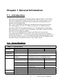
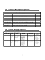
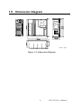
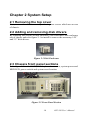
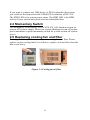
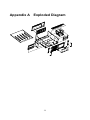
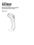
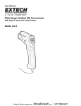
IPC-510
Industrial Chassis
User’s Manual
Copyright
Advantech Co., Ltd copyrights this documentation and the software included with this
product in 2003. All rights are reserved. Advantech Co., Ltd. reserves the right to make
improvements in the products described in this manual at any time without notice.
No part of this manual may be reproduced, copied, translated or transmitted in any form or
by any means without the prior written permission of Advantech Co., Ltd. Information
provided in this manual is intended to be accurate and reliable. However, Advantech Co.,
Ltd. assumes no responsibility for its use, or for any infringements of the rights of third
parties, which may result from its use.
Acknowledgments
IBM and PC are trademarks of International Business Machines Corporation.
On-line Technical Support
For technical support and service, please visit our support website at:
http://www.advantech.com/support
Note:
Part No. 2002051000 1st Edition
Printed on July 2003
ii
ICP-510 User’s Manual
Contents
CHAPTER 1 GENERAL INFORMATION......................................... 6
1.1 INTRODUCTION ................................................................ 6
1.2 SPECIFICATION ................................................................ 6
Table 1.1: Specification......................................... 6
1.3 PASSIVE BACKPLANE OPTIONS ....................................... 7
Table 1.2: Passive Backplane Options.................. 7
1.4 POWER SUPPLY OPTIONS................................................. 7
Table 1.3: Power Supply Options.......................... 7
1.5 DIMENSION DIAGRAM ..................................................... 8
Figure 1-1: Dimention Diagram........................... 8
CHAPTER 2 SYSTEM SETUP .......................................................... 10
2.1 REMOVING THE TOP COVER .............................................. 10
2.2 ADDING AND REMOVING DISK DRIVERS ............................ 10
Figure 2-1 Disk Enclosure .................................. 10
2.3 CHASSIS FRONT PANEL SECTIONS ..................................... 10
Figure 2-2 Front Panel Section .......................... 10
2.4 MOMENTARY SWITCH ...................................................... 11
2.5 REPLACING COOLING FAN AND FILTER ............................. 11
Figure 2-3 Cooling fan & filter............................11
APPENDIX A
EXPLODED DIAGRAM......................................... 13
APPENDIX B SAFETY INSTRUCTIONS ........................................ 16
SAFETY INSTRUCTIONS .......................................................... 16
iii
CHAPTER
1
General Information
Chapter 1 General Information
1.1
Introduction
IPC-510 is a 4U height IPC rackmount chassis which includes 14-slot ISA or
ISA/PCI backplane and within 250W ATX PFC PS/2 power supply. It is the
best price performance industrial chassis platform for building block and
mission-critical applications.
IPC-510 is with shockproof and easy installation front accessed driver bay,
three half-height 5.25”, one 3.5” FDD, one internal 3.5" HDD and front
accessible USB, PS/2 keyboard connector. For the high-density application,
IPC-510 supports versatile ISA/PCI backplane, ATX M/B version and 300W
ATX PFC power supply by options.
IPC-510 is a rack-optimized IPC chassis and offers the best total cost
ownership and scalability for customers who want to growth their business
without increasing cost. A wide range of standard computing peripherals can
be integrated with the chassis to meet different application development under
mission-critical environment 24 hours a day, 7days a week.
1.2
Specification
Table 1.1: Specification
Front-accessible
Internal
1
1
3
1(84 CFM/each)
1(front-accessible)
1(front-accessible)
Two D-SUB 9-pin brackets
LED display for power on and HDD activity
Operating
Non-Operating
0 ~ 40 ºC (32 ~ 104 ºF)
-20 ~ 60 ºC (-4 ~ 140
ºF)
Humidity
10 ~ 85%
10 ~ 95 %
Vibration (5-500 Hz)
1 Grms
2G
Shock
10 G (With 11 msec duration,
30G
1/2 sine wave)
Altitude
10,000 ft
40,000 ft
Acoustic Noise
Less than 60dB sound pressure at 5~28ºC (41~82ºF)
Dimensions (W x H x D) 482 x 177 x 450 mm (19” x 7” x 17.7”)
Weight
9.8 kg (21.6 lb)
Safety
CE compliant, UL/cUL approved
3.5”
Drive Bay
5.25”
Cooling
Fan
USB
I/O Interface
PS/2
Miscellaneous Rear panel
Indicator
Environment
Temperature
Physical
Compliance
6
ICP-510 User’s Manual
1.3
Passive Backplane Options
Table 1.2: Passive Backplane Options
B/P Model Name
Slot per Segment (ISA/PCI/CPU)
Segment
PCA-6114-0B1
32-bit, 14-slot: 14 ISA
1
PCA-6114P4-C
32-bit, 14-slot: 8 ISA, 4 PCI, 2 PICMG
1
PCA-6114P7-0D1
32-bit, 14-slot: 4 ISA, 6 PCI, 3 PICMG, 1 PCI/ISA
1
PCA-6114P10-B
32-bit, 14-slot: 2 ISA, 10 PCI, 2 PICMG
1
PCA-6114P12-0B1
32-bit, 14-slot: 1 ISA, 11 PCI, 1 PICMG/PCI, 1 PICMG
1
PCA-6114P12X-A1
64-bit, 14-slot: 1 ISA, 11 PCI, 1 PICMG/PCI, 1 PICMG
1
PCA-6113P4R-0C1
32-bit, 13-slot: 7 ISA, 4 PCI, 2 PICMG
1
PCA-6113P7X
64-bit, 13-slot: 4 ISA, 7 PCI, 2 PICMG
1
1.4
Power Supply Options
Table 1.3: Power Supply Options
Model Name
Watt
PS-250ATX-Z
250W
ATX,
PFC
1757930070
300W
ATX,
PFC
Input
Output
95 ~ 132 Vac +5V@ 27A
190 ~ 264 Vac +3.3V@20A
(Selected)
+12V@13A
[email protected]
[email protected]
+5Vsb@2A
100 ~ 240 Vac +5V@ 30A
(Full-range)
+3.3V@28A
+12V@15A
[email protected]
[email protected]
+5Vsb@2A
7
Mini-load
Safety &
MTBF
+5 V @ 0.5 A
+3.3 V @ 0.3 A
UL/CSA/TUV
/CCC
100,000
hours@25℃
(Full load)
+5 V @ 0.1 A
+3.3 V @ 0.3A
UL/CSA/TUV
100,000
hours@25℃
(Full load)
1.5
Dimension Diagram
Unit:m m [inch]
Figure 1-1: Dimension Diagram
8
ICP-510 User’s Manual
CHAPTER
System Setup
9
2
Chapter 2 System Setup
2.1 Removing the top cover
First, remove the chassis cover by releasing two screws which are on rear
of chassis.
2.2 Adding and removing disk drivers
By releasing four screws of disk enclosure, you could move disk enclosure
out of chassis and refer figure 2-1 to install or remove the necessary 5.25”
and 3.5” disk drivers.
Figure 2-1 Disk Enclosure
2.3 Chassis front panel sections
Refer figure 2-2 to find USB, PS/2 keyboard connector, system power and
HDD LED, power switch and system reset location.
Figure 2-2 Front Panel Section
10
ICP-510 User’s Manual
If you want to connect any USB device or PS/2 keyboard to the system,
you could use the front accessible USB & PS/2 connector of IPC-510.
The PWR LED is for system power status. The HDD LED is for HDD
activity. Power switch and system reset are behind the door.
2.4 Momentary Switch
Use momentary switch and by way of ATX (PS_ON) function to turn on
system ATX power supply. Please use system shutdown to turn off system
power automatic or press momentary switch for a while to turn off system
power.
2.5 Replacing cooling fan and filter
Refer figure 2-3 to find location of system cooling fan and filter. Please
replace system cooling fan if it is defective, replace or clear filter when the
dust is too heavy.
Figure 2-3 Cooling fan & filter
11
APPENDIX
A
Exploded Diagram
12
ICP-510 User’s Manual
Appendix A Exploded Diagram
13
APPENDIX
Safety Instructions
B
Appendix B Safety Instructions
Safety Instructions
1. Read these safety instructions carefully.
2. Keep this User's Manual for later reference.
3. Disconnect this equipment from any AC outlet before cleaning.
Do not use a damp cloth, liquid or spray detergents for cleaning.
4. For plug-in equipment, the power outlet socket must be located
near the equipment and must be easily accessible.
5. Keep this equipment away from humidity.
6. Put this equipment on a reliable surface during installation.
Dropping it or letting it fall may cause damage.
7. The openings on the enclosure are for air convection. Protect the
equipment from overheating. DO NOT COVER THE OPENINGS.
8. Make sure the voltage of the power source is correct before
connecting the equipment to the power outlet.
9. Position the power cord so that people cannot step on it. Do not
place anything over the power cord.
10. All cautions and warnings on the equipment should be noted.
11. If the equipment is not used for a long time, disconnect it from
the power source to avoid damage by transient over voltage.
12. Never pour any liquid into an opening. This may cause fire or
electrical shock.
13. Never open the equipment. For safety reasons, the equipment
should be opened only by qualified service personnel.
14. If one of the following situations arises, get the equipment
checked by service personnel:
a. The power cord or plug is damaged.
b. Liquid has penetrated into the equipment.
c. The equipment has been exposed to moisture.
16
ICP-510 User’s Manual
d. The equipment does not work well, or you cannot get it to
work according to the user's manual.
e. The equipment has been dropped and damaged.
f. The equipment has obvious signs of breakage.
15. DO NOT LEAVE THIS EQUIPMENT IN AN
ENVIRONMENT WHERE THE STORAGE TEMPERATURE
MAY GO BELOW -20° C (-4° F) OR ABOVE 60° C (140° F).
THIS COULD DAMAGE THE EQUIPMENT. THE EQUIPMENT
SHOULD BE IN A CONTROLLED ENVIRONMENT.
The sound pressure level at the operator’s position according to IEC
704-1:1982 is no more than 70dB(A).
DISCLAIMER: This set of instructions is given according to IEC
704-1. Advantech disclaims all responsibility for the accuracy of
any statements contained herein.
16. Any insulation on conductors inside equipment which connect
accessible metal parts or other protectively earthed parts with a
protective function to the protective earth terminal shall be identified
by the colors green and yellow at lease at the termination of the
conductors.
17. CAUTION: The computer is provided with a battery-powered
real-time clock circuit. There is a danger of explosion if battery is
incorrectly replaced. Replace only with same or equivalent type
recommended by the manufacture. Discard used batteries according
to the manufacturer's instructions.
18. The computer is provided with CD drives that that comply with
appropriate safety standards including IEC 60825.
19.Before your begin make sure the Green/Yellow wire has a
reliable connection between the metal part of the computer and
ground connector.
17