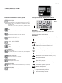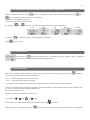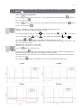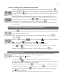
1
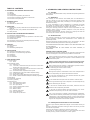
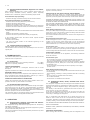
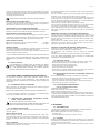
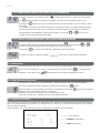
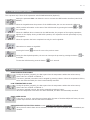
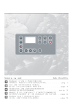
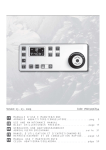
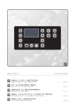
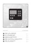
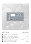
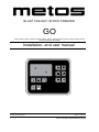
BLAST CHILLER / SHOCK FREEZER
GO
4240710, 4240712, 4240714, 4240716, 4240718, 4240720, 4240722, 4240723, 4240724, 4240725, 4240726, 4240728, 4240730,
4240732, 4240734 4240736, 4240738
Installation- and user manual
UV
7NU0311GG53-GO
+3°C
-18°C
pre
cool
start
stop
so f t
REV: 14/03/12
Käänös valmistajan englanninkielisestä ohjeesta
EN - 3
TABLE OF CONTENTS
1. STANDARDS AND GENERAL INSTRUCTIONS
1.1. Testing
1.2. Warranty
1.3. Introduction
1.4. Prerequisites supplied by the customer
1.5. Instructions regarding requests for intervention
1.6. Instructions for spare parts
2. TECHNICAL DATA
2.1. Noise level
2.2. Materials and fluids used
3. OPERATION
3.1. Applications, purpose, declared and non-declared use, authorised use
3.2. Dangerous areas, risks, hazards and avoidable risks
3.3. Safety devices
4. ROUTINE AND PROGRAMMED MAINTENANCE
4.1. Elementary safety standards
4.2. Instructions regarding emergency operations in the case of fire
4.3. Cleaning the machine
4.4. Periodic checks
4.5. Precautions in the case of extended periods of inactivity
4.6. Extraordinary maintenance
5. DISPOSAL
5.1. Disconnection
5.2. Storage
5.3. Dismantling and disposal
6. INSTALLATION
6.1. Transport and handling of the product
6.2. Description of commissioning operations
6.3. Positioning
6.4. Connection
6.5. Re-installation
7. USER INSTRUCTIONS
7.1. Control panel
7.1.1. Clock
7.2. Operational cycles
7.2.0. Switching on
7.2.1. +3ºC soft or hard blast chill cycle and soft or hard -18ºC
shock freeze with core probe
7.2.2. +3ºC soft or hard blast chill cycle and soft or hard -18ºC
shock freeze with timer
7.2.3. Customised blast chill/shock freeze cycles
7.2.4. Indefinite time cycle with cabinet setpoint setting
7.2.5. Conservation phase
7.2.6. Memorising a blast chill/shock freeze programme
7.2.7. Recall of memorised blast chill/shock freeze programme
7.3. Defrosting
7.4. Sterilisation (optional)
7.5. Printer (optional)
7.6. Alarms/errors
7.6.1. High temperature alarm
7.6.2. Low temperature alarm
7.6.3. Door open alarm
7.6.4. Pressure switch/electric alarm
7.6.5. Time-out alarm
7.6.6. Blackout alarm
7.6.7. Cabinet probe alarm
7.6.8. Core probe alarm
7.6.9. Evaporator probe alarm
1. STANDARDS AND GENERAL INSTRUCTIONS
1.1. TESTING
The product is dispatched after visual, electrical and operating tests have
been passed.
1.2. WARRANTY
The warranty on the machine and related parts we manufacture is
valid for a period of 1 year from the date of invoice and consists of the
free supply of spare parts which, according to our final judgement, are
deemed to be faulty.
It is the responsibility of the manufacturer to eliminate any faults
and defects on condition that the machine has been correctly used in
accordance with the instructions provided in the manual.
During the warranty period the customer will be responsible for costs
related to labour, travel or transfers, transport of the parts and any
equipment to be replaced.
The items replaced under warranty remain our property and must be
returned by the customer at the his own expense.
1.3. INTRODUCTION
This manual is intended to provide all the necessary information for
correct installation, operation and maintenance of the machine by
qualified personnel.
Read the instructions provided carefully prior to any operation, as these
contain essential safety indications concerning the machine.
THE MANUFACTURER DECLINES LIABILITY FOR NON-DECLARED USE
OF THE PRODUCT.
THE REPRODUCTION OF THIS MANUAL OR PARTS THEREOF, IS
PROHIBITED.
GENERAL SAFETY INSTRUCTIONS
The manufacturer declines all liability for any operation performed on the
machine in disregard of the instructions provided in this manual.
Before connecting the machine to the power supply, ensure that
the voltage and frequency correspond to those indicated on the
specifications plate.
Always connect the machine to an appropriate high sensitivity differential magnet circuit breaker switch (30 mA).
Before performing any cleaning or maintenance operation disconnect the machine from the power supply by:
1) Positioning the master switch on OFF;
2) Removing the plug.
Wear gloves to perform maintenance on the motor compartment or
on the evaporating unit positioned inside the machine.
Do not insert screwdrivers or other devices between the guards
(fan evaporator protections etc.).
Do not handle electrical parts with wet hands or without shoes.
Ensure good functioning of the compressor unit and evaporator by
never obstructing the air inlets.
In the case of machines fitted with wheels, check that the rest
surface is flat and perfectly horizontal.
In the case of machines fitted with locks and keys, it is recommended to keep the keys out of the reach of children.
Use is only reserved for suitable, trained personnel. Installation,
routine and extraordinary maintenance (for example, cleaning and
maintenance of the refrigerating system), must be performed by
specialised and authorised technical personnel with a sound knowledge of the refrigeration and electrical systems.
1.4. PREREQUISITES SUPPLIED BY THE CUSTOMER
Provide a high sensitivity differential magnet circuit breaker switch (30
mA).
Provide a wall socket with earth of the type used in the country in which
the machine is operated.
verify that the surface on which the machine rests is level.
In the case of water-cooled machines or with equipment with direct
humidity control, provide connection to a water system.
4 - EN
1.5. INSTRUCTIONS REGARDING REQUESTS FOR INTERVENTION
Often operating difficulties are a result of ordinary causes which are
almost always remediable inhouse, therefore, before requesting
assistance from a technician, perform the following simple checks.
If the machine stops operating:
- check that the plug is inserted correctly into the electrical socket.
If the cabinet temperature is insufficient:
- check that this is not being affected by a heat source;
- check that the doors close perfectly;
- check that the condenser filter is not blocked;
- check that the ventilation grills of the control panel are not obstructed;
- check that the items inside the cabinet are not obstructing ventilation.
If the machine is noisy:
- check that there is no loose contact between the machine and another
object;
- check that the machine is perfectly level;
- check that the screws (at least those visible) are tightened;
If the problem persists after the above checks request technical
assistance, indicating:
- the nature of the defect;
- the code and serial number of the machine appearing on the
specifications plate.
1.6. INSTRUCTIONS FOR SPARE PARTS
ORIGINAL SPARE PARTS ARE RECOMMENDED.
The manufacturer does not accept any responsibility for the use of nonoriginal parts.
APPLICATION OF THE BLAST CHILLER-SHOCK FREEZER
The blast chiller-shock freezer is a machine which rapidly lowers the
temperature of cooked or raw foods, in order to maintain the organoleptic
properties (chemical-physical and nutritional) of these foods unaltered.
COOLING OR FREEZING TIME IS A PARAMETER THAT IS DIFFICULT TO
ESTABLISH WITH ANY PRECISION, SINCE THIS DEPENDS ON THE TYPE
OF FOOD OR FOODS IN A COOKED DISH.
THE DECLARED PERFORMANCE LEvELS WERE OBTAINED BY USING
POTATO PURÉE IN OFF THE SHELF ALUMINIUM TRAYS GN1/1 H=40.
THE THICKNESS OF THE MASHED POTATOES INTO THE CONTAINERS
IS 25mm.
Blast chilling temperature cycle
This cycle enables rapid lowering of the temperature of the cooked food
(from +90 to +3°C in 90 minutes) to avoid it remaining within the critical
temperature range of +10°C to +65°C.
The cooked and blast chilled food can be stored in the refrigerator for
up to 5 days.
Shock freezing temperature cycle
Shock freezing (from +90°C to -18°C) prevents the formation of macrocrystals of ice in the food, which would result in a loss of liquids and
vitamins. This cycle is suitable for cooked and raw food and conserves
these foodstuffs for up to 2 months and 12 months respectively.
Conservation cycle
At the end of every blast chilling or shock freezing cycle the machine
envisions a conservation cycle during which the equipment functions as
a normal refrigerator and the duration of which is at the user’s discretion.
FOODSTUFFS STORAGE
For the best performance of the appliance, the following indications
should be observed.
2. TECHNICAL DATA
The technical data plate is located outside on the side or at the rear and
inside the motor compartment.
2.1. NOISE LEVEL
Leq at the noisiest point at 1m in operating conditions
Lpc at 1m in operating conditions
Avoid the appliance misuse. Do not introduce into the cell: live animals,
objects or corrosive products.
< 70 dB(A)
< 130 dB(C)
TESTING ENVIRONMENT
Testing was performed in a rectangular showroom with no sound
absorption.
Significant obstacles were absent in the area surrounding the machine.
REFERENCE REGULATIONS
Noise testing was performed in compliance with Legislative Decree 277
and in accordance with methods described in ISO 230-5, in order to
obtain the data required by 2006/42/EC Directive.
OPERATING CONDITIONS OF THE MACHINE
Testing was performed under the most severe condition which corresponds to the start-up phase called “PULL DOWN”.
Conservation cycle:
- do not introduce hot foods or uncovered liquids inside the machine;
- wrap or protect foodstuffs, particularly if they contain aromas;
- Arrange the foodstuffs inside so as not to limit air circulation, avoiding
placing papers, cartons, boards, etc. on the racks, which may obstruct
the passage of air;
- as far as possible, avoid opening the door frequently or for lengthy
periods of time.
Blast chilling/shock freezing cycle:
- do not open the door once the cycle has commenced and until the cycle
has terminated;
- avoid wrapping, protecting or closing containers with lids or insulating
films;
- do not use trays or containers taller than 65mm;
- do not stack foodstuffs;
- use aluminium or stainless steel containers.
2.2. MATERIALS AND FLUIDS USED
Respecting the environment, all the used materials comply with Legislative Decree no.151, July 25, 2005, in the implementation of directives
RoHS (2002/95/EC) and WEEE (2002/96/EC and 2003/108/EC), concerning to the reduction in use of hazardous substances in electrical and
electronic equipment as well as waste disposal.
The refrigerant gases or the foaming agents of the polyurethane foams
used are in compliance with Regulation EC 842/2006.
3.2. DANGEROUS AREAS, RISKS, HAZARDS AND AVOIDABLE RISKS
The refrigerator equipment has been designed and manufactured with
the appropriate devices to guarantee the health and safety of the user
and does not contain dangerous edges, sharp surfaces or protruding
elements.
The stability of the machine is guaranteed even when the doors are
open; however, do not pull on the doors.
In the case of refrigerators with drawers, do not open more than one
drawer at a time and do not lean or sit on an open drawer, so as to avoid
overturning or damaging the refrigerator.
3. OPERATION
N.B.: In refrigerators with glass doors do not extract more than one
basket or rack at a time so as not to compromise the stability of the
refrigerator. Gradually arrange the foodstuff starting from the bottom
upwards; similarly, remove foodstuff starting from the top downwards.
3.1. APPLICATIONS, PURPOSE, DECLARED AND NON-DECLARED USE, AUTHORISED USE
Our refrigerators are agri-food machines (EC regulation No. 1935/2004),
intended for foodstuffs.
The machines are designed with the appropriate equipment to guarantee the health and safety of the user.
They are not suitable for storing pharmaceuticals, chemicals or any other
non food products.
THE MACHINE HAS NOT BEEN DESIGNED TO BE INSTALLED IN AN EXPLOSIvE ATMOSPHERE.
MAXIMUM LOAD (UNIFORMLY DISTRIBUTED) PER BASKET, DRAWER
OR RACK = 40 KG
APPLIANCE WITH WHEELS
When moving, take care not to forcefully push the refrigerator so as
EN - 5
avoid overturning and damage. Also note any unevenness of the surface
on which the refrigerator is being pushed. Appliances fitted with wheels
cannot be levelled, therefore, ensure that the surface on which they rest
is perfectly horizontal and level.
ALWAYS BLOCK THE WHEELS WITH THE STOPS PROvIDED.
RISKS CAUSED BY MOVING PARTS
The only moving part is the fan, which presents no risk as it is isolated by
a protection grill secured with screws (before removing this protection,
disconnect the machine from the power supply).
RISKS CAUSED BY LOW/HIGH TEMPERATURES
Adhesive labels indicating “TEMPERATURE WARNING” are located in the
proximity of areas which constitute low/high temperature dangers.
RISKS CAUSED BY ELECRICAL POWER
Electrical risks have been eliminated by designing the electrical system
in accordance with IEC EN 60204-1 and IEC EN 60335-1. Adhesive labels
indicate “high voltage” areas which may present electrical risks.
RISKS CAUSED BY NOISE
Leq at the noisiest point at 1m in operating conditions
Lpc at 1m in operating conditions
< 70 dB(A)
< 130 dB(C)
RESIDUAL RISKS
Any liquids emanating from foodstuffs or washing products are prevented
from leaking outside by a drain positioned at the bottom.
During cleaning operations, remove the plug and place a collection tray
under the machine (Hmax=100mm).
IT IS OF UTMOST IMPORTANCE THAT THE PLUG IS REFITTED IN THE
HOLE. IN THE CASE OF MACHINES WITH NO DRAIN, PREvENT THE
STAGNATION OF LIQUIDS BY CLEANING THOROUGHLY ON A DAILY
BASIS.
3.3. SAFETY DEVICES
IT IS PROHIBITED TO TAMPER WITH OR REMOvE THE SAFETY
DEvICES PROvIDED (PROTECTION GRILLS, DANGER LABELS,
ETC.). THE MANUFACTURER DECLINES ALL LIABILITY SHOULD
THE SAID INSTRUCTIONS NOT BE RESPECTED.
4. ROUTINE AND PROGRAMMED MAINTENANCE
The information contained in this chapter addresses suitable, trained
personnel in the case of routine maintenance; while specialised and
authorised personnel is addressed for extraordinary and/or programmed
maintenance.
4.1. ELEMENTARY SAFETY STANDARDS
Before performing any intervention, disconnect the machine plug from
the electrical mains power supply.
REMOvAL OF PROTECTIONS OR SAFETY DEvICES IS PROHIBITED.
In routine maintenace operations, the removal of protections/saftey
devices (grills, adhesive labels, etc.) is prohibited.
4.2. INSTRUCTIONS REGARDING EMERGENCY OPERATIONS IN THE CASE OF FIRE
DO NOT USE WATER IN THE CASE OF FIRE.
USE CO2 FIRE EXTINGUISHER (CARBON DIOXIDE) AND COOL THE
MOTOR COMPARTMENT AREA AS QUICKLY AS POSSIBLE.
4.3. CLEANING THE MACHINE
Before any cleaning operation, disconnect the machine from the electrical power supply.
INITIAL INSTALLATION
Before operating, wash the interior and accessories with a little water
and neutral soap in order to remove the characteristic “new” odour. Arrange the accessories inside the cabinet in positions most appropriate
for use.
DAILY CLEANING
Carefully clean the external surfaces of the machine using a damp cloth
and following the direction of the finish.
Use neutral detergents and not substances with a chlorine base and/or
that are abrasive.
Do not use utensils which may cause scratches and consequently the
formation of rust. Rinse with clean water and dry carefully.
Clean the interior of the cabinet with neutral detergents which do not
contain chlorine or abrasives, to avoid the formation of dirt residues. In
the case of hardened residues, use soap and water or neutral detergents,
using a wooden or plastic spatula if necessary.
After cleaning, rinse with a little water and dry carefully.
Do not wash the machine with direct water jets, as any water leakage
into electrical components may affect their correct functioning.
Lower and adjoining areas of the machine must also be cleaned on a
daily basis with soap and water and not with toxic or chlorine-based
detergents.
WARNINGS FOR BLAST CHILLERS WITH WASHING KIT
Always use the neutral detergent supplied by the manufacturer so to
guarantee maximum cleanliness without damaging the interior surface
and the relative functional parts of the blast chiller (evaporator, fans,
heating plant, etc).
Before starting nay washing program check, using the visual indicator
positioned in the lower left side of the appliance, that the level of
detergent is above the minimum accepted.
PERIODIC CLEANING AND GENERAL MAINTENANCE
Cleaning and general maintenance operations must be carried out to
ensure the consistent performance of the machine.
The refrigerator unit (condenser) must be cleaned by specialised
personnel.
Regularly clean the drain to avoid that the hole becomes blocked.
IT IS OF UTMOST IMPORTANCE THAT THE HOLE IS CLOSED ONCE
AGAIN WITH THE APPROPRIATE PLUG.
-
4.4. PERIODIC CHECKS
Check that the plug is correctly inserted in the power supply socket.
Check that the appliances are not affected by heat sources.
Check that the machine is perfectly level.
Check that the door gasket seals perfectly.
Check that the drain is not blocked.
Check that the condenser battery is not covered with dust; should this
be the case, request after-sales technical assistance.
4.5. PRECAUTIONS IN THE CASE OF EXTENDED PERIODS OF
INACTIVITY
If an extended period of inactivity of the machine is foreseen:
- switch the machine off by pressing the OFF button on the control panel;
- remove the plug from the power supply socket;
- empty the refrigerator and carefully clean it (see cleaning section);
- leave doors ajar to ensure air circulation.
4.6. EXTRAORDINARY MAINTENANCE
(only by specialised personnel)
Periodically clean condenser.
Check door gaskets to ensure perfect sealing.
Check that the electrical system is in order.
Check the surround heating elements (using an amperometric clamp).
IN THE CASE OF REPAIRS OR REPLACEMENT OF PARTS, ALWAYS PROvIDE THE CODE AND SERIAL NUMBER OF THE MACHINE, vISIBLE ON
THE SPECIFICATIONS PLATE.
5. DISPOSAL
5.1. DISCONNECTION
The disconnection operations must be done by qualified technicians.
Avoid spilling or leakage into the environment.
Before disconnecting the unit collect, if there are any:
- refrigerant gas;
- non-freezing solutions present in hydraulic circuits.
5.2. STORAGE
Waiting for dismantling and disposal, the appliance can be temporarily
stored outdoor provided that the unit electrical, refrigeration and plumbing circuits are intact and closed.
However country’s laws on environmental protection are still to be observed.
6 - EN
5.3. DISMANTLING AND DISPOSAL
This symbol identifies the units as returning units, in
directive RAEE 2002/96/CE.
Information regarding potential effects on environment
and human health, due to the presence of hazardous
substances, can be obtained from the manufacturerdistributor-importer, as in charge of collecting and processing the waste, or from the retailer where you purchased the appliance, or from the local services in charge of waste disposal.
DISMANTLING OPERATION MUST BE DONE BY QUALIFIED PERSONNEL.
Disposal
WEEE Directive requires that electrical and electronic equipment disposal
and recycling must be handled through a dedicated collection, in suitable approved facilities, and in a separate way from the on one done for
mixed domestic waste disposal.
The user has the obligation of not disposing of the appliance at the end
of the useful life of the same, as a domestic waste, but to deliver it to
designated collection facilities authorized as required by regulations or
specified by the distributor.
All materials are to be retrieved or disposed of in compliance with the
national regulations concerning the subject.
For further information on the appliance disposal: contact the manufacturer.
6. INSTALLATION
(only by specialised technical personnel)
6.1. TRANSPORT AND HANDLING OF THE PRODUCT
The machine must be transported using suitable handling equipment
and never manually.
If lifting systems are used, such as a forklift or transpallet, take particular
care that the load is balanced.
Normally the packaging is in expandable polystyrene on wood pallets,
secured to the bottom of the equipment for greater safety during
transport and handling.
Warnings are printed on the packaging, representing the instructions to
be complied with to ensure that no damage is caused during loading and
unloading operations, transport or handling.
Warnings printed on our packaging:
TALL LOAD
FRAGILE
KEEP DRY
The user must dispose of the packaging in accordance with the laws in
force in the applicable country.
STACKING LIMITS
When storing or transporting the machine, the maximum stacking limit is
two machines, unless otherwise indicated with an appropriate adhesive
label.
SINCE THE CENTRE OF GRAvITY OF THE MACHINE DOES NOT
CORRESPOND TO ITS GEOMETRIC CENTRE, BE AWARE OF
INCLINATIONS DURING HANDLING.
6.2. DESCRIPTION OF COMMISSIONING OPERATIONS
After removing the packaging from the machine, it is advisable to verify
the integrity of the machine and the absence of damage due to transport.
Any damage must be communicated to the carrier immediately.
Damaged machines cannot be returned to the manufacturer under any
circumstances without prior notice and written authorisation is received.
DURING HANDLING DO NOT PUSH OR DRAG THE MACHINE TO
PREvENT OvERTURNING OR DAMAGE TO PARTS (E.G. FEET).
NEvER LEAN THE MACHINE ON THE DOOR SIDE.
6.3. POSITIONING
Position the machine in a well-aerated place and far from heat
sources. Observe minimum gaps for operating functions, aeration and
maintenance.
MACHINE WITH WHEELS
A machine with wheels cannot be levelled, therefore, ensure that the
surface on which it rests is perfectly horizontal and level.
AFTER HAvING POSITIONED THE MACHINE, ALWAYS BLOCK THE
WHEELS.
DURING HANDLING DO NOT PUSH FORCEFULLY OR DRAG THE
MACHINE TO PREvENT OvERTURNING OR DAMAGE.
PAY PARTICULAR ATTENTION TO UNEvENNESS OF SURFACES.
NEvER LEAN THE MACHINE FROM THE DOOR SIDE.
THE MACHINE HAS NOT BEEN DESIGNED TO BE INSTALLED IN
EXPLOSIvE ENvIRONMENTS.
6.4. CONNECTION
Before connecting the machine to the power supply, ensure that
the voltage and frequency correspond with those indicated on the
specifications plate.
A variation of +/-10% of the normal voltage is permitted.
It is of utmost importance that the machine is connected to an efficient
earth connection.
WARNINGS FOR BLAST CHILLERS WITH WASHING KITS
The appliance must be connected to the water supply network using the
supplied flexible pipe, suitable for high temperatures and pressure and
with ¾” GAS attachment.
To prevent the excessive deposit of lime scale and therefore decrease
plant maintenance the use of a water softener is recommended.
To increase efficiency the recommended water temperature must be
between 40-60°C. The optimum network pressure must be between 2-5
bar for the rotor to rotate regularly. If the water pressure should fall
below 0.5 bar a safety pressure switch will intervene that will immediately
block the function, with signal on the alarm display.
For blast chillers with washing kit
IT IS FUNDAMENTAL NOT TO CHANGE THE DIRECTION OF THE
ROTOR SPRAYING NOZZLES SO AS NOT TO COMPLETELY ALTER
THE SYSTEM FUNCTIONING FEATURES.
DO NOT USE PLUGS WITHOUT EARTH. THE MAINS SOCKET MUST
COMPLY WITH REGULATIONS vALID IN THE APPLICABLE COUNTRY.
EARTHING THE MACHINE IS A MANDITORY SAFETY MEASURE
BY LAW
In order to protect the machine from any electrical overload or shortcircuits, the connection to the power supply is through a high sensitivity
differential magnet circuit breaker switch (30 mA) with manual re-set
and with sufficient power.
For dimensioning the protection device, consider the following:
Imax = 2.3 In (nominal current)
Icc (short-circuit current) = 4500 A with 230v/1~/50Hz power supply.
Icc (short-circuit current) = 6000 A with 400v/3~/50Hz power supply
6.5. RE-INSTALLATION
If a re-installation is necessary, proceed as follows:
1) Position the power supply switch on OFF;
2) Disconnect the plug from the power supply and wind up the cable;
3) Remove all foodstuff from the interior of the cabinet and clean the
cabinet and accessories thoroughly;
4) Re-pack the machine, taking care to re-position the protective
polystyrene and secure the wooden base, in order to prevent damage
during transport;
5) Proceed as described previously for the new positioning and
connection.
EN - 7
7. USER INSTRUCTIONS
7.1. CONTROL PANEL
Description buttons of control panel
UV
+3°C
-18°C
pre
cool
start
stop
so f t
Description of the display and symbols
START/STOP
After having connected the machine to the power supply,
press this button to progress the machine from a state of
inactivity (Off) to one of Stand-by, in preparation for setting
the desired cycle
This button is also used to start/interrupt operation during
the blast chill/shock freeze/conservation cycle
DISPLAY 1
DISPLAY 3
UP
Increase values, displays the temperature of the core probe
DOWN
Decrease values, displays cycle time elapsed
+3°C BLAST CHILL
Selection of blast chill at +3°C
–18°C SHOCK FREEZE
Selection of shock freeze at -18°C
SOFT
Selection of soft blast chill cycle (+3°C) or shock freeze
(-18°C)
DEFROST
Start/stop defrost
By pressing the button for extended time, the temperature
of the evaporator probe is displayed
PROBE HEATING
DISPLAY 2
DISPLAY 1
Displays temperature of the core probe or time
DISPLAY 2
Displays temperature of the cabinet
DISPLAY 3
Displays the operational phase in progress (from 1 to 3)
Cabinet temperature
Heating active core probe
Blast chill/shock freeze cycle with core probe
(flashing in core probe insertion test)
Blast chill/shock freeze cycle with timer
Sterilisation in progress
Blast chill cycle function selected (+3°C)
Shock freeze cycle function selected (-18°C)
Heating for extraction of core probe
Soft phase selected
STERILISATION
Start/stop sterilisation process
PROGRAMME
Memory or recalls a blast chill/shock freeze cycle on memory
PROGRAMME
Start/stop the precooling cycle of the room
Blast chill in progress
(flashing when active compressor delay)
Conservation phase in progress
Machine in Stop mode
Compressor activity indicator
Room fans activity indicator
8 - EN
GENERAL RECOMMENDATIONS
For correct use of the spike probe:
- avoid violent blows, they can jeopardise the correct
functioning of the probe;
- sterilise the spike before use;
- the maximum recommended thickness of the product
is 45mm;
- cleanliness of the spike determines good performance.
H max = 45mm
TO INSERT THE PROBE
- Insert the probe with the point as near as possible to
the heart of the product.
H
45mm
single point-probe
TO EXTRACT THE PROBE
see 7.2.5.
- Heat the probe
- Turn it.
- Extract it without tilting the spike.
H
45mm
H
45mm
H
45mm
EN - 9
7.1.1. CLOCK (with optional expansion card for printer or supervision)
button, it is possible to change the clock setting by keeping the
With the machine turned off by the
and
buttons pressed simultaneously for extended time.
• DISPLAY 1 indicates the year value
• DISPLAY 2 indicates the letters “Year”
and
By using the
buttons it is possible to change the values of the respectively:
year
Use button
Press
month
day
hours
minutes
to confirm the value, which is displayed thereafter.
button to exit.
7.2.0. SWITCHING ON
button the board turns on, no selection is visible in DISPLAY 1 (Fig.1), DISPLAY 2
By pressing the
indicates the cabinet temperature and the Stop symbol.
(Fig.1)
7.3.0.1 PRECOOLING
After having selected a blast chilling or freezing cycle (even already executed), pressing the button
PreCooling cycle that takes the room temperature to:
-10°C
-25°C
activates a
if a blast chilling cycle has been selected
if a freezing cycle has been selected
If no cycle has been selected previously, the room behaves as if a freezing cycle has been selected.
Once the PreCooling SetPoint has been reached, the Buzzer sounds for 3 seconds every 60 seconds to indicate that
the room is ready to execute the blast chilling cycle.
During the PreCooling cycle:
DISPLAY 2 shows the temperature of the room.
The symbols
,
and
or
are lit.
At the start of the compressor and fan, the respective symbols
Opening the door or pressing the button
are also lit.
interrupts the cycle, and the card reproposes the last cycle selected.
10 - EN
7.2.1. +3ºC SOFT OR HARD BLAST CHILL CYCLE AND -18ºC SOFT OR HARD SHOCK FREEZE
CORE PROBE
BLAST CHILL/SHOCK FREEZE PHASE
Press the
button to select the +3ºC hard blast chill cycle and also the
for the +3°C soft cycle
Press the
(Fig.2)
.
button to select the -18ºC hard shock freeze cycle and also the
-18°C soft cycle
(Fig.4)
button for the
.
The following symbols light up: core probe
(Fig.3)
button
soft or shock freeze hard
, or soft
, type of blast chill soft
or soft
+ the symbol soft ,temperature
+ the symbol
and
(Fig.2).
To start the selected cycle press the
button; the blast chill in progress symbol
lights up
(Fig.3). Within the first 3 minutes, the electronic control performs a core probe insertion test to
verify the effective application of the probe in the product to blast chill; the core probe symbol
flashes in this phase.
If the core probe is inserted badly or left in the holder provided, the cycle is automatically converted
to “timer” and DISPLAY 1 indicates the time to the end of the blast chill cycle (Fig.4).
The following symbols light up:
, blast chill function
, temperature
, compressor
,
room fan
and blast chill symbol
. DISPLAY 2 indicates the cabinet temperature and DISPLAY
3 the blast chill phase in progress.
If the temperature has not been reached through to the core within the time determined, with blast
chill/shock freeze core probe confirmed, the time out alarm is activated. The blast chill phase contisymbol flashes.
nues but the
On DISPLAY 1 the code AL5 flashes (Fig.5). The alarm remains on into the conservation phase.
(Fig.5)
By pressing the
button at any time during the cycle in progress, the time from the start of
blast chilling is indicated.
Upon termination of the blast chill cycle the machine automatically continues on to the conservation
phase, see 7.2.5.
By pressing the
button is indicated the time of the concluded blast chilling cycle.
+3 SOFT
+3 HARD
-18 SOFT
-18 HARD
EN - 11
7.2.2. +3ºC SOFT OR HARD BLAST CHILL CYCLE AND -18ºC SOFT OR HARD SHOCK FREEZE
TIMER
BLAST CHILL/SHOCK FREEZE PHASE
Press the
button twice to select the +3ºC hard blast chill cycle and also the
button for
.
the +3°C soft cycle
button twice to select the -18ºC hard shock freeze cycle and also the
Press the
for the -18°C soft cycle
button
.
DISPLAY 1 indicates the total time foreseen for blast chilling/shock freeze.
DISPLAY 2 indicates the cabinet temperature (Fig.6).
(Fig.6)
The following symbols light up: time
soft or shock freeze hard
, or soft
, type of blast chill hard
or soft
+ the symbol soft, temperature
+ the symbol
and
.
By using the
or
buttons it is possible to change the cycle duration.
N.B.: It is possible to set a duration either shorter or longer that 90 min. for blast chill cycles or 240
min. for shock freeze cycles.
Maximum limit: 120 min. for a +3°C cycle
Maximum limit: 300 min. for a -18°C cycle
Press the
(Fig.7)
button to start the cycle.
By pressing button
(Fig.7) the temperature read by the probe is temporarily displayed (if inserted into the product, it will show the temperature of this product).
Upon termination of the blast chill cycle the machine automatically continues on to the conservation phase, see 7.2.5.
By pressing the
button is indicated the time of the concluded blast chilling cycle.
+3 SOFT
+3 HARD
-18 SOFT
-18 HARD
12 - EN
7.2.3. BLAST CHILL OR SHOCK FREEZE PERSONALIZE CYCLE ,
,
It is possible to modify the breakdown/freezing cycle:
- timed
- probe
,
personalising them as required.
The breakdown or freezing cycle is divided into three phases where it is possible to modify the following values:
IN ORDER TO MODIFY THE DATA IN NOT PERMANENT WAY
Press the key relative to the cycle
(+3 hard), or the key
For the soft cycles, first press the
button and then press and hold the button
(-18 hard)
or
.
Control displays (Fig. 8):
SCREEN 1- modifiable cell temperature
SCREEN 2 - no signal (off)
SCREEN 3 – the number of the phase
(Fig.8)
The cell temperature symbol
flashes, by pressing the
or
the value of the set temperature is increased or decreased, for the phase being modified and displayed on DISPLAY 3.
With a further pressing the “initially selected cycle” the pin symbol flashes
, by pressing the
or
the value of the set pin temperature is increased or decreased, for the phase being
modified and displayed on DISPLAY 3.
symbol flashes, by pressing the
With a further pressing the “initially selected cycle” the clock
or
the value of the set duration is increased or decreased, for the phase being modified
and displayed on DISPLAY 3.
Repeat the same procedure described for the later phases 2 and 3.
Phase 4 of conservation only involves setting the set temperature. To confirm the settings of all the
phases described, press the relevant key
or
for extended time.
Press the
button to start the cycle.
At the end of the cycle the machine moves into conservation phase automatically, see ch. 7.2.5.
The new sets of the personalised cycle will be lost when the machine is stopped with key
See tecincal manual
S _ _ = setpoint
BLAST CHILL OR SHOCK FREEZE
CONSERvATION
PHASE 1
PHASE 2
PHASE 3
PHASE 4
SET CABINET
S01
S04
S07
S10
SET CORE
S02
S05
S08
--
SET TIME
S03
S06
S09
--
.
EN - 13
7.3.5.1 TO STORE DATA IN A PERMANENT PROGRAMME
After the modification procedure described above (cap 7.2.3), press and hold the button
rather than
(Fig.8a)
or
; DISPLAY 1 shows the number of the first available programme. Pressing
and holding the button
stores the cycle, and the control positions itself to restart with a new
cycle (Fig. 8a).
A stored programme can be deleted by overwriting a new blast chilling/freezing cycle on it as
follows: at the end of the cycle, instead of storing it on the first available programme automatically
selected by the system, press the button
(Fig.8b)
or
and position the display on the number
of the programme to be deleted, then press the programme button
.
If the symbols _ _ _ appear on DISPLAY 2 next to the number, this means that no programme is
stored (Fig. 8b).
7.2.4. INDEFINITE TIME CYCLE WITH CABINET SET POINT SETTING
programme button to exit any programme; press the button once again and DISPLAY
Press the
1 will indicate the letters P0 (Fig.9).
(Fig.9)
Select a blast chill/shock freeze programme with the appropriate buttons +3°C hardt
.
–18°C hard
with the clock symbol
DISPLAY 1 indicates symbol
(Fig.10)
or
next to it, the type of blast chill
or shock freeze
, the temperature symbol
and
.
DISPLAY 2 indicates the default temperature of the selected cycle: (Fig.10).
Buttons
and
DISPLAY 2. Button
increase or decrease the set point cabinet temperature value indicated in
starts the machine. To stop the machine press the
button.
7.2.5. CONSERVATION PHASE
At the end of each blast chill/shock freeze cycle, the machine proceeds to conservation phase.
DISPLAY 1 is off; DISPLAY 2 indicates the cabinet temperature (Fig.11).
(Fig.11)
The conservation symbol
By pressing the
lights up.
button is indicated the time of the concluded blast chilling cycle.
By pressing button
the temperature read by the probe is temporarily displayed (if inserted into
the product, it will show the temperature of this product).
This phase is terminated by pressing the
button. The machine sets itself on Stand-by and the user
is asked whether the programme is to be memorised or the button
Press the core probe heating button
must be pressed once more.
to facilitate extraction of the probe from the product.
The
symbol lights up.
Core probe heating takes place only if the temperature of the probe is less than -5ºC.
14 - EN
7.2.6. MEMORISING A BLAST CHILL/SHOCK FREEZE PROGRAMME
With the machine in conservation mode
the
(Fig.12)
(if the cycle has gone to good aim) and pressing
button, DISPLAY 1 indicates the number of the first free programme (Fig.12), by
pressing the
button, the cycle is memorised and the control board is re-set in order to start a
new cycle.
It is possible to cancel a memorised programme overwriting it with a new blast chill/shock freeze
cycle by doing the following: once a cycle has terminated, instead of memorising it in the first
free programme automatically selected by the system, use button
number of the programme to be cancelled.
or
to access the
7.2.7. RECALL OF MEMORISED BLAST CHILL/SHOCK FREEZE PROGRAMME
To select a blast chill/shock freeze programme press button
. By pressing the
buttons the memorised programmes are displayed in sequence (Fig.13).
(Fig.13)
Press button
or
to start the selected blast chill/shock freeze programme.
If DISPLAY 2 (Fig.14) indicates symbols
there are no memorised programmes.
(Fig.14)
7.3. DEFROSTING
Manual defrosting with the door open is performed if the cabinet temperature is below parameter
P57 (see tecincal manual). To start or stop defrosting cycle press button
(Fig.15)
DISPLAY 1 will indicate code
for extended time.
and DISPLAY 2 the cabinet temperature (Fig.15).
7.4. STERILISATION (OPTIONAL)
Sterilisation can start only if the temperature is above parameter P26 (see tecincal manual).
The cycle is activated with the machine in Stand-by by pressing the
(Fig.16)
When the button is pressed again, sterilisation is terminated. The symbol
indicates that the sterilisation phase is in progress.
DISPLAY 1 shows the time to the end of the process (Fig.16).
If the door is opened or a blackout occurs, sterilisation terminates.
button.
light up on the display
7.5. PRINTER (OPTIONAL)
The following is recorded for every blast chill cycle: date, time, type of cycle, time elapsed from start and temperature in the cabinet and at the product’s core, sampled every 10 minutes, to modify the sampling time see parameter
P44 (see tecincal manual).
Using parameter P72 (see technical manual) the language of the printer can be changed.
****HELLO****
03/03/2007
+3°C HARD
Time
00:00
00:10
00:20
10:15
Ti
25
8
-5
Tc
61
54
T i m e = time elapsed
T i = CABINET temperature
T c = CORE temperature
EN - 15
7.5.1 USB Recorder (optional)
This is present only if there is the expression code EVC99E00X0XXX00 (Optional).
Setting the parameter P41 = 2 allows the user to connect the USB Recorder interface (code EVUS
BREC01).
When the keypad detects the presence of the USB Recorder, the user can access the USB menu which provides information on the state of the USB Recorder by pressing the buttons
for 2 seconds:
or
When the USB flash drive is inserted in the USB Recorder, the progress of the ongoing operations appears on the display. During a LOG DATA operation, the respective text with percentage of prog
ress appears:
When the operation has been completed correctly, the end is signalled:
Otherwise error states are signalled:
Pressing the button
returns the user to the previous menu.
During the data Upload operation, the user can interrupt the process by pressing the button
2 seconds.
To reset the USB Recorder, press the button
for for 2 seconds.
7.6. ALARMS/ERRORS
HIGH TEMPERATURE ALARM
During the positive (negative), the alarm part when the temperature cabinet the values sets up.
Alarm code AL1 will flash on DISPLAY 1.
The buzzer (optional) sounds but can be stopped by pressing a button. When the temperature falls by
below the alarm threshold, the alarm is automatically cancelled.
LOW TEMPERATURE ALARM
During the positive (negative), the alarm part when the temperature cabinet the values sets up.
Alarm code AL2 will flash on DISPLAY 1.
The buzzer (optional) sounds, but can be stopped by pressing a button.
When the temperature rises above the alarm threshold, the alarm is automatically cancelled.
DOOR OPEN ALARM
If the door is open for more than two minutes after the start of the blast chill/shock freeze, the compressor stops and the code AL3 will flash on DISPLAY 1.
PRESSURE SWITCH/electric ALARM ===> CONTACT TECHNICAL ASSISTANCE
When pressure switch alarm AL4 is activated, the blast chill cycle in progress will be immediately terminated.
16 - EN
TIME-OUT ALARM
If the blast chill or shock freeze phase in progress does not terminate within the set time, code AL5
will flash on DISPLAY 1.
BLACKOUT ALARM
If a blackout occurs during a blast chill cycle, the machine remembers the cycle and phase it was performing when it switched off.
In cycles with core probes, the machine also remembers the cycle.
Blast chill time tolerance is 10 minutes.
Code AL7 will flash on DISPLAY 1.
The buzzer (optional) sounds but can be stopped by pressing a button. If the button is pressed again,
the display disappears.
CABINET PROBE ALARM ===> CONTACT TECHNICAL ASSISTANCE
The cabinet probe measures the temperature of the cabinet, which is indicated on DISPLAY 2.
If the probe is defective, a cabinet probe alarm and buzzer (optional) are activated and error code ER1
flashes on the DISPLAY 1.
The buzzer (optional) sounds, but can be stopped by pressing a button. Once the fault is remedied, the alarm cancels automatically.
- In the case of a faulty cabinet probe, it is nevertheless possible to start or continue a blast chill programme with timer.
- A set temperature blast chill programme not yet started, will convert the setting to time.
- If the core probe is not inserted, a set temperature blast chill programme in progress will convert the
setting to time and the compressor check will be performed on the core probe instead of the cabinet
probe.
- A set temperature blast chill programme in progress with core probe inserted, turns the compressor
on and off on the basis of times memorised previously in blast chill or conversation phases.
Core probe ALARM ===> CONTACT TECHNICAL ASSISTANCE
The core probe is used for reading core temperature in blast chill cycles.
A fault in the core probe causes an alarm only if a set temperature blast chill cycle is in progress.
In this case the cycle automatically coverts the setting to time and the buzzer (optional) is activated.
Alarm code ER2 will flash on DISPLAY 1.
The buzzer (optional) sounds, but can be stopped by pressing the button. The alarm code display disappears by pressing a button.
EVAPORATOR PROBE ALARM ===> CONTACT TECHNICAL ASSISTANCE
The probe allows termination of defrosting based on temperature.
Press and release button
, to see the temperature of the evaporator which is shown on DISPLAY 2.
If the probe is defective, an evaporator probe alarm and buzzer are activated, and error code ER3
flashes on the display.
The buzzer (optional) sounds but can be stopped by pressing a button. Once the fault is remedied, the alarm cancels automatically.
With the probe alarm on, defrosting terminates in time.
EN - 17
The crossed-out wheeled bin means that within the European Union the product
must be taken to separate collection at the product end-of life.
This applies to your device but also to any enhancements marked with this symbol. Do not dispose of these products as unsorted municipal waste.
18 - EN