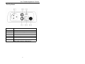
1
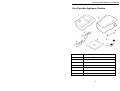
Seaward Europa Plus
Portable Appliance Checker
Instruction Manual
293A552 Rev 1.0
December 2002
© 2002 Seaward Electronic Ltd.
Issue 1.0
Limited Warranty & Limitation of Liability
SEAWARD Electronic Limited guarantees this product for a period of
1 year. The period of warranty will be effective at the day of delivery.
© Copyright 2002
All rights reserved. Nothing from this edition may be multiplied, or
made public in any form or manner, either electronically,
mechanically, by photocopying, recording, or in any manner, without
prior written consent from SEAWARD Electronic Limited. This also
applies to accompanying drawings and diagrams.
Due to a policy of continuous development SEAWARD Electronic
Limited reserves the right to alter the equipment specification and
description outlined in this publication without prior notice and no part
of this publication shall be deemed to be part of any contract for the
equipment unless specifically referred to as an inclusion within such
contract.
Table of Contents
Declaration of Conformity.......................................................... 1
Before Starting .......................................................................... 2
Safety ........................................................................................ 3
CHAPTER 1 INTRODUCING THE TESTER ................. 5
Introduction................................................................................ 5
Your Portable Appliance Checker ............................................. 6
The Top Panel................................................................. 7
The Keyboard ............................................................................ 8
The Rotary Switch ..................................................................... 9
Definitions.................................................................................. 9
CHAPTER 2 USING THE TESTER ............................. 10
Introduction.............................................................................. 10
Controls ......................................................................... 10
Display........................................................................... 10
Connecting the Tester ............................................................. 12
Set-Up Data............................................................................. 12
Beeper Setting .............................................................. 12
Substitute Leakage Setting ........................................... 12
Leakage Test Setting .................................................... 12
Performing a Test.................................................................... 12
After a Test.................................................................... 12
Abort Actions................................................................. 12
Storing Test Results ................................................................ 12
Set Date ........................................................................ 12
Appliance Number and Storing Results........................ 12
Memory Options............................................................ 12
i
Table of Contents
Send Data................................................................................ 12
Download Data Format ................................................. 12
AC Earth Continuity Tests ....................................................... 12
DC Earth Continuity Tests....................................................... 12
Insulation Tests ....................................................................... 12
Substitute Leakage Test.......................................................... 12
Powered Tests ........................................................................ 12
Differential Leakage Test ........................................................ 12
Touch Leakage Test................................................................ 12
Load Test................................................................................. 12
External Leakage Test ............................................................ 12
IEC Lead Test ......................................................................... 12
Testing 110v Appliances ......................................................... 12
CHAPTER 3 TIPS & TROUBLESHOOTING............... 12
Tester Self Tests: .................................................................... 12
Powered Tests ........................................................................ 12
Temperature monitoring .......................................................... 12
Multiple Earth connections: ..................................................... 12
Interfacing................................................................................ 12
CHAPTER 4 MAINTAINING THE TESTER................. 12
Cleaning the Tester ................................................................. 12
User Maintenance ................................................................... 12
CHAPTER 5 ACCESSORIES...................................... 12
Standard Accessories ............................................................. 12
Optional Accessories............................................................... 12
ii
Table of Contents
CHAPTER 6 SPECIFICATIONS.................................. 12
AC Earth Continuity Test......................................................... 12
DC Earth Continuity Test......................................................... 12
Insulation Test ......................................................................... 12
Substitute Leakage Test.......................................................... 12
Differential Leakage ................................................................ 12
Touch Leakage........................................................................ 12
Load Test................................................................................ 12
External Leakage .................................................................... 12
Lead Test................................................................................. 12
Mechanical .............................................................................. 12
Environmental ......................................................................... 12
APPENDIX .................................................................... 12
Test Limits ............................................................................... 12
Earth Continuity Limit .............................................................. 12
Insulation Resistance Limits.................................................... 12
Protective Conductor / Touch Current Limits .......................... 12
iii
Declaration of Conformity
Declaration of Conformity
for the
Seaward Europa Portable Appliance Checker
Manufactured by:
Seaward Electronic Ltd, Bracken Hill, South West Industrial Estate
Peterlee, County Durham, SR8 2SW, England
Millennium Statement
This product is Millennium compliant, and conforms fully to the
document BSI DISC PD2000-1.
Statement of Conformity
Based on test results using appropriate standards, the product is in
conformity with Electromagnetic Compatibility Directive 89/336/EEC
and Low Voltage Directive 73/23/EEC
Standards used:
EN 61010-1 (1993) Safety Requirements for Electrical Equipment for
Measurement, Control, and Laboratory Use
EN 50081-1 (1992) Electromagnetic Compatibility. Generic Emission
Standard: EN55022 Class B
EN 50082-1 (1992) Electromagnetic Compatibility. Generic Immunity
Standard: IEC1000-4-2, -4-3, -4-4, -4-5
The tests have been performed in a typical configuration.
This Conformity is indicated by the symbol
Européenne
1
, i.e. “Conformité
Before Starting
Before Starting
Upon receipt of your Europa PAC Plus Tester:1.
Check that all the component parts are present:• Seaward Europa PAC Plus Tester
• Earth Continuity lead
• 110v Adaptor
• PATSLite Software disc
• Computer Lead
• Instruction Manual
• Carrying Case
2.
Read the operating instructions fully before conducting any
tests.
3.
Contact Seaward Electronic if you need information on
training for Portable Appliance Testing. Courses can be
arranged at Seaward, or at customer premises.
4.
Seaward Electronic Limited can be contacted at:
Bracken Hill
South West Industrial Estate
Peterlee
Co. Durham
SR8 2SW
Tel : +44 (0)191 586 3511
Fax: +44 (0)191 586 0227
[email protected]
2
Safety
Safety
Note
Please read the following Safety Instructions before use !
Safety Precautions
The manual contains specific warning and caution statements where
they apply.
A Warning will identify the conditions and actions that pose
hazard(s) to the user.
A Caution will identify the conditions and actions that may
damage the Tester.
Symbols used within this manual and on the Tester are shown below:
Risk of electric shock
Warning of potential
hazard
Conformité Européenne
Use of the instrument in a manner not specified may impair safety.
Read the following safety information carefully before attempting to
operate the instrument.
3
Safety
Warning
Due to the potential hazards associated with any
electrical circuit it is important that the user is familiar
with the instructions covering the capabilities and
operation of this instrument. The user should ensure
that all reasonable safety precautions are followed and if
any doubt exists should seek advice before proceeding.
This product is designed for use by suitably trained
competent personnel and should be operated strictly in
accordance with the instructions supplied.
Failure to comply with these instructions may expose the user to
electrical hazard
This Tester performs a number of electrical tests which involve high
voltages and high currents. Never touch the appliance being tested,
or the test leads, whilst a test is in progress.
Always check all test leads for signs of damage prior to use. Never
use damaged or defective leads.
Always ensure the mains supply to the Tester provides an adequate
earth.
This manual contains information and warnings which must be
heeded to ensure user safety during operation. It is essential that
this manual is read fully before proceeding with any tests.
Should the Tester behave abnormally do not continue with the
testing. Disconnect immediately and contact Seaward Electronic for
servicing (see Chapter 4 - Maintaining the Tester).
4
Introduction
Chapter 1 Introducing the Tester
Introduction
The Seaward Europa Plus Portable Appliance Checker is a powerful
tool to assist in the analysis of the safety of portable electrical and
electronic equipment. A range of tests are provided, with innovative
features to aid difficult test situations, which allow testing of a wide
variety of equipment.
The Tester combines state of the art testability with the following
innovative features:• Truly portable, multi-voltage tester
• Accurate earth continuity and leakage measurement even when
multiple earth paths exist
• Tests Information Technology equipment
• Can measure Leakage through optional Clamp
• Stores up to 100 Test Results in memory
• Downloads to PATSLite and PATGuard Plus
• Connects to a printer to print results
• Fast Start-up
• Large, easy to read digital display
• Easy test selection
5
Your Portable Appliance Checker
Your Portable Appliance Checker
Item Number
Part
1
Europa Plus Portable Appliance Checker
2
Carrying case
3
Earth Continuity Lead
4
Computer Lead
5
PATSLite software disc
6
Instruction Manual
7
110v Adaptor
6
Your Portable Appliance Checker
The Top Panel
Item Number
Part
1
Mains socket
2
Main Earth Continuity/Insulation socket
3
RS232 Serial Interface
4
230V Mains Input
5
IEC Lead Socket
6
Auxiliary Earth Continuity socket, for point to
point earth continuity measurement
7
The Keyboard
The Keyboard
Item Number
Part
1
Rotary Switch
2
SELECT Button
3
CHANGE DISPLAY Button
4
Cursor Buttons
5
STORE RESULT Button
6
START / STOP Button
8
The Rotary Switch
The Rotary Switch
Definitions
Equipment Under Test The electrical / electronic apparatus
(EUT)
which is the subject of testing.
Powered Tests -
The EUT is supplied with mains voltage,
with measurements being taken of power
consumption, leakage currents etc.
Tester -
The Seaward Europa Portable Appliance
Checker
Un-powered Tests -
The EUT is the subject of electrical tests
using stimuli generated within the Tester.
The EUT is not provided with mains power.
User -
The test technician using the Tester to
perform tests on an EUT
9
Introduction
Chapter 2 Using the Tester
Introduction
Controls
A rotary switch defines the basic test (or action) to be performed, the
tests are arranged on the switch such that a clockwise rotation is
needed to perform a normal sequence of tests.
Cursor buttons ( ↑ and ↓ ) allow for adjustment of test variables,
e.g. test duration. The SELECT button is used to change the variable
to be adjusted.
The large START/STOP button is used to start a Test.
Display
Test Icons
Primary
Display
Secondary
Display
The display consists of a number of Icons to provide visual indication
of the tester status, a primary 4 digit, 7 segment display, along with a
4 digit secondary display, and a 2 digit duration time display,
Test Icons
Indicates the test selected,
10
Introduction
Earth Continuity
Insulation
Substitute Leakage
Differential Leakage
External Leakage
Touch Leakage
Load
Lead Test
Test in Progress Icon
Indicates test in progress with voltage warning.
Low Voltage
High Voltage
Applying Mains Power
Test Duration Counter
Indicates the timing of the test. This will count down, when the
counter reaches zero if the Europa is still taking a measurement the
counter will flash.
11
Connecting the Tester
Primary Display
Indicates test result
Secondary Display
Before and during a test this display Indicates test output e.g. voltage
or current specified. After a test, this display compares the test result
with standard limits.
Connecting the Tester
The Tester must be powered by a 230V supply but can test both 230v
and 110v appliances (see Testing 110v Appliances).
The supply to the tester must include an earth connection (e.g. via a
3 pin plug).
When switched on, the Tester will carry out a short self-test
procedure (approximately 4 seconds). During this test, all display
segments will be lit to allow verification of correct operation of the
display
Once the start-up procedure of the Tester has been completed, the
tester is ready for operation. The display will depend on the rotary
knob position.
Set-Up Data
There are a number of settings that enable the user to set up the
tester to perform in a particular manner. These are available by
turning the rotary knob to the Set-Up Data position.
Beeper Setting
Different beep settings can be configured. With the primary display
flashing the user can cycle through the current beep settings using
the cursor buttons. Each option is described below.
ton1 – Beep at key press
ton2 – Beep at start of test and at end of test, if test Pass beep twice
at end
12
Set-Up Data
ton3 – Beep when mains voltage applied to test socket
ton4 – Beep if test limit exceeded
To set the selected option to off or on press the SELECT button. Now
the option’s setting will flash, use the cursor buttons to chose the
preferred setting, then press the STORE RESULT to go back to the
options. At any time you can switch the rotary knob to a different
selection and the current beep options will be active.
Substitute Leakage Setting
The Substitute Leakage can be set to display the reading for different
set level increases in mains voltage. These are:
230v = 0%
244v = 6%
253v = 10%
With the primary display flashing cycle through the settings until
SubS is displayed using the cursor buttons.
To set the selected option, press the SELECT button. Now the
option’s setting will flash, use the cursor buttons to chose the
preferred setting, then press the STORE RESULT to go back to the
options. At any time you can switch the rotary knob to a different
selection and the current option will be active.
Leakage Test Setting
If a Leakage test exceeds the display range, the test can be stopped
or allowed to carry on.
With the primary display flashing cycle through the settings until SEt1
is displayed using the cursor buttons.
To set this option to off or on press the SELECT button. Now the
option’s setting will flash, use the cursor buttons to chose the
preferred setting, then press the STORE RESULT to go back to the
options. At any time you can switch the rotary knob to a different
selection and the current options will be active.
13
Performing a Test
Performing a Test
All tests are performed in a similar way - Rotate the switch to the
appropriate test. For un-powered tests the test duration will be
flashing in the top left corner. Use the cursor buttons to change the
test time if required. Press the SELECT button to set other options
for the test.
For most tests a test limit can also be set. Use the cursor buttons to
select pre-defined limits or the user adjustable limit indicated by a
plus (+) to the left of the limit. For details on test settings refer to the
actual tests in this Instruction Manual.
When satisfied with the test conditions, press the START/STOP
button to start the test
After a Test
After the Tester completes the selected test, the measured value
continues to be displayed until a button is pressed, or a different test
is selected.
The Secondary display provides a comparison with
standard test values.
Abort Actions
A test can aborted at any time by rotating the rotary switch. Note
however that due to the functionality of the Load, Leakage and Touch
Leakage tests the rotary knob must be rotated beyond these tests
before they will be aborted.
Storing Test Results
The Europa PAC plus is able to store test results. To store results
perform the required test and press STORE RESULTS.
Please note that timed tests can only be stored at the end of the test
while tests which are continuous can be stored during and at the end
of the result.
Set Date
As the date is required to be stored with each test result the first time
you store a result the tester prompts you to enter the dat.
14
Storing Test Results
The first time the STORE RESULT button is pressed after switch on
after performing a test the user will be prompted to enter the date.
The primary display will flash dAt for approximately 2s then display
the currently set day / month e.g. 12.07 for 12 July. The secondary
display will show the currently set year. The leading day digit will be
flashing, indicating that it can be changed. Use the cursor buttons to
change the value. Press the SELECT button to allow the second day
digit to be changed, indicated by the digit flashing. Use the cursor
buttons to change its value. Press the SELECT button to allow the
month to be changed. Proceed to change the month in the same way
as the day. After the month is changed, the year can be changed in
the same manner.
At any time (when the entire date is correct) pressing the STORE
RESULT button will cause the tester to check the date is valid and if
correct will store it to memory. Invalid dates will not be stored.
All subsequent result stores will not ask for the date until the tester is
reset.
Press STORE RESULT to store the displayed date.
At any time during the date entry, pressing the CHANGE DISPLAY
button or rotary switch action cancel any changes and leave the date
unchanged in memory.
Appliance Number and Storing Results
After the date has been stored or has been set on a previous store,
pressing the STORE RESULTS button will cause the primary display
to flash STOR for about 2s then both primary and secondary displays
will display four digits each (eight total) with the lead digit flashing.
Use the cursor buttons to change the value of the digit. Pressing the
SELECT button will cause the next digit in turn to flash indicating that
its value can be changed using the cursor buttons. Use the SELECT
button to select each digit in turn changing the value if appropriate
with the cursor buttons until the correct appliance number is
displayed.
Press the STORE RESULT button to store the displayed appliance
number. The tester will display STOR on the primary display with the
secondary display alternating between ‘----‘ and a memory location
for approximately 2s. Confirmation that the result has been stored is
signaled by two short beeps.
15
Storing Test Results
If the memory is full when attempting to store a result the primary
display will show STOR with the secondary display flashing Full.
Memory Options
There are three options available:
• Recall result
• Delete last result
• Delete all data
• Memory available
Move the rotary switch to Data Look Up, use the cursor buttons to
select a memory option.
Recall Result
Use the cursor buttons to select rCL. Press the SELECT button to
select this option. The two digits in the top right hand corner indicate
appliance location. The primary display shows the measured value.
The secondary display shows the test limit. The type of test is
indicated by the test icon.
The cursor buttons are use to move through the memory locations.
On initial entry into recall result the last saved memory location is
displayed.
If an attempt is made to recall a result outside of the saved memory
range a message is displayed. Attempting to recall below the first
saved result will cause bot to be displayed. Attempting to recall above
the last saved result will cause the toP to be displayed.
Delete Last Result
Use the cursor buttons to select CLr. Press the SELECT button to
select this option. The two digits in the top right hand corner indicate
memory location. The primary display shows the measured value.
The secondary display shows the test limit. The type of test is
indicated by the test icon. Only the last result in memory can be
deleted.
16
Send Data
To delete the result press the START / STOP button. While erasing
the result secondary display will flash ‘----‘. After deleting the result
the memory location number will be decremented by one.
Delete All Data
Use the cursor buttons to select Clr on the primary display with ALL
on the secondary display. Press the SELECT button to select this
option.
Press the START / STOP button to delete all data. Both primary and
secondary displays will flash, awaiting confirmation. To confirm that
you wish to delete all data press the START / STOP button again.
Memory Available
Use the cursor buttons to select STOR. Press the SELECT button to
select this option.
The two digits in the top right hand corner indicate memory location
last used. The secondary display indicates the percentage of free
memory available.
Send Data
To print the test results stored in memory or to download them to an
appropriate PC program, select Send Data with the rotary switch.
Note
Only the PATSLite program (supplied with the tester) and the
PATGuard Plus program are capable of processing test results from
the Europa PAC Plus.
The primary display will alternate between Send and PrSt indicating
press START / STOP button to commence sending data. With the
printer connected and on-line or with the program awaiting test
results, press the START / STOP button.
While sending data the primary display will show Send with the
secondary display showing ‘----‘. When complete the primary display
will show End.
17
AC Earth Continuity Tests
Note
All of the current contents of memory are sent. It is not possible to be
selective.
Download Data Format
The data format will be as follows for Appliance Tests:
TEST NUMBER
DATE
APP NO
EARTH (10A)
INS (250V)
SUB LKGE
DIFF LKGE
TOUCH LKGE
EXT LKGE
LOAD
VOLTS
CURRENT
002
18/05/02
12345678
0.01Ohm P
8.00MOhm P
0.24mA P
0.30mA P
0.30mA P
0.28mA P
3.68kVA
230V
5.65A
The data format will be as follows for Lead Tests:
TEST NUMBER
001
DATE
19/05/02
APP NO
12345679
EARTH (100mA)
0.03Ohm P
INS (500V)
>99.99MOhm P
POLARITY
PASSED
The last test block is indicated by:
END OF DATA
AC Earth Continuity Tests
18
AC Earth Continuity Tests
Switch Position ------------
Earth Continuity A~
Test Icon Displayed --Class 1 (earthed) appliances
Plug the EUT into the tester outlet socket, connect the Earth
Continuity lead from its socket to the appliance metal part.
Class 2 (unearthed) appliances
This test cannot be performed since no earth connection is present in
the appliance plug.
Test Description
This test is to ensure that the connection between the earth pin in the
mains plug of the appliance and the metal casing of the appliance is
satisfactory and of sufficiently low resistance.
The 10A test current is applied between the earth pin of the mains
supply plug and the earth continuity test lead clip.
A high current is normally used to stress the connection under fault
conditions. The length of the test should be limited to prevent
damage due to overheating.
User Selectable Settings
Each press of the SELECT button will allow you to cycle through the
user selectable settings; test duration and test limit. The currently
selected setting will be flashing.
Test Duration
With the test duration flashing, use the cursor keys to step through
the test duration settings. A test duration can be set from 2s to 10s in
1s steps.
19
DC Earth Continuity Tests
Press the SELECT button to change to another setting or press the
START/STOP button to perform the test if the other settings are
acceptable.
Test Limit
With the secondary display flashing and indicating resistance (Ω
displayed), use the cursor keys to step through the test limits
available and stop with the appropriate limit displayed.
A special limit indicated by a plus sign (+) to the left of the limit, is a
user adjustable limit.
To set your own limit, with this user adjustable limit flashing press
both cursor keys together. The limit as a whole will stop flashing with
the most significant digit flashing. Use the cursor buttons to set a
value for the flashing digit. Press the SELECT button to enable the
next digit in turn to flash. Use the cursor buttons to set a value for this
flashing digit. Then press the SELECT button to move to the next
digit. Repeat these actions until all digits are set to your chosen
value. Press the STORE RESULT button to set the limit.
Press the SELECT button to change to another setting or press the
START/STOP button to perform the test if the other settings are
acceptable.
DC Earth Continuity Tests
Switch Position ----------Earth Continuity
Test Icon Displayed ---
Class 1 (earthed) appliances
Plug the EUT into the tester outlet socket, connect the Earth
Continuity lead from its socket to the appliance metal part.
20
DC Earth Continuity Tests
Class 2 (unearthed) appliances
This test cannot be performed since no earth connection is present in
the appliance plug.
Test Description
This test is to ensure that the connection between the earth pin in the
mains plug of the appliance and the metal casing of the appliance is
satisfactory and of sufficiently low resistance.
The test current is applied between the earth pin of the mains supply
plug and the earth continuity test lead clip.
User Selectable Settings
Each press of the SELECT button will allow you to cycle through the
user selectable settings; test duration and test limit. The currently
selected setting will be flashing.
Test Duration
With the test duration flashing, use the cursor keys to step through
the test duration settings. A test duration can be set from 2s to 60s in
1s steps or a continuous measurement indicated by two dashes (--).
When a fixed test duration is set, the time will be divided into two
equal periods. During the first period a test current of +200mA will be
applied. During the second period a test current of –200mA will be
applied.
If a continuous test duration is set then, the first press of the
START/STOP button will generate a +200mA test current
continuously. Pressing the START/STOP button again will stop the
test. Pressing the START/STOP button a third time will generate a –
200mA test current.
Press the SELECT button to change to another setting or press the
START/STOP button to perform the test if the other settings are
acceptable.
Test Limit
21
Insulation Tests
With the secondary display flashing and indicating resistance (Ω
displayed), use the cursor keys to step through the test limits
available and stop with the appropriate limit displayed.
A special limit indicated by a plus sign (+) to the left of the limit, is a
user adjustable limit.
To set your own limit, with this user adjustable limit flashing press
both cursor keys together. The limit as a whole will stop flashing with
the most significant digit flashing. Use the cursor buttons to set a
value for the flashing digit. Press the SELECT button to enable the
next digit in turn to flash. Use the cursor buttons to set a value for this
flashing digit. Then press the SELECT button to move to the next
digit. Repeat these actions until all digits are set to your chosen
value. Press the STORE RESULT button to set the limit.
Press the SELECT button to change to another setting or press the
START/STOP button to perform the test if the other settings are
acceptable.
Insulation Tests
Switch Positions ------------
250V / 500V
Insulation
Test Icon Displayed ---
Warning
250 or 500V d.c. test
voltage
Class 1 (earthed) appliances
Plug the EUT into the tester outlet socket
Class 2 (unearthed) appliances
Plug the EUT into the tester outlet socket, connect the Earth
Continuity lead from the Main socket to the appliance metal part.
22
Insulation Tests
Test Description
This test is used to verify that adequate insulation exists between the
mains supply pins and earth.
During the insulation test, a 250V or 500V DC voltage is applied
between the earth pin and both the live and neutral pins of the
appliance mains supply plug. The Tester displays the resistance
measured and allows the user to confirm sufficient insulation exists.
For Class 2 appliances, the Earth Continuity Test is used for an earth
return lead.
For appliances which incorporate over-voltage protection, and hence
produce a false failure condition when 500v insulation tests are used,
a 250V test voltage is provided to allow a reading to be taken without
the protection devices generating a false failure.
User Selectable Settings
Each press of the SELECT button will allow you to cycle through the
user selectable settings; test duration, test voltage and test limit. The
currently selected setting will be flashing.
Test Duration
With the test duration flashing, use the cursor keys to step through
the test duration settings. A test duration can be set from 2s to 60s in
1s steps or a continuous measurement indicated by two dashes (--).
Press the SELECT button to change to another setting or press the
START/STOP button to perform the test if the other settings are
acceptable.
Test Voltage
With the secondary display flashing and indicating voltage (v
displayed), use the cursor keys to step through the test voltage
options. A 250V or 500V test voltage can be set.
Test Limit
With the secondary display flashing and indicating resistance (MΩ
displayed), use the cursor keys to step through the test limits
available and stop with the appropriate limit displayed.
23
Substitute Leakage Test
A special limit indicated by a plus sign (+) to the left of the limit, is a
user adjustable limit.
To set your own limit, with this user adjustable limit flashing press
both cursor keys together. The limit as a whole will stop flashing with
the most significant digit flashing. Use the cursor buttons to set a
value for the flashing digit. Press the SELECT button to enable the
next digit in turn to flash. Use the cursor buttons to set a value for this
flashing digit. Then press the SELECT button to move to the next
digit. Repeat these actions until all digits are set to your chosen
value. Press the STORE RESULT button to set the limit.
Press the SELECT button to change to another setting or press the
START/STOP button to perform the test if the other settings are
acceptable.
Substitute Leakage Test
Substitute Leakage
Switch Position -----------Test Icon Displayed ---
Class 1 (earthed) appliances
Plug the EUT into the tester outlet socket.
Class 2 (unearthed) appliances
Plug the EUT into tester outlet socket, connect the Earth Continuity
lead from its socket to the appliance metal part.
Test Description
The substitute leakage test applies a nominal voltage of 40V AC RMS
to the appliance and is applied between the earth pin and both the
live and neutral pins of the supply plug. For Class II appliances,
connect the Earth Continuity test clip to the appliance as a substitute
for the Earth.
24
Substitute Leakage Test
The Tester measures the current that flows and scales the result to
display a guide to the current that would flow if the test voltage had
been the nominal mains supply voltage.
Please note that values for Substitute Leakage may differ
substantially from that of conventional Earth Leakage tests because
of the way that the test is performed (e.g. it will be affected by the
presence of Neutral-to-Earth suppression devices).
This test can prove useful in situations where conventional Insulation
tests are unacceptable.
User Selectable Settings
Each press of the SELECT button will allow you to cycle through the
user selectable settings; test duration and test limit. The currently
selected setting will be flashing.
Test Duration
With the test duration flashing, use the cursor keys to step through
the test duration settings. A test duration can be set from 2s to 60s in
1s steps or a continuous measurement indicated by two dashes (--).
Press the SELECT button to change to another setting or press the
START/STOP button to perform the test if the other settings are
acceptable.
Test Limit
With the secondary display flashing and indicating current (mA
displayed), use the cursor keys to step through the test limits
available and stop with the appropriate limit displayed.
A special limit indicated by a plus sign (+) to the left of the limit, is a
user adjustable limit.
To set your own limit, with this user adjustable limit flashing press
both cursor keys together. The limit as a whole will stop flashing with
the most significant digit flashing. Use the cursor buttons to set a
value for the flashing digit. Press the SELECT button to enable the
25
Powered Tests
next digit in turn to flash. Use the cursor buttons to set a value for this
flashing digit. Then press the SELECT button to move to the next
digit. Repeat these actions until all digits are set to your chosen
value. Press the STORE RESULT button to set the limit.
Press the SELECT button to change to another setting or press the
START/STOP button to perform the test if the other settings are
acceptable.
Powered Tests
Warning
Mains voltage applied to appliance
The following powered tests differ from the previous tests in that they
apply mains supply voltage to the appliance to perform their
functions:• Differential Leakage
• Touch Leakage
• Load
Note
These tests are not available when using the 110v adaptor.
The Tester performs an initial low voltage test to establish that the
appliance can be safely powered.
When the rotary switch is rotated through the different power tests
the power supply is not interrupted but the test counter is reset. This
allows the user to obtain results from all three tests without having to
interrupt the power. To abort a power test rotate the knob beyond the
power tests.
Warning
It is important that the user verifies that an appliance
with moving parts (e.g. an electric drill) is safely
mounted to allow movement without causing damage to
equipment or personnel.
26
Differential Leakage Test
If the potential load current is too high, a warning message appears,
allowing the user to continue. This message will be displayed if a
Live to Neutral short exists, and if tests are continued the tester’s
fuses will blow.
If the potential load current is low, a warning message appears to
allow the user to check that the appliance is switched on, and all
fuses are intact.
The Tester also performs an internal safety test to verify that internal
relays are properly set before applying full mains supply to the
appliance.
Differential Leakage Test
Switch Position ------------
Differential Leakage
Test Icon Displayed --Warning
Mains voltage applied to appliance
All Appliances
Plug EUT into tester outlet socket
Test Description
The Differential Leakage Test shows the current being lost through
Leakage as the difference in the currents flowing in the Live and the
Neutral conductors. This difference is the total leakage current from
the appliance, and is generally equivalent to the current flow through
the earth lead of the appliance. The test result is displayed in
milliamps (mA).
27
Touch Leakage Test
This differential method of determining leakage will show the full
leakage of an appliance in-situ, so if the appliance has an extra earth
point, e.g. a water pipe, then the Tester will show the full and true
appliance leakage current.
Test Duration
The test is continuous and is stopped by either pressing the
START/STOP button or by switching to an un-powered test. In both
cases the test will be stopped and the power to the appliance
removed. Switching to another powered test will stop the previous
test and start the new test without interrupting power to the appliance.
User Selectable Settings
Only the test limit can be set by the user for this test.
Test Limit
With the secondary display flashing and indicating current (mA
displayed), use the cursor keys to step through the test limits
available and stop with the appropriate limit displayed.
A special limit indicated by a plus sign (+) to the left of the limit, is a
user adjustable limit.
To set your own limit, with this user adjustable limit flashing press
both cursor keys together. The limit as a whole will stop flashing with
the most significant digit flashing. Use the cursor buttons to set a
value for the flashing digit. Press the SELECT button to enable the
next digit in turn to flash. Use the cursor buttons to set a value for this
flashing digit. Then press the SELECT button to move to the next
digit. Repeat these actions until all digits are set to your chosen
value. Press the STORE RESULT button to set the limit.
Press the SELECT button to change to another setting or press the
START/STOP button to perform the test if the other settings are
acceptable.
Touch Leakage Test
Switch Position ------------
Touch Leakage
Test Icon Displayed --28
Touch Leakage Test
Warning
Mains voltage applied to appliance
All Appliances
Plug EUT into tester outlet socket, use Earth Continuity lead from
Main socket to appliance metal part.
Test Description
The Touch Leakage Test displays the leakage current that would flow
if the appliance was touched by a person. The Tester detects any
current flowing in the Earth Continuity Lead (attached to an
appropriate point on the appliance) and indicates the potential
leakage through a metal panel. The Tester displays the result in
milliamps (mA).
Test Duration
The test is continuous and is stopped by either pressing the
START/STOP button or by switching to an un-powered test. In both
cases the test will be stopped and the power to the appliance
removed. Switching to another powered test will stop the previous
test and start the new test without interrupting power to the appliance.
User Selectable Settings
Only the test limit can be set by the user for this test.
Test Limit
With the secondary display flashing and indicating current (mA
displayed), use the cursor keys to step through the test limits
available and stop with the appropriate limit displayed.
A special limit indicated by a plus sign (+) to the left of the limit, is a
user adjustable limit.
29
Load Test
To set your own limit, with this user adjustable limit flashing press
both cursor keys together. The limit as a whole will stop flashing with
the most significant digit flashing. Use the cursor buttons to set a
value for the flashing digit. Press the SELECT button to enable the
next digit in turn to flash. Use the cursor buttons to set a value for this
flashing digit. Then press the SELECT button to move to the next
digit. Repeat these actions until all digits are set to your chosen
value. Press the STORE RESULT button to set the limit.
Press the SELECT button to change to another setting or press the
START/STOP button to perform the test if the other settings are
acceptable.
Load Test
Switch Position ------------
Load
Test Icon Displayed ---
Warning
Mains voltage applied to appliance
All Appliances
Plug the EUT into the tester outlet socket.
Test Description
The Load test supplies the equipment under test (the appliance),
connected to 230V test socket, with the rated voltage of that socket.
The tester displays the mains voltage (V) applied to the Appliance on
the secondary display. The current (A) drawn by the Appliance during
the test is displayed on the primary display. Pressing the CHANGE
DISPLAY button will cause the primary display to show power
consumption in KVA. Repeated pressing of the CHANGE DISPLAY
button will cycle the primary display between power and current.
30
External Leakage Test
Test Duration
The test is continuous and is stopped by either pressing the
START/STOP button or by switching to an un-powered test. In both
cases the test will be stopped and the power to the appliance
removed. Switching to another powered test will stop the previous
test and start the new test without interrupting power to the appliance.
User Selectable Settings
There are no user selectable settings.
External Leakage Test
Switch Position ------------External Leakage (Clamp)
Test Icon Displayed ---
Warning
Mains voltage applied to appliance
Note
This test requires the use of a current clamp, which is an optional
accessory (see Chapter 5 Accessories).
All Appliances
Plug the current clamp into the appropriate socket. Open the clamp
jaws and clamp around the cable you wish to measure current flow
through. Power is applied to the EUT at the mains socket.
Test Description
The tester will display the current detected by the external clamp. If
this is around a protective conductor, earth leakage will be displayed.
If the clamp is around the phase and neutral conductors then
31
IEC Lead Test
differential leakage will be displayed. DO NOT connect the clamp
around only the phase or neutral conductors.
Test Duration
The test is continuous and is stopped by either pressing the
START/STOP button or by switching to another test. In both cases
the test will be stopped.
User Selectable Settings
Only the test limit can be set by the user for this test.
Test Limit
With the secondary display flashing and indicating current (mA
displayed), use the cursor keys to step through the test limits
available and stop with the appropriate limit displayed.
A special limit indicated by a plus sign (+) to the left of the limit, is a
user adjustable limit.
To set your own limit, with this user adjustable limit flashing press
both cursor keys together. The limit as a whole will stop flashing with
the most significant digit flashing. Use the cursor buttons to set a
value for the flashing digit. Press the SELECT button to enable the
next digit in turn to flash. Use the cursor buttons to set a value for this
flashing digit. Then press the SELECT button to move to the next
digit. Repeat these actions until all digits are set to your chosen
value. Press the STORE RESULT button to set the limit.
Press the SELECT button to change to another setting or press the
START/STOP button to perform the test if the other settings are
acceptable.
IEC Lead Test
Switch Position ------------ Lead Test
Test Icon Displayed ---
32
IEC Lead Test
For IEC Leads
Plug the lead into the tester outlet socket and plug the IEC end into
the tester’s IEC socket.
For Extension Leads
Plug the lead into the tester outlet socket and use a short IEC lead to
connect from the tester’s IEC socket to the extension lead outlet
socket.
Test Description
The IEC test performs in sequence an earth continuity, insulation and
polarity check on the Live and Neutral conductors and confirms that
there are no breaks or cross wiring in these conductors.
User Selectable Settings
Each press of the SELECT button will allow you to switch between
user selectable test limit for Earth Continuity and Insulation. The
currently selected setting for the selected test will be flashing.
Note
To determine which test limit is currently displayed, observe the unit
of measurement symbol. For Earth Continuity Ω is displayed. For
Insulation MΩ is displayed.
Test Limits
With the secondary display flashing use the cursor keys to step
through the test limits available and stop with the appropriate limit
displayed.
A special limit indicated by a plus sign (+) to the left of the limit, is a
user adjustable limit.
Press SELECT to swap between the Earth Bond and Insulation
pass/fail limits.
33
Testing 110v Appliances
To set your own limit, with this user adjustable limit flashing press
both cursor keys together. The limit as a whole will stop flashing with
the most significant digit flashing. Use the cursor buttons to set a
value for the flashing digit. Press the SELECT button to enable the
next digit in turn to flash. Use the cursor buttons to set a value for this
flashing digit. Then press the SELECT button to move to the next
digit. Repeat these actions until all digits are set to your chosen
value. Press the STORE RESULT button to set the limit.
Press the SELECT button to change to another setting or press the
START/STOP button to perform the test if the other settings are
acceptable.
Test Sequence
The first test is an Earth Continuity test at 200mA. This is indicated by
the secondary display showing PE Ω.
The test is divided into two 2s tests. During the first period a test
current of +200mA will be applied. During the second period a test
current of –200mA will be applied.
The second test is an Insulation test at 500v d.c. This is indicated by
the secondary display showing LnPE MΩ.
The third test checks the lead wiring is correct. This test checks for
open circuit or shorted wires as well as crossed polarity between
Phase and Neutral. The result of this test is displayed as a Pass or
Fail.
By pressing the CHANGE DISPLAY button at the end of the test and
using the cursor buttons it is possible to cycle through the test results
for the Lead Test.
Testing 110v Appliances
The 110v adaptor lead is used to connect 110v appliances to the
tester’s outlet socket. Only Earth Continuity, Insulation and Substitute
Leakage measurements can be made.
The adaptor lead is wired to prevent power tests being performed,
since this would supply full mains voltage (230v) to the EUT.
34
Tester Self Tests:
Chapter 3 Tips & Troubleshooting
Tester Self Tests:
When the tester is powered on and prior to certain tests, a number of
messages can appear as the tester performs safety tests on itself
and the mains power supply. If a fault is identified, Err appears on
the primary display and the error number is shown on the secondary
display. If any of the self tests fail, then one of the following displays
will be seen.
Err 01 with flashing cross
No Earth to tester
Have the mains power socket that is supplying power to the tester
checked. If the power socket checks out Ok then the tester may have
an internal fault and should be returned to your Service Agent
Err 02 with flashing cross
Incoming mains Live voltage on Neutral.
Have the mains power socket that is supplying power to the tester
checked. If the power socket checks out Ok then the tester may have
an internal fault and should be returned to your Service Agent
35
Powered Tests
Err 03 with flashing cross
Internal relay fault
Return to your Service Agent if problem persists.
Err 04 with flashing cross
Internal relay fault
Return to your Service Agent if problem persists.
Err 05 with flashing cross
Internal relay fault
Return to your Service Agent if problem persists.
Err 06 with flashing cross
Internal relay fault
Return to your Service Agent if problem persists.
Err 07 with flashing cross
Memory corruption.
Return to your Service Agent.
Powered Tests
The Tester performs a number of checks prior to and during powered
tests. The following primary display messages can occur.
Lo Po
Low power caused by load less than 60w. The user can override this
message if low load is expected by pressing the START/STOP
button.
Hi Cu
High current is expected to be drawn by the EUT. This message
appears if the current is greater than 16A. The user can override this
message, provided the current is not expected to exceed 50A, if it is
caused by a high start up current by pressing the START/STOP
button.
36
Temperature monitoring
Temperature monitoring
The tester is provided with internal temperature monitors to ensure
sensitive components are not overheated. High rates of testing may
cause this situation, especially with long Earth Continuity tests.
Setting Earth Continuity test times to 2 secs will increase operating
time. If the message Hot appears on the primary display, leave the
tester to cool down. Once the temperature is below the trip level the
display will revert to normal for the rotary switch position selected.
Multiple Earth connections:
In general, multiple earth connections to an EUT (e.g. water pipe
connections to a water heater) can cause difficulties in measurement.
This has previously needed the additional earth connections to be
isolated.
The Europa PAC Plus tester is capable of testing earth connections
in the presence of additional earth paths. The Leakage measurement
will also be correct due to the differential leakage current, rather than
the earth lead current. Measurements are thus assured without
special precautions.
37
Interfacing
Interfacing
The Tester provides a single 9 way connector for a serial interface to
a printer:The Connector pin outs for Serial port are shown below:-
Serial Port
The serial port uses a standard 9-way D-type connector
Pin
Description
1.
2.
3.
4.
5.
6.
7.
8.
9.
N.C.
RX
TX
DTR
0V
N.C.
0V
N.C.
+5V
Baud Rate:
9600
Start Bits:
2
Data Bits
8
Stop Bits:
1
Parity:
None
38
Cleaning the Tester
Chapter 4 Maintaining the Tester
Cleaning the Tester
The Tester case can be cleaned with a damp cloth, with if necessary,
a small amount of mild detergent. Prevent excessive moisture
around the socket panel or in the lead storage area.
Do not allow liquid inside the Tester, or near the sockets. Do not use
abrasives, solvents, or alcohol.
If any liquid is spilt into the Tester case, the Tester should be returned
for repair, stating the cause of the defect.
User Maintenance
The Tester is a rugged quality instrument. However, care should
always be taken when using, transporting and storing this type of
equipment. Failure to treat the product with care will reduce both the
life of the instrument and its reliability.
If the Tester is subject to condensation, allow the Tester to
completely dry before use.
• Always check the Tester and all test leads for signs of damage
and wear before use.
• Do not open the Tester under any circumstances.
• Keep the instrument clean and dry.
• Avoid testing in conditions of high electrostatic or electromagnetic
fields.
• Maintenance should only be performed by authorised personnel.
• There are no user replaceable parts in the Tester.
• The unit should be regularly calibrated (at least annually).
• For repair or calibration return the instrument to:-
39
User Maintenance
Seaward Electronic Limited.
Bracken Hill
South West Industrial Estate
Peterlee
Co. Durham
SR8 2SW
Tel : +44 (0)191 586 3511
Fax: +44 (0)191 586 0227
[email protected]
40
Standard Accessories
Chapter 5 Accessories
A series of standard and optional accessories are available for the
Seaward Europa PAC Plus Tester. The standard accessories are
supplied with the Tester.
Standard Accessories
Accessory
Part Number
Earth Continuity Test Lead
249A908
PATSLite software disc
303A912
Computer Lead
194A919
230V / 115V Adaptor
270A076
Carry Case
270A950
Instruction Manual
293A552
Optional Accessories
Accessory
Part Number
Calibration Checkbox
283A951
Thermal Printer
283A954
Thermal Paper Rolls (5)
283A964
Serial Printer Lead
283A955
PATGuard Plus software
296A910
Pass Labels (500)
91B038
41
AC Earth Continuity Test
Chapter 6 Specifications
AC Earth Continuity Test
Test Voltage *.. ............................................6V rms nominal (no load)
Test Current *.... ..................................................... 10A (into s/c load)
Range............................................................................. 0mΩ - 19.99Ω
Resolution. ................................................................................. .0.01Ω
Accuracy..................+/- 5% of reading, +/- 2 digits (0.05 - 5.00 ohms)
Pass Levels. ........................................................... 0.1Ω, User defined
Misc.............................................. ..4-wire measurement, floating earth
DC Earth Continuity Test
Test Voltage *. ...............................................4V dc nominal (no load)
Test Current * ..................................... +200mA, -200mA (into s/c load)
Range ......................................................................... .00mΩ - 19.99Ω
Resolution. ................................................................................ ..0.01Ω
Accuracy..................+/- 5% of reading, +/- 2 digits (0.05 - 5.00 ohms)
Pass Levels. ............................................................0.1Ω, User defined
Misc............................................... .4-wire measurement, floating earth
Insulation Test
Test Voltage * .............. 500V d.c. or 250V d.c. nominal (0.5MΩ load)
Short Circuit Current ............................................ 2mA d.c. maximum
Range............................................................................ 00kΩ - 100 MΩ
Resolution .............................................................0.01 MΩ (<100 MΩ)
Accuracy...................... .+/- 5% of reading, +/- 2 digits (100kΩ - 5MΩ)
Pass Levels….. ..….0.25MΩ, 0.50MΩ, 1.0MΩ, 2.0MΩ, User defined
42
Substitute Leakage Test
Substitute Leakage Test
Test Voltage * ................................................................... 40V a.c. o/c
Display Range .......................................................... 0.2 - 20.0 mA a.c.
Resolution. ................................................................................0.01mA
Accuracy...................... +/- 10% of reading, +/- 2 digits (1.00 - 20mA)
Pass Levels. ....... 0.25mA, 0.5mA, 3.5mA, 7mA, 15mA, User defined
Differential Leakage
Range...........................................................................0.0mA - 10.0mA
Resolution.. ...............................................................................0.01mA
Accuracy.......................... +/- 5% of reading, +/- 4 digits (0.2 – 20mA)
Pass Levels ........... 0.25mA, 0.25mA, 0.75mA, 3.5mA, User defined
Touch Leakage
Range.......................................................................... ..0.0mA – 3.5mA
Resolution. ................................................................................0.01mA
Accuracy......................... +/- 5% of reading, +/- 4 digits (0.1 – 3.5mA)
Pass Levels. .......................... 0.25mA, 0.75mA, 3.5mA, User defined
Load Test
Socket .............................................................................230V BS 1363
Measured Voltage .................................... 195 - 300V (Indication only)
Measured Current ................................... 0.50 – 16A (Indication only)
Measured Load .............................................0 - 4kVA (Indication only)
External Leakage
Range....................................................................... .0.0mA – 19.99mA
Resolution.. ...............................................................................0.01mA
43
Lead Test
Accuracy.........................................................................Indication only
Pass Levels ...................................................................... User defined
Lead Test
Earth Continuity
Test Voltage *. ...............................................4V dc nominal (no load)
Test Current * ..................................... +200mA, -200mA (into s/c load)
Range ......................................................................... .00mΩ - 19.99Ω
Resolution. ................................................................................ ..0.01Ω
Accuracy..................+/- 5% of reading, +/- 2 digits (0.05 - 5.00 ohms)
Pass Levels. ............................................................0.1Ω, User defined
Insulation
Test Voltage * .............. 500V d.c. or 250V d.c. nominal (0.5MΩ load)
Short Circuit Current ............................................ 2mA d.c. maximum
Range............................................................................ 00kΩ - 100 MΩ
Resolution .............................................................0.01 MΩ (<100 MΩ)
Accuracy...................... .+/- 5% of reading, +/- 2 digits (100kΩ - 5MΩ)
Pass Levels….. ..….0.25MΩ, 0.50MΩ, 1.0MΩ, 2.0MΩ, User defined
Power Conductor Continuity
Test .......................................................................................... 40V d.c
Detects............................................................... PASS, FAIL indication
* - Test stimulus based on mains supply of 230V, varies with supply
voltage.
44
Mechanical
Mechanical
Size............................................................ 450mm x 410mm x 155mm
Weight........................................................................................... 3.5kg
Environmental
Operating ............................................ . 0ºC to 40ºC (non condensing)
Storage .............................................. -10ºC to 50ºC (non condensing)
Maximum R.H ................................................................................90%
Supply Rating................................................ .230V +/- 10%, 50/60Hz
Max Output Current .......................................................................16A
45
Test Limits
Appendix
Test Limits
The following test values are recommended by the Institute of
Electrical Engineers as suitable limits for in-service testing in most
applications. Note that these are for guidance only, test engineers
must use their knowledge and common sense in each practical
application.
Earth Continuity Limit
The IEE ‘Code of Practice for In –Service Inspection and Testing of
Electrical Equipment’ defines the pass limit for earth continuity as:
< 0.1 + R*
* where R is the resistance of the protective conductor of the supply
cord –cables of 2 metre or less should be less than 0.1Ω
Note that actual readings depend on good connection to the Earth
Continuity Clip and to the Earth Pin.
Insulation Resistance Limits
Appliance Class
Insulation Resistance
Class I heating equipment with a
rating ≥ 3 kW
0.3MΩ
All other Class I equipment
1.0MΩ
Class II equipment
2.0MΩ
Class III equipment
0.25MΩ
46
Protective Conductor / Touch Current Limits
Protective Conductor / Touch Current Limits
Appliance Class
Maximum Current
Portable or hand held Class I
equipment
0.75mA
Class I heating appliances
0.75mA or 0.75mA per kW,
whichever is the greater with a
maximum of 5mA
Other Class I equipment
3.5mA
Class II equipment
0.25mA
Class III equipment
0.5mA
Copies of the IEE ‘Code of Practice for In-Service Inspection and
Testing of Electrical Equipment ‘ may be obtained from:
The Institution of Electrical Engineers
P.O. Box 96
Stevenage,
Herts SG1 2SD
ISBN 0 85296 776 4
47