1
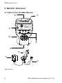
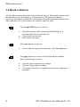
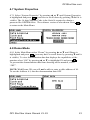
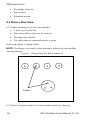
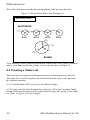
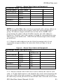
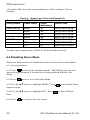
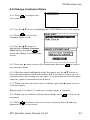
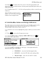
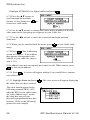
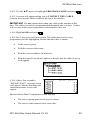
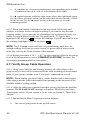
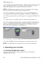
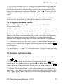
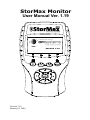
StorMax Monitor User Manual Ver. 1.19 Version 1.19 Version 1.19 January 10, 2006 OPISystems Inc. Table of Contents 1. INTRODUCTION............................................................................... 4 2. LIST OF FEATURES ......................................................................... 5 3. MONITOR OVERVIEW.................................................................... 6 3.1 PARTS OF THE STORMAX MONITOR .................................................. 6 3.2 MONITOR BUTTONS ......................................................................... 8 4. BASIC OPERATION ........................................................................10 4.1 UNITS .............................................................................................10 4.2 AUTO POWER..................................................................................10 4.3 DATE / TIME ...................................................................................11 4.4 DATA LOGGING ..............................................................................11 4.5 CONTRAST ......................................................................................12 4.6 FONT SIZE ......................................................................................12 4.7 SYSTEM PROPERTIES .......................................................................13 4.8 DEMO MODE...................................................................................13 5. WORKING WITH THE DEMO MODE ..........................................14 5.1 EXPLORING YOUR SITE ON THE MONITOR ........................................14 5.2 LATEST TEMPERATURES ..................................................................14 5.3 HISTORIC TEMPERATURES ...............................................................15 5.4 2D GRAPH ......................................................................................16 5.5 READING A TEMPERATURE CABLE ...................................................17 6. SETTING UP YOUR SITE ...............................................................17 6.1 REQUIRED MATERIALS ....................................................................17 6.2 DRAW A PLAN VIEW .......................................................................18 6.3 CREATING A CABLE LIST .................................................................20 6.4 DISABLING DEMO MODE .................................................................22 6.5 CHANGE CUSTOMER NAME .............................................................23 6.6 ADD GROUPS ..................................................................................24 6.7 ADD STORMAX CABLES AND ASSIGN ADDRESSES ...........................25 6.8 ADDING OPI-ONE OR THERMOCOUPLE CABLES ...............................27 6.9 ORGANIZE CABLES .........................................................................28 6.10 PROGRAMMING CABLES ................................................................28 6.11 VERIFY GROUP CABLE OPERATION ................................................30 6.12 INSTALL CABLES AND INTERCONNECTS .........................................31 6.13 BACK UP CONFIGURATION TO A PC................................................31 7. OPERATING YOUR MONITOR .....................................................32 7.1 READING STORMAX BIN CABLES ....................................................32 2 OPI StorMax Users Manual V1.19 OPIStorMax.com 7.2 LOGGING STORMAX CABLES .......................................................... 33 7.3 DELETING INDIVIDUAL DATA .......................................................... 33 7.4 DELETING ALL DATA....................................................................... 34 8. OPIGIMA LITE ................................................................................ 34 9. THREE-WIRE ADAPTER ............................................................... 35 9.1 THREE-WIRE ADAPTER ................................................................... 35 9.2 VIEWING CABLES WITH THE THREE-WIRE ADAPTER ........................ 35 9.3 ADDING IN A CABLE IN THREE-WIRE SYSTEM ................................. 36 9.4 LOGGING TEMPERATURES ............................................................... 36 10. OPI-ONE OR THERMOCOUPLE ADAPTER ............................. 37 10.1 CONNECTING TO THE OPI-ONE OR THERMOCOUPLE ADAPTER ...... 37 10.2 VIEWING OPI-ONE OR THERMOCOUPLE CABLES ........................... 37 10.3 ADDING OPI-ONE OR THERMOCOUPLE CABLES TO THE SYSTEM ... 38 10.4 LOGGING TEMPERATURES ............................................................. 39 11. MAINTAINING YOUR SYSTEM .................................................. 40 11.1 EXPANDING YOUR SITE ................................................................. 40 11.2 REPLACING A STORMAX CABLE .................................................... 41 12. TROUBLESHOOTING .................................................................. 43 13. DETAILED INFORMATION......................................................... 46 13.1 POWER / BATTERY ........................................................................ 46 13.2 BATTERY OPERATION ................................................................... 46 13.3 BATTERY TYPES ........................................................................... 46 13.4 AC ADAPTOR (KITA ONLY) ......................................................... 47 13.5 REGISTRATION AND SOFTWARE UPGRADES ................................... 47 14.0 INDEX ........................................................................................... 48 OPI StorMax Users Manual V1.19 3 OPISystems Inc. 1. Introduction Congratulations on purchasing your StorMax system. You have just invested in the most powerful grain storage management on the market. In its simplest form, StorMax reads temperature profiles of one or more cables that are connected together. StorMax will also read other types of sensing and control devices as they become available to market. IMPORTANT! It is extremely important that all of the information is read before starting the procedures. Failure to do so may cause some temperature information to be hidden from the user, resulting in a possibility of damaged grain. The system setup procedures are written in a series of step-by-step instructions that must be followed in order of appearance. 4 OPI StorMax Users Manual V1.19 OPIStorMax.com 2. List of Features • Reads single or multiple StorMax cables at one time • Automatic recognition of StorMax Cables, it “knows” what bin you are reading • Ability to choose between Fahrenheit and Celsius • Logs data for later retrieval / trend analysis • Two font sizes for user preference • Graphically oriented • Backlit Screen * • Interfaces with a PC ** • Rechargeable ** • Connects to OPI-ONE cables with an optional adapter • Connects to Thermocouple cables with an optional adapter • Upgradeable to future sensing capabilities * DM model only ** KITA Required. OPI StorMax Users Manual V1.19 5 OPISystems Inc. 3. Monitor Overview 3.1 Parts of the StorMax Monitor MONI-KITA 6 OPI StorMax Users Manual V1.19 OPIStorMax.com Standard Monitor (SM) or Deluxe Monitor (DM) SM monitor is blue, DM monitor is black 2-wire female connector to StorMax Temperature Cables Introduction screen displaying the program version 15 pin universal connector that connects to • AC Adaptor for on-board re-charging of three AA rechargeable alkaline batteries (i.e. Pure Energy) • StorMax temperature cables in 3-wire mode • PC Adapter to connect to OPIGIMA Lite • OPI-ONE adapter to read OPI-ONE cables • Thermocouple adapter to read Thermocouple cables • Future sensing devices to detect insects, moisture and more StorMax is a menu-driven system that is operated by 5 function buttons and 4 directional arrows. For a detailed explanation about each button, refer to the following section, “3.2 Monitor Buttons”. Battery compartment is located on the back of the monitor that holds three AA Alkaline rechargeable batteries. The MON1-KITA comprises: AC Adapter used to recharge only rechargeable alkaline batteries. PC / Power Adapter PC Connection Cable. Connects the PC / Power Adapter to a 9 Pin serial port on a PC. Note: a USB adapter is now available for computers without a serial port, please contact your dealer. OPI StorMax Users Manual V1.19 7 OPISystems Inc. 3.2 Monitor Buttons All StorMax monitor functions are performed using 5 functional buttons and 4 directional arrows. Following is a description of the tasks each button performs. Procedures within this manual provide additional instructions about when and how to use the buttons to complete specific tasks. The escape/OFF button is used to • • • Shut the monitor off by pressing and holding for 2 seconds until the screen turns off Cancel the current task Move back one page The view button is used to • Access the site layout also known as the View Screen The page button is used to scroll forwards through the three main display screens: • • • 8 Current grain temperature readings Historic temperature readings 2-D graphs that show comparisons between temperature and time OPI StorMax Users Manual V1.19 OPIStorMax.com The menu/ON button is used to • • • • Turn the StorMax monitor on by pressing once briefly Engage/disengage the backlight (DM model only) by pressing and holding for 2 seconds Pressing once accesses screen specific menu Pressing twice accesses the Main Menu The enter button is used to • • • ◄► Accept a setting Finalize a task, such as obtain reading from a sensing cable while in the View Screen Access the Edit functions to correct errors The left and right arrows are used to • • Move the cursor left or right one position at a time In the view screen only; () Open a group and move cursor down one position () Close a group and move cursor up one position ▲▼ The up/down arrows are used to • move the cursor up and down one position. OPI StorMax Users Manual V1.19 9 OPISystems Inc. 4. Basic Operation This section provides the procedures to become familiar with your monitor and set up the basic parameters for its use. 4.1 Units 4.1.1 Press twice to select the Main Menu. (If you are in a submenu and does not work, press first, then twice). 4.1.2 Select “Units” by pressing ▲ or ▼ until units is highlighted and press . Press ▲ or ▼ to select Fahrenheit or Celsius then press to save your choice and return to the Main Menu. 4.2 Auto Power 4.2.1 If Auto Power is set to “ON” the monitor will shut off after a few minutes of inactivity. If Auto Power is “Off” the monitor will remain on until low battery indicator shuts it off. 4.2.2 In the Main Menu select “Auto Power” by pressing ▲ or ▼ until Auto . Press ▲ or ▼ to select “ON” or “OFF” Power is highlighted and press to save your choice and return to the Main Menu. then press NOTE: When a scroll bar appears on the right hand side, this indicates there are more choices available than shown on the screen. Us the ▲ ▼ arrows to view the full range of choices. 10 OPI StorMax Users Manual V1.19 OPIStorMax.com 4.3 Date / Time 4.3.1 In the Main Menu select “Date / Time” by pressing ▲ or ▼ until Time / . To change the date or time press the ▲▼ Date is highlighted and press and or ◄► buttons until the portion of the Date or Time that needs to be . Press ▲ or ▼ until the desired changed is highlighted, then press value is displayed. If there are two digits (ie Year) press ◄or ► to toggle to save your choice. between the two digits. When completed, press to return to the Main Repeat until the Date and Time is correct then press Menu. 4.4 Data Logging 4.4. 1In the Main Menu select “Data Logging” by pressing ▲ or ▼ until Data . Logging is highlighted and press 4.4.2 To adjust how the monitor reacts when its memory of logged data is full, . If you want the monitor to select “Memory Wrap / Stop” and press overwrite your old readings when it gets full select “Wrap” otherwise Select to save “Stop” to prevent overwriting of your old information. Press to return to the Main Menu. There are your choice. If finished press approximately 25,000 points of data storage on the monitor. This should easily hold 1 year’s worth of measurements. OPI StorMax Users Manual V1.19 11 OPISystems Inc. 4.4.3 To reset the entire logged memory on the monitor select “Reset . Select “Yes” and press . Memory” and press 4.4.4 To reset the memory of a specific cable see Section 7.3 NOTE: This step is non-reversible so do not erase memory unless you absolutely sure you want to erase all of the data. 4.5 Contrast 4.5.1 In the Main Menu select “Contrast” by pressing ▲ or ▼ until Contrast . Press ◄ or ► to adjust the contrast then press is highlighted and press to save your choice. 4.6 Font Size 4.6.1 The Font Size can be adjusted for the current temperature screen only. Large Fonts show 3 cables and 5 sensors each without scrolling. Small Fonts show 4 cables and 8 sensors each without being required to scroll. 4.6.2 In the Main Menu select “Font Size” by pressing ▲ or ▼ until “Font (you may have to scroll down by pressing Size” is highlighted and press ▼until it is visible). Select either “Large” or “Small” fonts by pressing ▲ or to save your choice. Press to return to the Main Menu ▼then press 12 OPI StorMax Users Manual V1.19 OPIStorMax.com 4.7 System Properties 4.7.1 Select “System Properties” by pressing ▲ or ▼ until System Properties (you have to scroll down by pressing ▼until it is is highlighted and press visible). The 16 digit Monitor Code is the Serial # required to obtain a password for OPIGIMALite. The software version is also shown. Press to return to the Main Menu. 4.8 Demo Mode 4.8.1 In the Main Menu select “Demo” by pressing ▲ or ▼ until Demo is (you may have to scroll down by pressing ▼until it highlighted and press is visible). To view demonstration data that displays the capabilities of the . monitor select “ON” by pressing ▲ or ▼ to highlight ON and press To prevent the demonstration data from showing on the monitor, select “OFF”. NOTE: With Demo ON you will not be able to enter a cable address of A1. To use the Address A1, turn the demonstration data OFF. OPI StorMax Users Manual V1.19 13 OPISystems Inc. 5. Working with the Demo Mode 5.1 Exploring Your Site on the Monitor at any time to 5.1.1 Press return to the “View Menu”. 5.1.2 Press ►to display all programmed groups. Press ▼to select a group. 5.1.3 Press ►to display all of the programmed cables under the selected group. Press ▼ to select a cable. 5.2 Latest Temperatures 5.2.1 To view the temperatures of a particular group first highlight the Group or a cable within the Group. to bring up a 5.2.2 Then press table of the Latest Temperatures for the Group. The cable you chose will be highlighted. 5.2.3 Press ◄ or ► to select different cables. Arrows at the bottom of the screen indicate additional cables not displayed on the screen. The ▲▼ buttons allow you to scroll to additional sensors. Arrows at the right hand edge of the screen indicate additional sensors not displayed. The following 14 OPI StorMax Users Manual V1.19 OPIStorMax.com examples illustrate the selection of different cables and the viewing of additional sensors. The column with the darker border shows the currently selected cable, (BIN2 in the first example, BIN1 in the second). IMPORTANT! Sensors for a cable not shown on the screen may have temperatures that could indicate spoiling grain. It is your responsibility to ensure you scroll through all the sensors and cables to see all the temperatures. Failure to view all the sensors could result in the possibility of damaged grain. IMPORTANT! Each cable shown in a group may have been measured at a different day and time. Use the ◄ ► arrows to highlight the cable and read the time and date at the top of the screen. This will show when the data was taken. If a cable has become disconnected from the group, its temperatures may be significantly older than the other cables. It is your responsibility to ensure the temperature measurements are current. 5.3 Historic Temperatures 5.3.1 Bring up the Latest Temperature of the cable you wish to view and make sure that cable is selected. once to bring up 5.3.2 Press the Historic Temps. Pressing more than once will cycle through the Historic Temperature screen, 2D Graph and back to the Latest Temperatures screen. Pressing multiple times will cycle between the same screens in reverse. OPI StorMax Users Manual V1.19 15 OPISystems Inc. 5.3.3 Press ◄ or ► to select a Historic Cable Reading & display the time and date the reading was taken. 5.4 2D Graph 5.4.1 Bring up the Latest Temperature of the cable you wish to view and make sure that cable is selected. once to bring up the 2D Graph. Pressing more than 5.4.2 Press once will cycle through the Historic Temperature screen, 2D Graph and back multiple times will cycle to the Latest Temperatures screen. Pressing between the same screens in reverse. 5.4.3 To check which sensors are indicated by which line press ◄ or ► to followed by ▲ or ▼ to select desired sensors. select “ALL” then Once the desired sensor is selected press ► to highlight “On or Off”. Press to toggle between on or off. Press ◄ after your selection and repeat for to finish. When finished looking at your data, multiple sensors or remember to turn back on all sensors as the monitor will remember its last settings. while viewing the graph. Select 5.4.4 To Auto-Scale the graph press . This automatically Auto Scale Time, Temperature or both and press adjusts the graph to best fit on the screen. It is also possible to manually scale the graph by moving the cursor to either the number of days back on the bottom scale and entering a new value, or moving the cursor to the minimum 16 OPI StorMax Users Manual V1.19 OPIStorMax.com or maximum temperatures on the right hand side of the graph and manually entering new values. 5.5 Reading a Temperature Cable To simply read a temperature cable or group of uniquely addressed cables simply plug the cable lead into the monitor. Within a few seconds the monitor will automatically detect that a cable has been plugged in and will display the temperatures of all the sensors within the cable. You can use ▲ or ▼ to view additional sensors if present and ◄ or ►to view additional cables if present. To access the more advanced features of the monitor, the cable must be given a name and a unique address so that the monitor can log the information specific to that cable. Please see “Setting up your site” and “Expanding your systems” for instructions on how to do this. 6. Setting up your site This section provides the procedures to accurately set up your StorMax monitor. IMPORTANT! It is extremely important that all of the information is read before starting the procedures. Failure to do so may cause your monitor to be set up incorrectly, preventing you from taking full advantage of all your monitors features. The Setting up your site procedures are written in a series of step-by-step instructions that must be followed in order of appearance. 6.1 Required Materials Before getting started, you will need the following materials: • StorMax monitor • All of the temperature cables OPI StorMax Users Manual V1.19 17 OPISystems Inc. • Knowledge of the site • Pen or pencil • Permanent marker 6.2 Draw a Plan View 6.2.1 Make a drawing of your site that includes: • A plan view of your bins • How many cable(s) there are for each bin • The names for each bin • The cables that are connected to make a group Refer to the figure 1 example below NOTE: Grid paper to be used for your drawing is included in your StorMax Monitor package. Figure 1 Brown Farm Site Plan Example #1 Cables 6.2.2 Write a Customer Name for your site at the top of your drawing. 18 OPI StorMax Users Manual V1.19 OPIStorMax.com NOTE A customer name can contain up to 9 characters (letters and numbers) and must begin with a letter such as, • • • BROWNFARM FORD FARM B AND B 6.2.3 Organize your cables into groups. A group represents one or more cables that are interconnected for convenience of monitoring from one central location. Grouping also enables you to view a series of cables together in the main temperature display screen. NOTE: There is a limit to how many cables can be connected together in one group. This limit is referred to as “CAP 100” and is described in your Cable Installation Guide. If you exceed the CAP 100 for a group but still want the group to stay together, you can connect the group in 3 wire mode. See Section 9.0 on the Three Wire Adapter. 6.2.4 Draw lines to connect each group. Refer to Figure 2 for an example. 6.2.5 Choose a name for each group. As with the customer name, a group name can contain up to 9 characters (letters and numbers) and also must begin with a letter, such as • NORTHROW • BIGBIN • GROUP 10 Write the group names that you have chosen on your drawing. 6.2.6 Choose a name for each cable in the group that contains a maximum of 4 characters (letters or numbers) preferably not starting with the letter A, such as • BIN1 • BN21 • B101 • C1 OPI StorMax Users Manual V1.19 19 OPISystems Inc. Write the cable names beside the corresponding cable on your drawing. Figure 2 Brown Farm Plan View Example #3 BROWNFARM NORTHROW BIN1 BIN2 C1 BIN3 C2 BIN4 C3 BIGBIN Your drawing is now complete and should contain your bins, cables, customer name, cable names and your groups, such as shown above in Figure 2. 6.3 Creating a Cable List The next step is to copy the information from your drawing into a cable list. The cable list is used to organize the information in the way it will appear in the StorMax monitor. 6.3.1 Find the blank cable list in your StorMax package. 6.3.2 Using your Site Plan drawing as a reference, fill in the Customer Name, Group Name and the names of the cables that belong to the group in the Cable list. Refer to Figure 3 for an example. 20 OPI StorMax Users Manual V1.19 OPIStorMax.com Figure 3 Brown Farm Cable List Example #1 Customer Name - BROWNFARM Group Name Cable Name NORTHROW BIN1 BIN2 BIN3 BIN4 BIGBIN C1 C2 C3 NOTE: Every StorMax cable must be programmed with a unique address so that the StorMax monitor will recognize each cable when plugged into a group. All addresses begin with the letter A, from A-1 to A-256. After programming the cables with the StorMax monitor, the cable addresses become an “invisible” part of the system, so do not be concerned about what address goes with which cable. OPI-ONE and Thermocouple cables do not get addressed. 6.3.3 Write the cable addresses into the Cable list starting with A1 and sequentially assign an address for each cable. Refer to Figure 4 for an example. Figure 4 Brown Farm Cable List Example #2 Customer Name - BROWNFARM Group Name Cable Name Cable Addresses NORTHROW BIN1 A1 BIN2 A2 BIN3 A3 BIN4 A4 BIGBIN C1 A5 C2 A6 C3 A7 6.3.4 The last column in the Cable list is used to identify the code for each cable. A 12 digit alpha-numeric code identifies the sensor insert located on the lead wire of the sensor and a separate 12 digit alpha-numeric code identifies the cable body located just below the head of the cable. Write the sensor insert OPI StorMax Users Manual V1.19 21 OPISystems Inc. code in the Cable list in the corresponding row. Refer to Figure 5 for an example. Figure 5 Brown Farm Cable List Example #3 Customer Name- BROWNFARM Group Name Cable Name Cable Addresses NORTHROW BIN1 A1 BIN2 A2 BIN3 A3 BIN4 A4 BIGBIN C1 A5 C2 A6 C3 A7 Cable Code 04ED-I019-SE3B 04ED-I019-SE3B 04ED-I019-SE3B 04ED-I019-SE3B 05ED-I023-SE3A 05ED-I023-SE3A 05ED-I023-SE3A You have now completed the Cable List. Proceed to the next step. 6.4 Disabling Demo Mode The Demo Mode needs to be disabled in order to allow access to the address A1 to be programmed. to turn on the StorMax monitor. The OPISystems logo will 6.4.1 Press appear for approximately 8 seconds before being replaced with the view screen. 6.4.2 Press twice to access the Main Menu. 6.4.3 Use the ▲▼ arrows to highlight DEMO. Press Options screen. 6.4.4 Use the ▲▼ arrows to highlight OFF. Press Data. 6.4.5 Press 22 to access the Demo to shut off Demo to return to the view screen. OPI StorMax Users Manual V1.19 OPIStorMax.com 6.5 Change Customer Name 6.5.1 Press view screen. to return to the 6.5.2 Use the ▲▼ arrows to highlight the CUSTOMER name in the top row. to access the 6.5.3 Press Customer Menu screen. 6.5.4 Use the ▲▼ arrows to highlight the Change Customer to Name option, then press access the Change Customer Name screen. 6.5.5 Press the ▲ arrow to erase the current name then press new customer name. to create a 6.5.6 With the cursor highlighted on the first space, use the ▲▼ arrows to select the desired letters A-Z and numbers 0-9. If you desire a space in your customer name, do not skip over one space. You must instead select the space character, which is located between 9 and A. 6.5.7 When you have selected a letter or number, press the ► arrow to move to the next space. Repeat steps 6.5.6 and 6.5.7 until your customer name is complete. 6.5.8 When you are satisfied with the name change, press new name. to lock in the to return to the view screen. Your new name should now 6.5.9 Press appear at the top of the screen. OPI StorMax Users Manual V1.19 23 OPISystems Inc. 6.6 Add Groups The groups that you defined now need to be entered into your StorMax monitor in the order they appear in your Cable list. REMINDER A group is any number of cables that are connected together. To enter your groups, complete the following: . The group you enter will appear 6.6.1 Go to the view screen by pressing below the highlight bar. Use the ▲▼ arrows to highlight the cursor on the customer name or group that will be above the new group. to access the 6.6.2 Press Group Menu screen. Use the ▲▼ arrows to highlight Add Group. 6.6.3 Press Name screen. to access the Group 6.6.4 Press the ▲arrow to scroll through the available choices or erase the to create new group name. Scrolling through current name, then press the available choices may allow you to find a similar name resulting in only being required to change one or two characters. 6.6.5 Use the ▲▼ arrows to select the desired letters and numbers. When you have selected a letter or number, press the ► arrow to move to the next space. 6.6.6 Repeat step 6.6.5 until you have entered your group name as it appears on your Cable list. 6.6.7 When you are satisfied with the group name, press will then be locked in. 24 . The new name OPI StorMax Users Manual V1.19 OPIStorMax.com 6.6.8 Press to return to the View screen. Your first group name will appear below your customer name or demo group, depending upon where you entered the group. 6.6.9 Complete steps 6.6.2 – 6.6.8 for each group that you have created in your Cable list. After all of the groups have been added, the View screen will appear similar to the example below. 6.7 Add StorMax Cables and Assign Addresses The cable names now need to be entered into your StorMax monitor in the order they appear in your Cable list. If you only have OPI-ONE or Thermocouple cables please skip to Step 6.8 6.7.1 From the view screen, highlight the group to which you want to add a cable. 6.7.2 Press to access the Group menu screen. 6.7.3 Use the ▲▼ arrows to highlight ADD CABLE and press access the Cable Type screen. to 6.7.4 Use the ▲▼ to highlight the cable type. A description about the different cable types is as follows: • STORMAX - select for StorMax digital cables • OPI-ONE – select for OPI older style analog cables • Thermocouple – select for use with T/C cables OPI StorMax Users Manual V1.19 25 OPISystems Inc. Highlight STORMAX for digital cables and press . 6.7.5 Press the ▲▼ arrows to scroll through the available to choices (if any) then press create new cable name. 6.7.6 Use the ▲▼ arrows to change the letters and/or numbers of the first cable name in the first group as it appears in your Cable list. 6.7.7 Use the ◄► arrows to move the cursor left and right between characters. 6.7.8 When you are satisfied with the name, press name. to lock in the cable . The Addressing 6.7.9 Press screen will appear. If the address that appears corresponds to the address in your cable list, skip to step 6.7.10. If the address does not correspond, press enter to edit. When correct, press to lock in the address. . A screen will appear asking if you would like to connect 6.7.10 Press your cable now. 6.7.11 Highlight Later and press the cables that you have entered. . The view screen will appear displaying The cable should appear as the following example BIN1 (AI)? whereby BIN1 is the cable name, A1 is the Address and ? means the cable has not yet been physically programmed into this location. Refer to the following picture for and example. 26 OPI StorMax Users Manual V1.19 OPIStorMax.com 6.7.12 Repeat steps 6.7.1 - 6.7.11, for the remaining cables. The cable will appear just below the highlighted cursor position. 6.8 Adding OPI-ONE or Thermocouple cables The older style OPI-ONE or Thermocouple cables have analog sensors and cannot be addressed to a specific bin and cable name as the newer StorMax cables can be. Therefore, you will need to know what you named each OPIONE cable in your StorMax Monitor for accurate logged data. To enable logging of an OPI-ONE or Thermocouple cable, the cable must be added into the system. Please follow the instructions below. 6.8.1 Turn the Monitor Off. 6.8.2 Make sure the OPI-ONE or Thermocouple adapters are disconnected from the monitor. 6.8.3 Turn the monitor ON. You will see the system layout that you programmed in Step 6.6. 6.8.4 Select the Group to which you want to add the cables to. and scroll down to “Add Cable”. Press 6.8.5 Press . type as “OPI-ONE” or “Thermocouple” and press . Select cable 6.8.6 Press the ▲▼ arrows to scroll through the available to choices (if any) then press create new cable name. 6.8.7 Use the ▲▼ arrows to change the letters and/or numbers of the first cable name in the first group as it appears in your Cable list. 6.8.8 Use the ◄► arrows to move the cursor left and right between characters. 6.8.9 When you are satisfied with the name, press name. OPI StorMax Users Manual V1.19 to lock in the cable 27 OPISystems Inc. 6.8.10 Press . The Number of Sensors screen will appear. If the number of sensors displayed corresponds to the number of sensors on your cable skip to step 6.8.11. If the number of sensors does not correspond, press enter to edit. When to lock in the number of sensors. correct, press to finish adding your OPI-ONE or Thermocouple cable and 6.7.11 Press return to the view screen. 6.7.12 You can now see your cable in the view screen as “C1 (ID)L or C1 (IT)L”. This means its name is Cable 1, it is an OPI-ONE (ID) or Thermocouple (IT) cable and it is setup for logging (L). 6.9 Organize Cables 6.9.1 Put your StorMax monitor aside. 6.9.2 Locate the Cable list you completed back in Step 6.3. 6.9.3 Organize the sensing cables into groups in the order of the Cable list. 6.9.4 On the top of each Cable use a permanent marker to write the Address & Cable Name. 6.9.5 With the all the cables organized into groups and labeled you are now ready to program the cables. 6.10 Programming Cables Note: OPI-ONE or Thermocouple Cables do not get programmed The cable information that you have recorded in your Cable list will now be used to program addresses to the cables using your StorMax monitor. 6.10.1 From the view screen select the cable you want to program and press to access the Cable Menu. 28 OPI StorMax Users Manual V1.19 OPIStorMax.com 6.10.2 Use the ▲▼ arrows to highlight PROGRAM CABLE and press . 6.10.3 A screen will appear asking you to CONNECT THE CABLE. Connect the correctly labeled cable to the top of the monitor. IMPORTANT Do not connect more than one cable to the monitor at this time. The cables can only be programmed individually one at a time. Failure to do so may make some temperatures inaccessible to the user. 6.10.4 Highlight OK and press . 6.10.5 The View screen will now return. The cable that you have just programmed will be highlighted. Ensure that the cable is shown • In the correct group • With the correct cable name • With the correct address (in brackets) • With the letter L beside the address to denote that the cable is set up for Logging 6.10.6 After a few seconds a “PLEASE WAIT” message screen will appear. Shortly thereafter the main temperature screen will appear. Ensure that the Main Temperature screen displays • The correct group name in the top left corner • The correct cable names below each cable OPI StorMax Users Manual V1.19 29 OPISystems Inc. • A complete set of accurate temperatures corresponding to the number of sensors on the cable, with s1 at the bottom of the cable If a ▲ symbol appears in the top right corner above the right-hand sensor list, then there are more sensors on the cable that are not currently visible on the screen. Use the ▲ arrow button on the monitor to view the remaining sensors. 6.10.7 When you unplug a cable that has an associated Cable name and Address, a message screen will appear asking if you want to Log the data. Logging enables you to store the set of readings into permanent memory, for future viewing in Historic table and 2-D graph mode. To log the data, to store the readings. If you do not want to store highlight LOG and press . the readings, highlight CANCEL and press NOTE The 2-D graph screen will look very uninteresting until there are enough readings over time to create a trend. To get an idea of what a trend looks like, refer to the Demo Section of this manual. 6.10.8 Repeat procedures 6.10.1 - 6.10.7 for the remaining cables in the group. If all of the information is correct, CONGRATULATIONS! You have just successfully programmed all of your cables. 6.11 Verify Group Cable Operation 6.11.1 Using your Cable list and drawing, connect all of the cables in the group exactly as they will be connected in the field, including all interconnect parts. If you system contains some 3 wire parts, connect them as well. NOTE: When joining a group of cables, ensure that the lead or interconnect cable always has the yellow male tabbed end pointing in the direction of the StorMax monitor reading station. 6.11.2 After the cables are connected into their group, plug into the StorMax monitor. The PLEASE WAIT message will appear, followed by the Main Temperature screen. If your system is 3wire, refer to Section 9 “Three-Wire Adapter”. 6.11.3 Ensure that the Main Temperature screen displays; • 30 The correct group name in the top left corner OPI StorMax Users Manual V1.19 OPIStorMax.com • The correct cable names below each list of temperatures • The temperatures are correct. If an ▲ appears in the top right corner above the sensor column, push the ▲ arrow to view the remaining sensors • If ◄► arrows appear left or right of the Cable Names, push the ◄► arrows to view the remaining cables 6.11.4 Continue following Step 6.11.1 - 6.11.3 for each remaining group until all groups have been checked. If all of the information is correct, CONGRATULATIONS! You have just successfully programmed all groups into the system. 6.12 Install Cables and Interconnects Install the cables and interconnects according to your Cable list. If any physical changes are made during the installation process, the changes must also be updated in the StorMax monitor, your drawing and your Cable list to maintain an accurate setup in the monitor. IMPORTANT: The monitor does not know if the correct cable is in the correct location. Be sure to install the correct cable in its programmed location as identified by the cable name and address applied during Section 6.9.4. 6.13 Back up Configuration to a Personal Computer If a Personal computer is available, you can back up your configuration to a PC so that in the event that the memory in your StorMax monitor is lost or damaged you can restore your previous configuration without having to reprogram the monitor. 6.13.1 Install the OPIGIMA Lite Software included with your monitor onto a PC. Follow the instructions on the CD for proper installation. 6.13.2 Connect the PC / Power Adapter to the StorMax Monitor. To attach the adapter to the monitor, slide the monitor onto the adapter aligning both the plastic clip and the electronic connector. Press together firmly to seat the adapter. A locking slide tab is also included on the adapter to lock it to the monitor. Be sure the locking slide is in the out position when attempting to remove the adapter. OPI StorMax Users Manual V1.19 31 OPISystems Inc. 6.13.3 Find the included connection cable. Plug the square connector into the square opening of the adapter. The other end of the connector is a 9 Pin Connector and plugs into a serial port at the back of your PC. NOTE: Do not plug the connection cable into a Telephone Jack. Damage may occur and PC or Telephone system may not operate. 6.13.4 Once the Monitor is connected to the PC, start OPIGIMA Lite by selecting the Windows Start Menu, Programs, OPISystems, OPIGIMA Lite. 6.13.5 When prompted click on “Run Program” to start up the OPIGIMA Lite program. 6.13.6 Ensure that your StorMax monitor is turned on and ready for use. 6.13.7 Click on the icon that looks like a computer cable (Three buttons from the left). A StorMax Communications windows will appear. Click on the arrow to the right of “Function” to bring up a list of selectable functions. Select “Receive Configuration” by clicking on it. Click Here 6.13.8 Click Start. Your site configuration is now being stored on the PC. 6.13.9 Exit OPIGIMA Lite by clicking on the icon that looks like a door. NOTE: See OPIGIMA Lite instructions for more detailed explanation. 7. Operating your monitor 7.1 Reading StorMax Bin Cables *Please see the OPI-ONE or Thermocouple section for OPI-ONE or THERMCOUPLE cables. 32 OPI StorMax Users Manual V1.19 OPIStorMax.com 7.1.1 To read a StorMax cable, or a string of StorMax cables simply plug the lead of the cable / cables into the top of the StorMax Monitor. After a few seconds the monitor will automatically recognize the cables and proceed to display the temperatures associated with them. Use the ▲▼ arrows to view additional sensors on the cables as well as the◄► arrows to view additional cables. 7.1.2 If reading a 3Wire system simply plug the cable leads into the 3Wire Adapter Cable. See Section 9 “Three Wire Adapter” for more details. 7.2 Logging StorMax cables *Please see the OPI-ONE or Thermocouple section for OPI-ONE or Thermocouple cables. 7.2.1 To Log StorMax Cables first ensure that the cables are programmed into the monitor correctly (see Setting up your site, or Expanding your system). 7.2.2 Connect the lead of the cable / cables into the top of the StorMax Monitor. The Monitor will automatically recognize the cables and proceed to display the temperatures associated with them. If connecting using the optional 3wire adapter, connect the lead of the cables into the 3wire adapter. 7.2.3 Disconnect the lead of the cable / cables. A menu will be brought up asking you to Confirm Data Logging. Select Log and Advance and press to log the data. 7.2.4 Repeat steps 7.2.2 and 7.2.3 for all the cables / groups of cables you wish to log. 7.3 Deleting individual data 7.3.1 Select the Group and Cable you want to delete the stored data of and . press to bring up the Historic Temperatures Screen. Select the 7.3.2 Press individual log you wish to delete by pressing ◄ or ►and press . If you wish to delete all of the information for that cable or group simply press . 7.3.3 Select “Delete Single Data” if you wish to delete the one logged data point only. If you wish to delete all the logs for the cable select “Delete Cable Data”. If you wish to delete all the logs for the entire group (multiple cables) select “Delete Bin Data”. OPI StorMax Users Manual V1.19 33 OPISystems Inc. 7.3.4 Press to accept your desired choice. Select “YES” to confirm you . wish to delete the data and press 7.4 Deleting all data 7.4.1 Press twice to go to the Main Menu. 7.4.2 Select “Data Logging” by pressing ▲ or ▼ until Data Logging is . highlighted and press 7.4.3 Select “Reset Memory” and press . 7.4.4 Select “Yes” to delete all logged data and press 7.4.5 Press . twice to return to the original screen. 8. OPIGIMA Lite OPIGIMA Lite is a program which interfaces with your StorMax monitor and allows you to view the logged information in a more user friendly manner as well as allows you to back up all the information stored on your StorMax monitor. Please see the CD-Rom packaged with your StorMax monitor for instructions on how to use this program. 34 OPI StorMax Users Manual V1.19 OPIStorMax.com 9. Three-Wire Adapter Three-Wire Adapter 9.1 Three-Wire Adapter The Three-Wire Adapter connects to the StorMax monitor with the electronic connector at the bottom and a small plastic clip at the back. The clip is supplied with the adapter and must be installed on the monitor to securely attach the adapter. To attach the clip do the following: 9.1.1 Remove the existing battery cover screw completely. 9.1.2 Place the new longer screw through the small clip, washer and into the battery cover. 9.1.3 Press down against the monitor and align the tab into the recess in the back of the monitor. 9.1.4 Tighten the screw to secure the battery cover and plastic clip. To attach the adapter to the monitor, slide the monitor onto the adapter aligning both the plastic clip and the electronic connector. Press together firmly to seat the adapter. A locking slide tab is also included on the adapter to lock it to the monitor. Be sure the locking slide is in the out position when attempting to remove the adapter. 9.2 Viewing Cables with the Three-Wire Adapter 9.2.1 Three-Wire cables are read exactly the same way normal StorMax cables are read. The difference is that the three-wire system usually has many more OPI StorMax Users Manual V1.19 35 OPISystems Inc. cables connected together at one time through the three-wire interconnect system. In the Three-Wire system, StorMax Cables are brought together in groups that may total over the CAP 100 rule, but if split into smaller groups that would be each less than CAP100. These smaller groups are connected channels of an INT3-0xLE where the ‘x’ is the number of groups or channels. Common devices are INT3-01LE, INT3-02LE and INT3-04LE. The INT3-0xLE’s are connected together and to the monitor with a three wire interconnect, INT3. The INT3 has a three wire male plug that fits into the Three-Wire Adapter’s female plug. 9.2.2 To view temperature information for a Three-Wire system, just plug in the three-wire interconnect into the Three-Wire adapter already connected to the monitor. In a few seconds the cables will be shown. 9.3 Adding in a Cable in Three-Wire System Please refer to the regular StorMax adding a cable Sec. 11.1 “Adding a Cable”. NOTE: The programming is done though the StorMax 2 -wire port at the top of the monitor, even though the system will be connected later with the ThreeWire adapter. 9.4 Logging Temperatures Please refer to the regular StorMax logging temperatures Sec. 7.2 “Logging StorMax Cables”. NOTE: The Logging request screen will appear once the Three-Wire cable interconnect is disconnected. Select your choice to Log or Cancel at that point. 36 OPI StorMax Users Manual V1.19 OPIStorMax.com 10. OPI-ONE or Thermocouple Adapter OPI-ONE Adapter Thermocouple Adapter 10.1 Connecting to the OPI-ONE or Thermocouple Adapter The OPI-ONE or Thermocouple Adapter connects to the StorMax monitor with the electronic connector at the bottom and a small plastic clip at the back. The clip is supplied with the adapter and must be installed on the monitor to securely attach the adapter. To attach the clip do the following: 10.1.1 Remove the existing battery cover screw completely. 10.1.2 Place the new longer screw through the small clip, washer and into the battery cover. 10.1.3 Press down against the monitor and align the tab into the recess in the back of the monitor. 10.1.4 Tighten the screw to secure the battery cover and plastic clip. To attach the adapter to the monitor, slide the monitor onto the adapter aligning both the plastic clip and the electronic connector. Press together firmly to seat the adapter. A locking slide tab is also included on the adapter to lock it to the monitor. Be sure the locking slide is in the out position when attempting to remove the adapter. 10.2 Viewing OPI-ONE or Thermocouple Cables 10.2.1 The basis of the StorMax monitor is to keep track of all the cables in your system and organize them according to bins or structures. When a new OPI StorMax Users Manual V1.19 37 OPISystems Inc. monitor is first used, the customer will setup his system. This is a necessary step in order to log temperature information, but it is not necessary if the customer is only interested in viewing the current information from the cable. Please see “Setting up your site” for more information on how to set up your system. To view temperature information for an OPI-ONE or Thermocouple cable without first setting up the monitor to log data: 10.2.1 Turn the monitor on. 10.2.2 Plug in the OPI-ONE or Thermocouple adapter to the monitor. The green data light on the adapter should be flashing. 10.2.3 Plug in the OPI-ONE or Thermocouple Adapters lead into the cable to be measured. 10.2.4. The monitor will show “OPI-ONE CABLE, Please Wait…” or “Thermocouple CABLE, Please Wait…” as it measures the cable. Once it is finished measuring the cable it will show the temperatures on the screen. Use ▲ or ▼ to view more sensors. 10.2.5 If you want to perform an Ohms Check on the cable (Thermocouple , select “Ohm Check” and press . The monitor will ONLY), Press show “Ohm Check, Please Wait” while the measurement is done. When completed the ohms measurement will show immediately beside the temperature information. Use the ▲ or ▼ arrows to see more sensors and their temperatures and ohms readings. 10.3 Adding OPI-ONE or Thermocouple Cables to the System The older style OPI-ONE or Thermocouple cables have analog sensors and can be assigned to a specific bin and cable name, but the monitor cannot identify them when connected. You will need to keep track of what you named each OPI-ONE or Thermocouple cable in your StorMax Monitor for accurate logged data. To enable logging of an OPI-ONE cable, the cable must be added into the system. Please follow the instructions below. 10.3.1 Disconnect the OPI-ONE adapter from the monitor. 38 OPI StorMax Users Manual V1.19 OPIStorMax.com 10.3.2 Turn the monitor ON. You will see the system layout. 10.3.3 Select the Group to which you want to add your OPI-ONE Cable. If adding the cable to a new Group see Section 6.6 “Add Groups”. 10.3.4 Proceed to add the Cable as detailed in Section 6.8 “Adding OPI-ONE or Thermocouple cables”. 10.4 Logging Temperatures If the cable is entered in the system you can log temperatures read into the cable as follows: 10.4.1 Turn the monitor on. 10.4.2 Plug in the OPI-ONE or Thermocouple adapter to the monitor. The green data light on the adapter should be flashing. 10.4.3 Plug in the OPI-ONE or Thermocouple Adapters lead into the cable to be measured. 10.4.4 The monitor will show “OPI-ONE CABLE, Please Wait…” or “Thermocouple CABLE, Please Wait…” as it measures the cable. Once it is finished measuring the cable it will show the temperatures on the screen. 10.4.5 When displaying the temperatures, you can view more sensors by first moving the cursor to highlight the “S” in the bottom right of the screen, then pressing ▲ or ▼ to view more sensors. 10.4.6 At the bottom of the temperature screen, press ◄ or ► to highlight the and a menu will come up listing the cable name, for example C1, press cables in that group. Highlight the cable being measured and logged. IMPORTANT: It is very important that the cable you are measuring is the same one that is displayed at the bottom of the screen. 10.4.7 To log the data for the cable, move the cursor to “log” by pressing ◄ . You have three choices here. Selecting “Log and Advance” and press will log temperature information to this cable and then followed by prompt you to connect the next cable or bin. This is useful once the whole system is setup and the user has a standard sequence of monitoring his cables. will log this cable’s data for the cable and Selecting “Log” followed by bin shown and return to the measurement screen. Selecting “cancel” followed will not log data. by OPI StorMax Users Manual V1.19 39 OPISystems Inc. 10.4.8 To view logged data see “Historical Data”. 10.4.9 If you want to perform an Ohms Check on the cable (Thermocouple , select “Ohm Check” and press . The monitor will ONLY), Press show “Ohm Check, Please Wait” while the measurement is done. When completed the ohms measurement will show immediately beside the temperature information. Use the ▲ or ▼ arrows to see more sensors and their temperatures and ohms readings. 11. Maintaining Your System 11.1 Expanding your Site 11.1.1 Using the cable list developed in Step 6.3 “Creating a Cable List” add in any new Groups and Cables. 11.1.2 Add any new Groups to the StorMax monitor as instructed by Section 6.6 “Add Groups”. 11.1.3 From the view screen, highlight the group you want to enter a cable into. to access the Group menu screen. 11.1.4 Press 11.1.5 Use the ▲▼ arrows to highlight ADD CABLE and press access the Cable Type screen. to 11.1.6 Use the ▲▼ to highlight the cable type. A description about the different cable types is as follows: 40 • STORMAX - select for StorMax digital cables • OPI-ONE – select for OPI older style analog cables OPI StorMax Users Manual V1.19 OPIStorMax.com • Thermocouple – select for use with T/C cables 11.1.7 To Add a StorMax Cable Highlight STORMAX for digital cables and . To add an OPI-ONE or Thermocouple please see Section 6.8 press “Adding OPI-ONE or Thermocouple cables”. 11.1.8 Press the ▲▼ arrows to scroll through the available to choices (if any) then press create new cable name. 11.1.9 Use the ▲▼ arrows to change the letters and/or numbers of the first cable name in the first group as it appears in your Cable list. 11.1.10 Use the ◄► arrows to move the cursor left and right between characters. 11.1.11 When you are satisfied with the name, press name. to lock in the cable . The 11.1.12 Press Addressing screen will appear. If the address that appears corresponds to the address in your cable list, skip to step 11.1.13. If the address does not correspond, press enter to edit. When correct, press to lock in the address. 11.1.13 Press now. . A screen will appear asking you to connect your cable . Confirm that the name of the cable and 11.1.14 Select OK and press address is correct (as shown in your cable list) and select OK followed by . 11.1.15 Repeat for each additional Cable. 11.2 Replacing a StorMax Cable If a cable is defective, the old cable must be deleted from the system and the new cable added. OPI StorMax Users Manual V1.19 41 OPISystems Inc. 11.2.1 Erase the stored data for the cable to be replaced. See Deleting individual data for instructions on how to do this. 11.2.2 Select the desired cable to be replace. Press menu, select “Delete . Select “YES” to confirm you want to delete the cable Cable” and press . and press 11.2.3 Add in your new cable. See Section 11.1 “Expanding your site” for instructions on adding in new cables. 42 OPI StorMax Users Manual V1.19 Low Battery Level Does not turn ON OPI StorMax Users Manual V1.19 That address already is associated Software version 1.10 or older Choose another address for the new cable. A1 in Demo Cannot program cable: “Already Exists” Can read old cables but not new ones. If programming A1, demo must be shut off. Otherwise start at A2. Sec 6.4 View Screen explorer is closed Cannot find groups or cables in view screen Update to Version 1.18 Sec 8. Use ► to open the Customer name to show groups and to open groups to show cables. Use ◄ to close the groups. Use ▲ or ▼ to move up or down. Sec 5.1 Set contrast to a higher level Sec 4.5 Turn backlight on by pushing menu for 2 seconds (DM only) Keep monitor warm, >0°C, 32°F Contrast set too dim Insufficient light Monitor too cold Screen is hard to see Replace batteries with rechargeable alkaline: Pure Energy Sec 13.4 Batteries worn out SM-Replace batteries Sec. 13.4 DM-Recharge Sec 13.4 Warm up the monitor and set contrast to higher level Sec 4.5 Solution DM – Does not turn ON after Recharge If cold and screen set too dim Cause Problem OPIStorMax.com 12. Troubleshooting Note: DM= Deluxe Monitor, SM=Standard Monitor, Sec. = Manual Section 43 44 Batteries low Worn or defective button pad Low Battery- Good Bye Buttons stick in down position May have enough power to turn on, but not read the cables. Recharge or replace batteries. Sec 13.4 Battery low Return for repair Replace Recharge (KITA) Ensure adapter says MONI-OPIA before plugging into OPIONE cable If in 3-Wire mode, check cables on all channels of INT30xLE for short in 2Wire mode as above. If no short, and cable works in 2Wire mode return INT3-0xLE for repair. INT3-0xLE Defective Wrong Adapter. If cannot read any cable, return monitor for repair. Monitor defective MONI-OPIA Not Reading Try connecting directly to the lead of several other cables. If at least one cable reads, check for cable or interconnect damage and good connection; return cables for repair as necessary. If a group of cables are connected together, isolate cables one at a time and check as above. If problem persists please call OPI at 1-800-661-1055 for support. Cable or interconnect has a short. Cannot read cables Flashes “Three Wire Temperature, Please Wait” Solution Cause Problem OPISystems Inc. Troubleshooting continued Note: DM= Deluxe Monitor, SM=Standard Monitor, Sec. = Manual Section OPI StorMax Users Manual V1.19 Use the arrow buttons to access more cables and more sensors that are beyond the screen size. Sec 5.2 Check cable connected by itself. Repair as necessary. Please Call OPI at 1-800-661-1055 for support. Using Large Font Hidden from screen Sensors or Cables Damaged Update Available Would like to see more cables / sensors at once Missing Cables / Sensors OPI StorMax Users Manual V1.19 Slide locking clip to free adapter. Hold monitor upside down with bottom of adapter facing away. Place thumbs on upper corners of adapter and push firmly. Locking clip in place Tight fit Adapter hard to get off Ensure alignment of bottom connector and back clip. Press on firmly. Need proper alignment Adapter hard to put on Program the cable into a group. Sec 11.1 Cable not programmed into system Cable will not log temperatures Change to Small Font Sec 4.6 Change to Large Font Sec 4.6 Using Small Font Numbers too small Solution Cause Problem OPIStorMax.com Troubleshooting continued Note: DM= Deluxe Monitor, SM=Standard Monitor, Sec. = Manual Section 45 OPISystems Inc. 13. Detailed Information 13.1 Power / Battery This section provides information about • Battery operation • Battery types • AC adaptors that are used for AA alkaline rechargeable batteries. 13.2 Battery Operation It is recommended that 3 x 1.5V AA alkaline batteries be used in the StorMax SM monitor and rechargeable alkaline batteries be used in the StorMax DM monitor. NOTE The StorMax monitor must be turned off before removing batteries and before unplugging the monitor from the AC Adaptor (DM only) to ensure that temperature readings are not lost. If batteries are removed from the monitor, they must be replaced within 48 hours to ensure that temperature readings are not lost. In the event that the StorMax monitor is left on, there is an Auto-Off option that will automatically turn the monitor off after a selected period of time. To disable the Auto Off feature see Section 4.2. 13.3 Battery Types Rechargeable Alkaline Batteries (for DM only) are sold under various brand names, such as Pure Energy and Renewal. The Pure Energy and Renewal batteries are recommended as the power system of the StorMax monitor is designed to use these brands of batteries. Additionally, these two brands of batteries are long lasting, are readily available at retail stores and are inexpensive. The rechargeable alkaline batteries provide approximately 9-10 continuous hours of operation. NOTE In the Deluxe Monitors (DM), using the backlight will provide up to 5-6 hours of continuous operation. To attain the maximum use (longest life) of these batteries, use for short a short period of time and then recharge. 46 OPI StorMax Users Manual V1.19 OPIStorMax.com 13.4 AC Adaptor (KITA Only) The OPI AC Adaptor is designed to recharge only rechargeable alkaline batteries. Be sure that your monitor has rechargeable alkaline batteries. The AC Adaptor can remain plugged in indefinitely and will not overcharge the batteries. Although it is difficult to determine the number of times a battery can be recharged, with moderate use of the batteries in the StorMax monitor, they can typically be recharged 25 times. NOTE The AC Adaptor can be used without batteries; however, logged temperature readings will be lost after 3 days. WARNING! Never plug the OPI AC Adaptor into the monitor when using regular alkaline or rechargeable nickel/cadmium batteries as the adaptor will automatically attempt to charge the battery. If rechargeable alkaline batteries are unavailable, refer to the following battery types that can also be used in the StorMax monitor. Regular Alkaline Batteries have a similar capacity as the rechargeable batteries and will also provide approximately 9-10 hours of continuous use when not using the backlight in the DM monitor. Rechargeable Nickel/Cadmium Batteries provide approximately only 40% capacity compared to the alkaline batteries. NOTE The nickel/cadmium batteries must be charged in their own external charger - never in the StorMax monitor. Regular Carbon/Zinc Batteries are not appropriate because of their short battery life. 13.5 Registration and Software Upgrades OPISystems is continually improving the software of the StorMax monitor and adding new monitor functions. As the improvements are developed, free software upgrades will then be available to those users who own a StorMax monitor. OPI StorMax Users Manual V1.19 47 OPISystems Inc. The software upgrades will be provided by the OPIGIMA Lite Software Package. Instructions will also be provided that will explain how to install the new software program into the StorMax monitor. IMPORTANT: To activate your product warranty and to receive the free technical support and software upgrades, fill in the attached product registration form that is provided at the back of this manual and return it to OPIsystems Inc. 1216 - 36th Avenue NE Calgary, AB T2E 6M8 Canada NOTE: This manual and any examples contained herein are provided “as is” and are subject to change without notice. 14.0 Index 2D GRAPH ........................................................................................ 15, 16,30 ADDRESSES .......................................................................................21, 22, 25 AUTO POWER .............................................................................................. 10 AUTOMATIC RECOGNITION ............................................................................ 5 AUTO-SCALE .............................................................................................. 16 BACK UP ..................................................................................................... 31 BACKLIGHT ................................................................................... 9, 43, 46, 47 BATTERIES .............................................................................. 7, 43, 44, 46, 47 CAP 100 ................................................................................................ 19, 36 CELSIUS ................................................................................................... 5, 10 CONFIGURATION .................................................................................... 31, 32 CONTRAST ............................................................................................. 12, 43 CURRENT ...................................................................................................... 8 CUSTOMER NAME ..................................................................18, 20, 21, 22, 23 DATA LOGGING .................................................................................11, 33, 34 DATE / TIME................................................................................................ 11 DEMO ....................................................................................13, 14, 22, 30, 43 DM............................................................................. 5, 7, 9, 43, 44, 45, 46, 47 FAHRENHEIT ............................................................................................ 5, 10 FONT ............................................................................................................. 5 FONT SIZE ................................................................................................... 12 GROUP NAME .............................................................................. 20, 21, 22, 24 GROUPS ............................................................................................24, 39, 40 HISTORIC TEMPERATURE .................................................................... 8, 15, 16 LATEST TEMPERATURES SCREEN............................................................. 15, 16 48 OPI StorMax Users Manual V1.19 OPIStorMax.com Index Continued LOGGING .................................................................... 11, 29, 30, 33, 34, 36, 39 MAIN MENU ....................................................................... 9, 10, 11, 12, 13, 22 MEMORY ..................................................................................... 11, 12, 30, 31 MONITOR CODE ........................................................................................... 13 OPIGIMA LITE ................................................................. 7, 13, 31, 32, 34, 48 OPI-ONE ................................ 5, 7, 21, 25, 27, 28, 32, 33, 37, 38, 39, 40, 41, 44 PC.................................................................................................. 5, 7, 31, 32 PROGRAMMING ............................................................................................ 28 RECHARGEABLE ............................................................................ 7, 43, 46, 47 REGISTRATION............................................................................................. 47 REPLACING .................................................................................................. 41 RESET MEMORY .......................................................................................... 12 SCROLL BAR ................................................................................................. 10 SM ...................................................................................... 5, 7, 43, 44, 45, 46 SOFTWARE UPGRADES ................................................................................. 47 SYSTEM PROPERTIES .................................................................................... 13 THERMOCOUPLE ............................ 5, 7, 21, 25, 27, 28, 32, 33, 37, 38, 39, 40, 41 THREE-WIRE .................................................................................... 30, 35, 36 TROUBLESHOOTING .......................................................................... 43, 44, 45 UNITS .......................................................................................................... 10 VIEW SCREEN ...................................................................................... 8, 9, 43 OPI StorMax Users Manual V1.19 49