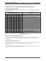
1
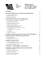
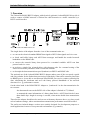
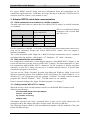
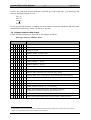
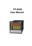
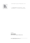
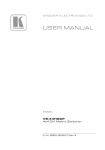
FALCON NET
- Isolated RS485-RS232 Adapter -
User manual*)
Revision: 03 December 2008
*)
Subject to technical change
via
traffic
controlling
gmbh
Maybachstrasse 39
D-51381 Leverkusen
Tel. +49 - (0)2171 - 50 49 30
Fax. +49 - (0)2171- 50 49 50
Email: [email protected]
1 OVERVIEW
1
2 ADAPTER ELEMENTS, LEDS, CONNECTORS AND SWITCHES
2
2.1 Connectors and pin connection
3
2.2 Baudrate switch settings
4
2.3 Bus termination resistors
4
3 ADAPTER RS232 SERIAL DATA COMMUNICATION
5
3.1 Cable connection to a terminal or a traffic controller
5
3.2 Data transmission and software
5
3.3 Getting started with a PC or Laptop
5
3.4 Adapter detector data output
6
3.5 Adapter detector parameter input or request
7
3.6 Adapter configuration and parameters
3.6.1 Checksum selection for the network binary protocol
3.6.2 Terminal echo
3.6.3 Delimiter, output data field separation
3.6.4 Gap units
3.6.5 Handshake
7
8
8
9
9
9
3.7 Adapter error messages
10
4 ADAPTER RS485 BINARY PROTOCOL (SEE FALCON NET MANUALS)
10
5 ADAPTER HOUSING, DIMENSIONS AND MOUNTING
10
5.1 Housing dimensions
11
5.2 Plug-in connector technical data
11
6 ADAPTER TECHNICAL DATA
12
6.1 Data processing and transmission
12
6.2 Power supply and interface electronic protection
12
6.3 Power supply and interface ratings
13
7 APPENDIX A - HYPERTERMINAL CONFIGURATION
14
8 APPENDIX B - UNDOCUMENTED FALCON NET FUNCTIONS
16
8.1 Binary data block format
16
8.2 Function ‘send still alive message’
16
8.3 Function ‘message counter’
16
8.4 Function ’suppress message repeat’
17
8.5 Function ‘set detector address’
17
Isolated Falcon Net Adapter
- -
9 APPENDIX C - DECLARATION OF CONFORMITY (CE)
via traffic controlling GmbH - Maybachstr. 39 - 51381 Leverkusen -
July 2004
17
+49-(0)2171-5049-30 Fax: -50
Isolated Falcon Net Adapter
-1-
September 11
1 Overview
The Falcon Net RS485-RS232 Adapter with electrical (galvanic) isolated RS485 driver side is
used to connect a RS485 network of Falcon Net radar detectors to a traffic controller by a
RS232 serial interface.
Illustration 1: Falcon Net RS485 network bus
The single duties of the adapter from the view of data communication are:
to convert the electrical standard RS485 data signal to RS232 data signals and vice versa.
to check and buffer binary and ASCII data messages and handle the needed network
handshake on the RS485 side.
to convert the network binary data protocol in a terminal readable ASCII text data
protocol and vice versa.
to work as a simple line oriented editor with character echo for a manual setting of the
Falcon Net detector parameters with a connected terminal.
to decouple the data transmission speed (baudrate) on RS232 and RS485 side.
The optional use of the isolated RS485-RS232 adapter makes sense if the user needs a quick
and easy solution for the further data processing. Particularly if the traffic controller (host) has
no RS485 port or is not able to run interrupt based RS485 port service routines collecting the
data, calculating the checksum and serve the binary protocol handshake of the network
detectors for e. g. performance reasons.
On the other hand is the RS485-RS232 Adapter a „bottleneck“ in the data transmission for
two reasons
- the data transfer rate on the RS232 side of the adapter is limited to 57,6 kbaud
- to transmit the same information of a binary data block, a ASCII data block of more
than double byte length in average is needed, what means double data transmission
time
Therefore the adapter should not be used on nets with many detectors above very busy roads
at low baudrate settings, where maximum data transmission performance would be needed..
The earlier not isolated adapter versions were mainly designed for development purposes or
small applications in more or less protected environments (e.g. tunnels).
via traffic controlling GmbH - Maybachstr. 39 - 51381 Leverkusen -
+49-(0)2171-5049-30 Fax: -50
Isolated Falcon Net Adapter
-2-
September 11
Although the RS485 driver lines of the earlier adapters were protected against transient surges
by suppressor diodes they had no electrical isolated RS485 driver. Transient surges (overvoltage pulses) can result from lightning discharge, switching operations or any capacitive,
inductive or resistive coupling in an electric systems. Transient surges have fast rise times of
a few µs and endure till 100 µs.
At maximum RS485 baudrate of 115.2 kbaud the cable length of the RS485 bus could be
extended till 1 km, or much more at lower data transmission rates. The potential ground
difference between the not isolated adapter host ground and the detector client ground was
limited to +/- 15 Volt. Otherwise the RS485 driver would have been damaged. For the new
isolated adapter less care must be taken because the isolations withstands 2,75 kV DC
potential difference.
If the suppressor diodes (600W) were thermally destructed at the earlier not isolated adapter,
(e.g. by permanent current flow due to too high potential differences between the RS485
drivers connected to the net) transients or over-voltages could damage the adapter, maybe also
over the power supply or the RS232 interface other electrical systems. For the new adapter
this kind of damages can be excluded.
The new isolated adapter features isolated potential free RS485 communication lines, overvoltage protected power input as well as transient surge protected RS232 data interface.
Additionally the adapter configuration parameters are now non-volatile EEPROM based.
2 Adapter elements, LEDs, connectors and switches
An operation control of the adapter is
possible with the 5 status LEDs
visible on the front side.
The green power (PWR) LED is lit as
soon the microcontroller (cpu) of the
adapter is started.
The two groups of LEDs labelled
RS232 and RS485 indicate data
transmission (Tx) or reception (Rx)
on either communication side.
All LEDs are directly controlled by
the cpu. Therefore if the cpu is
broken where will be also no
indication of data reception anymore.
The adapter has 4 male connector
sockets, which allow to plug-in 4
vibration safe female connectors.
Illustration 2: Isolated Falcon Net RS485-R232 Adapter
The transparent front clap window
should be kept closed for humidity
and dust protection of the switches.
via traffic controlling GmbH - Maybachstr. 39 - 51381 Leverkusen -
+49-(0)2171-5049-30 Fax: -50
Isolated Falcon Net Adapter
-3-
September 11
2.1 Connectors and pin connection
Illustration 2 shows 3 out of 4 possible mounted connectors, their numbers and labels and the
pin numbers. The description of the pin connections follows in Table 1.
Connector terminal
Pin
Description
1 - Power and RS232
1
0 V, ground
1 - Power and RS232
2
8V-38V, supply voltage
1 - Power and RS232
3
RxD, RS232 receive data
1 - Power and RS232
4
TxD, RS232 transmit data
2 - RS485 and USB Controller
1
Data-, USB, yet not supported, do not use
2 - RS485 and USB Controller
2
Data+, USB, yet not supported, do not use
2 - RS485 and USB Controller
3
RS485 Terminal A, yet not supported, do not use
2 - RS485 and USB Controller
4
RS485 Terminal B, yet not supported, do not use
3 - RS485 Falcon network
1
RS485 Terminal A
3 - RS485 Falcon network
2
RS485 Terminal B
3 - RS485 Falcon network
3
RS485 Terminal A
3 - RS485 Falcon network
4
RS485 Terminal B
4 - RS485 Falcon network
1
RS485 Terminal A
4 - RS485 Falcon network
2
RS485 Terminal B
4 - RS485 Falcon network
3
RS485 Terminal A
4 - RS485 Falcon network
4
RS485 Terminal B
Table 1: Isolated network adapter pin connections
The adapter will be delivered in general with 3 female screw-cage plug in connectors.
Connector 1 (Power and RS232) is for the power supply and the RS232 serial interface.
Connector 3 and 4 offer the possibility to connect up to 4 RS485 bus cables to the Pins
Terminal A and B. If this is done the network has no proper bus topology anymore (4 parallel)
buses, what results in impedance mismatch, but works in practice with short cables.
Proper bus topology means one cable connected and the adapter is located at one bus end.
Still proper is to have the adapter at any point of the bus with two cables of two network parts
connected. For proper RS485 network design and more information see for example the
application note „Guidelines for Proper Wiring of an RS-485 (TIA/EIA-485-A) Network“
from the website „www.maxim-ic.com“.
Connector 2 of the adapter is covered and reserved for future interface designs.
via traffic controlling GmbH - Maybachstr. 39 - 51381 Leverkusen -
+49-(0)2171-5049-30 Fax: -50
Isolated Falcon Net Adapter
-4-
September 11
2.2 Baudrate switch settings
The position of hexadecimal coded turn switch with marked positions 0 ... F determines the
data transmission speeds (baudrates1) on the RS485 Falcon network side and on the RS232
side. For each side a choice of 4 selections can be made. The meaning of the single switch
positions follows in Table 2.
Baudrate
RS485 network side Baudrate RS232 interface
switch position
[Baud]
[Baud]
0
1
2
3
4
5
6
7
8
9
A
B
C
D
E
F
9600
19200
57600
115200
9600
19200
57600
115200
9600
19200
57600
115200
9600
19200
57600
115200
4800
4800
4800
4800
9600
9600
9600
9600
19200
19200
19200
19200
57600
57600
57600
57600
Table 2: Baudrate switch settings
The baudrate switch is labelled „input/output baudrates“ on the adapter front view, see also
Illustration 2.
The Baudrates of receiver and transmitter in a communication connection must be set equal.
On the RS485 Falcon network side equal to the baudrate of the Falcon Net detectors, as
determined by their baudrate setting switch. On the RS232 side equal to the terminal or traffic
controller baudrate setting.
2.3 Bus termination resistors
Illustration 2 shows a 2 pole dip switch labelled „input resistance“.
If the upper switch labelled 240 Ohm is in „On“ position, a resistor of 240 Ohm is connected
between „Terminal A and B“. The lower switch connects a 120 Ohm resistor between pins
„Terminal A and B“. Therefore moving both switches in „On“ position results in 80 Ohm.
A proper network bus should be ended at each bus end with a termination resistor of 120
Ohm, resulting in the maximal allowed load of 60 Ohm between Terminal A and B wire. The
120 Ohm line termination (=R/2) relates to the impedance of a 24AWG RS485 cable. The
proper bus cable termination avoids signal reflections and in consequence signal
deformations.
1
bits per second
via traffic controlling GmbH - Maybachstr. 39 - 51381 Leverkusen -
+49-(0)2171-5049-30 Fax: -50
Isolated Falcon Net Adapter
-5-
September 11
For proper RS485 network design and more information about bus termination see for
example the application note „Guidelines for Proper Wiring of an RS-485 (TIA/EIA-485-A)
Network“ from the website „www.maxim-ic.com“.
3 Adapter RS232 serial data communication
3.1 Cable connection to a terminal or a traffic controller
The table aside shows how to connect the Falcon RS485-RS232 Adapter to a traffic controller
or a terminal.
9-pole DSUB connector
Adapter connector1 Power and RS232
Signal
Pin
Signal
Pin
RxD
2
TxD
4
TxD
3
RxD
5
GND
5
GND
1
This is a so-called null modem
connection with crossed RxD
and TxD wires.
For the connection a shielded 3-wire cable is needed. Further data transmission control wires
need not be connected, because the Falcon RS485-RS232 Adapter does not support a
hardware handshake.
The critical maximum cable length for a RS232/V24 data transmission can be estimated
according following formula: cable length = 106 / Baudrate = 106 / 9600 100 meter
3.2 Data transmission and software
For configuration, maintenance or data logging purposes of the RS485-RS232 adapter or the
Falcon Net detectors you may wish to connect a PC or laptop. The data transmission is a pure
text transmission with printable ASCII - characters. For the reception, to display and insert
characters on your PC or laptop you may use a so-called terminal software. A specific data
transmission program is not needed.
You may use the "Hyper Terminal" program from Microsoft Windows, which is part of all
Windows operating systems from Windows 95/NT till Windows XP. Under Windows 3.1 or
Windows 3.11 for workgroups exists the program "Terminal". For DOS countless terminal
programs like "Norton Terminal", "Telix", "XCOM" and so on, are available.
How to start and configure the „Hyper Terminal program“, see chapter 7.
3.3 Getting started with a PC or Laptop
When the wiring is done and the baudrate switch is set the RS485-RS232 adapter sends
following start message:
!Isolated RS485-RS232 Falcon Net Adapter
!Version: 1.01 07/29/04
!by via traffic controlling
!Adapter ready
All adapter messages start with a quotation mark, so they can be easily filtered out. All
messages send by the adapter end with a carriage return, line feed (0A 0D hex).
The following chapters shall be read and understood together with the manuals of the used
Falcon Net detector type.
via traffic controlling GmbH - Maybachstr. 39 - 51381 Leverkusen -
+49-(0)2171-5049-30 Fax: -50
Isolated Falcon Net Adapter
-6-
September 11
If there are connected network detectors, powered up at the same time, you should get the
detector startup messages as well:
M;1;01
M;2;01
M;3;01
M;n;01
If you get garbled messages or nothing on your terminal, check the baudrates and other data
transmission parameters ( 8 data , No parity, 1 stop bit).
3.4 Adapter detector data output
Falcon Net detector data are delivered by the adapter as follows:
data type; detector address; data
Meaning1
Data block
M;
d ;
d
general message no. 0-255
F ;
d ;
d
error message no. 0-255
W;
d ;
d
warning no. 0-255
P ; d ;
A f
parameter ADJF_A 0.001-9.999
P ; d ;
B f
parameter ADJF_B 0.001-9.999
P ; d ;
S d
parameter SENS 1-16
P ;
d ;
R d
parameter RSEG 5 - 80 cm
P ;
d ;
M d
parameter MSEG 5 - 40 cm
P ;
d ;
G d
parameter GAPL 5-255 in 10 ms units
P ;
d ;
D d
parameter DETE, 0/1, detection off/on
P ;
d ;
C d
parameter CRC checksum, 0/1/2 for LRC/CRC setting
P ;
d ;
I d
parameter DIR, 1/2/3 oncoming/leaving/bi-directional traffic detection
P ;
d ;
U N d
parameter detector network address 2, range 1-15
P ;
d ;
U S d
parameter „send still alive message“², 0/1, off/on
P ;
d ;
T d
detector self test report, correct result must be 45
P ;
d ;
V f
detector software version, e. g. 3.11, read only
D ;
d ;
d ;
f
measure data unidirectional modes (oncoming or leaving) speed in km/h, reflection value, net gap 0.00-655.35 s
O ;
d ;
d ;
f
measure data bi-directional modes, oncoming vehicle - data see above
L ;
d ;
d ;
f
measure data bi-directional modes, leaving vehicle - data see above
with d - decimal ASCII integer value, f - decimal ASCII float value
1
listed parameters and their value range refer to the detector Falcon Net II and III, for the Falcon Net I see its manual
2
see list of yet undocumented functions in chapter 8 for description
via traffic controlling GmbH - Maybachstr. 39 - 51381 Leverkusen -
+49-(0)2171-5049-30 Fax: -50
Isolated Falcon Net Adapter
-7-
September 11
All binary detector data values are reformatted by the adapter and delivered as ASCII decimal
or float values, the variable length of the ASCII strings depends on the data and address
values ( 1-15).
The LRC or CRC checksums for binary data blocks on the RS485 network is tested and the
receipt (detector address handshake) is given. For the RS 232 side no checksum is supported.
For the description of the parameters refer to the Falcon Net I, II or III manual, chapter
„program parameter set“. For the description of Falcon Net detector error and message
numbers refer also to manual of the used Falcon Net type.
3.5 Adapter detector parameter input or request
The command line input to initialise or change the Falcon Net detector parameter set is as
follows:
Start letter ‘A’, detector address, ‘P’, parameter type, parameter value
The command line request to get the data of the detector parameter set is as follows:
Start letter ‘A’, detector address, ‘?’, parameter type
For the parameter type the first letter of the detector parameter name for example ‘D’ for
DETE (Detection on/off) has to be used, see also Falcon Net manuals. One exception is the
parameter DIR where the letter ‘I’ must be used.
- Example 1:
Set the parameter SENS = 2 for detector no. 8:
‘A8PS2’
- Example 2:
Request the parameter setting of ADJF_A for all detectors:
‘A0?A’
All lowercase input letters are automatically converted to uppercase by the adapter. The
backspace character can be used to delete wrong characters in the adapter input line buffer.
Input lines must be completed with carriage return or line feed (<Enter> key). There is no
time limit for the completion of an input string.
Data messages from the detectors may split an command insertion on a connected terminal.
3.6 Adapter configuration and parameters
In contrary to earlier adapter versions the isolated RS485-RS232 Falcon net adapter parameter
are EEPROM based and therefore non-volatile. The parameter set integrity is checked after
power-on and after parameter changes with a 16 Bit CRC checksum.
When receiving an ESC (1B hex) character a short menu with the current parameter setting is
send from the adapter to a connected terminal
! Parameters
!<C> Checksum: CRC 1021h
!<D> Delimiter: ‘;’
!<E> Echo: on
!<G> Gap units: 10 ms
!<H> Handshake: on
!<R> Return
!Select:
Inserting ‘C, D, E, G or H’ selects the options prescribed in the following chapters. Automatic
programming sequences may send <ESC> and selection character without delay and ignore
the menus.
via traffic controlling GmbH - Maybachstr. 39 - 51381 Leverkusen -
+49-(0)2171-5049-30 Fax: -50
Isolated Falcon Net Adapter
-8-
September 11
Inserting ‘R’ returns from menu selection and <ESC> ‘R’ can be used to have the current
parameter setting listed.
3.6.1 Checksum selection for the network binary protocol
Several data block checksum types for the RS485 network communication are supported. The
escape sequence ESC C (1B 43 hex) sends a menu, where the checksums can be chosen:
! Select Checksum:
!<0> LRC
!<1> CRC 1021 hex
!<2> CRC-CCITT1
! Choose 0,1 or 2? 2
! CRC-CCITT set
After selection the current active checksum for the adapter is changed as well as the
checksums for all detectors in the network.
All data blocks from the detectors to the adapter are ended at the last byte position(s) with a
communication error checksum.
The one byte LRC checksum is calculated from all data block bytes with the bitwise logical
antivalenz function as follows:
LRC-byte = Byte 1 xor Byte 2 xor Byte 3 xor........ Byte n
Name
CRC 1021h
CRC-CCITT
Width
16 Bit
16 Bit
Poly
1021 hex
1021 hex
Init
0x0000 hex
0xffff hex
RefIn
False
False
RefOut
False
False
XorOut
0x0000 hex
0x0000 hex
Check
0x31c3
0x29b1
Table 3: CRC parameter model
The aside 16 Bit CRC checksums are generated with
a serial bitwise modulo-2 division by the
polynomial: x16+x12+x5+1. Despite the fact that the
generator polynomial is defined exist many different
ways to calculate the checksum.
Therefore Table 3 states the CRC generation
according the Ross Williams „Parameterized Model
For CRC Algorithms“. For more information check
e.g. the websites www.ross.net/crc for the document
„A painless guide to CRC error detection
algorithms“
or
the
site
rcswww.urz.tudresden.de/~sr21/crc.html for sample checksum
calculations.
The CRC-CCITT is the checksum build as recommended in the ITU (former CCITT)
recommendations X.25 and T.30.
Preferably the CRC checksum 1021h should be chosen, because its error detection probability
is with 99,9969% till 100% depending on the error type much higher than of the LRC and it is
supported by all Falcon Net detector types.
3.6.2 Terminal echo
Every data input character from a connected terminal is echoed (start-up default). You can
switch off the echo with the input sequence ESC E (1B 45 hex) and the adapter message !Echo
off will appear. This is a toggle switch, therefore repeating the action switches the echo on
again. The escape characters by themselves are never echoed.
1
The 8408 generator polynomial is not supported anymore
via traffic controlling GmbH - Maybachstr. 39 - 51381 Leverkusen -
+49-(0)2171-5049-30 Fax: -50
Isolated Falcon Net Adapter
-9-
September 11
3.6.3 Delimiter, output data field separation
The default delimiter (‘;’, semicolon) for the data output can be changed. The escape
sequence ESC D ‘delimiter’ will be prompted with ‘Insert delimiter:’. The insertion of a new
delimiter changes the so far delimiter to the new one. Following delimiters are possible:
horizontal tab (0B hex), space (20 hex), colon (2C hex) and semicolon (hex 3B).
If the delimiter is changed, the new delimiter is stated, e.g. !Delimiter: ‘\t’ for horizontal tab.
Especially for a tabular formatted data output the horizontal tab delimiter will be of interest.
3.6.4 Gap units
All Falcon Nets transfer a 2 byte counter for the inter vehicle net time gap. The Falcon Net I
transfers the gap in 50 ms units, range 0 ... 3276,75 seconds, the Falcon Net II and III delivers
the gap in 10 ms units, range 0 ... 655,35 seconds. The adapter delivers the gap in seconds as
an ASCII floating point value. For the correct calculation the gap units must be selected. With
<ESC> ‘G’ following menu appears:
!Select GAP units:
!<1> 50 ms (Falcon Net I)
!<2> 10 ms (Falcon Net II and III)
! Choose 1 or 2: 2
If ‘2’ is chosen „! 10 ms GAP units set“ is confirmed.
3.6.5 Handshake
With the insertion <ESC> ‘H’ the RS485 software handshake of the binary protocol can be
switched off. If switched off the adapter sends „!Handshake off“. This option is a toggle
switch.
Data blocks send from the detectors to the adapter are then not confirmed with the detector
address anymore. This option is useful when you operate more than one adapter in a Falcon
network, e.g. for data logging or test purposes, to avoid that the handshake is done more than
once, respectively the address byte is destroyed by synchronous adapter bus accesses.
via traffic controlling GmbH - Maybachstr. 39 - 51381 Leverkusen -
+49-(0)2171-5049-30 Fax: -50
Isolated Falcon Net Adapter
- 10 -
September 11
3.7 Adapter error messages
Error messages
Meaning
! Adapter RS232 line too long
The input line length was more than 18
characters, for this reason the line was erased
! Adapter RS485 receive buffer overflow
Though the RS485 FIFO input buffer is 60
data blocks deep, an overrun occurred, you
need to increase the RS232 data transmission
speed or take out some detectors of the net
! Adapter watchdog failure
Watchdog message that a system „hang up“
occurred
! Adapter power failure
! Adapter default parameter set
The microprocessor power supply sank below
4,5 Volt. Check the power supply.
If the message appears after the first factory
initialisation it indicates that the EEPROM
CRC parameter checksum is wrong.
4 Adapter RS485 binary protocol (see Falcon Net manuals)
Please refer to the Falcon Net manuals for the description of the binary data protocol,
parameters and values, handshake and timing.
A description of the not in the manuals documented functions are found in chapter 8.
5 Adapter housing, dimensions and mounting
The light grey polyamide adapter housing is designed for the fast plug-in mounting on 35 mm
DIN mounting rails.
The adapter back is equipped with a springforce snap-in lock. With a screw driver
pulled against the spring-force the adapter
can easily taken off the mounting rail.
The housing is designed for the use in
protected cabinets. Therefore the protection
class is just IP43 if mounted on the carrier
rail.
Illustration 3: Spring force snap-in lock
via traffic controlling GmbH - Maybachstr. 39 - 51381 Leverkusen -
+49-(0)2171-5049-30 Fax: -50
Isolated Falcon Net Adapter
- 11 -
September 11
5.1 Housing dimensions
The housing dimension are 99 x 22,5 x 113,6 mm. The total length mounted on the carrier rail
Illustration 4: Housing drawing
is 114,5 mm. Additional space of 20 till 30 mm must be foreseen below and above for the
installation of the plug-in connectors with cable. The weight of the adapter is 125 gr without
connectors.
5.2 Plug-in connector technical data
The used connector are Phoenix MC 1,5/-ST-5,08. Their data follow in Table 4.
Connector
Phoenix MC 1,5/-ST-5,08
Grid space
5,08 mm
Min/Max wire diameter (flexible or rigid)
0,14 - 2,5 mm², AWG 24-12
Wire sheath cutting length
7 mm
Max. operating voltage/current
250 V / 8 A
Table 4: connector technical data
via traffic controlling GmbH - Maybachstr. 39 - 51381 Leverkusen -
+49-(0)2171-5049-30 Fax: -50
Isolated Falcon Net Adapter
- 12 -
September 11
6 Adapter technical data
6.1 Data processing and transmission
RS232 side
RS485 side
8 data-, 1 stop-, no parity bit
8 data-, 1 stop-, no parity bit
two-point
multi-point/network
Data transmission speed
4.8, 9.6, 19.2 or 57.6 kbaud
9.6, 19.2, 57.6 or 115,2 kbaud
Measurement data
format
ASCII, decimal, 1 line per
vehicle, default delimiter: ‘;’
‘D’;(address);(speed);
(reflection); (gap)..CRLF
binary, 1 data block per vehicle
with checksum and handshake
Data buffer size
transmit
1 ASCII line
10 data blocks (LIFO)
Data buffer size receive
1 ASCII line
40 data blocks (FIFO)
Maximum cable length
100 m @ 9600 Baud
1300 m @ 115,2 kBaud
Transmission procedure
asynchronous
full-duplex
XON/XOFF supported
asynchronous
half-duplex
CSMA/CD with handshake
Data format
Communication type
6.2 Power supply and interface electronic protection
Additionally the RS 232 driver lines are suppressor-diode (15 V, 600W) protected against
ground. The Terminal A against B line is also protected with 15 V suppressor-diode.
Power supply protection against
reverse connection:
Series-connected protective diode
Power supply EMC protection:
Varistor 38 V
Suppressor-diode 39 V (600 W, 1 ns response time)
Current compensated inductive coil filter
Power supply overload:
Miniature fuse 1 A on circuit board
EMC transient burst protection
RS485 bus and RS232 drivers:
8 kV contact discharge
15 kV air gap discharge
acc. IEC 1000-4-2
Isolation RS485 terminal lines:
2,75 kV DC
via traffic controlling GmbH - Maybachstr. 39 - 51381 Leverkusen -
+49-(0)2171-5049-30 Fax: -50
Isolated Falcon Net Adapter
- 13 -
September 11
6.3 Power supply, interface and general ratings
Rating
Minimal
Typical
Maximal
Units
10
12
38
V DC
Current consumption :
-
60
80
mA DC
Input ripple voltage:
-
-
100
mVpp
Power supply input voltage range:
1
RS485 driver
MAX481
Number of transceiver on bus
-
-
Driver output voltage (A, B)2
-8
12
V
Receiver input voltage (A,B)2, 3
-8
12
V
Differential driver output voltage
1,5
-
5
V
Receiver Input sensitivity
- 200
70
+ 200
mV
Driver short circuit current
35
250
mA
Input resistance
12
Driver load
54
kOhm
60
RS232 driver
+/- 5
RxD input voltage range
RS232 input resistance
Operating temperature range
Ohm
MAX202
TxD output voltage swing 4
RxD input hysteresis
32
-
V
- 30
+ 30
V
low < 0,8
high > 2,4
V
7
kOhm
+ 85
°C
95
%
3
+/- 8
5
- 40
Rel. humidity (non condensing)
MTBF (MILHDBK-217F)
Housing protection (EN60529)
1
RS232 and RS485 connected
2
Against isolated ground, potential free
3
Suppressor diode connected with +/- 15 Volt limitation
4
with 3 kOhm load
239.000
Hours
IP50
via traffic controlling GmbH - Maybachstr. 39 - 51381 Leverkusen -
+49-(0)2171-5049-30 Fax: -50
Isolated Falcon Net Adapter
- 14 -
September 11
7 Appendix A - Hyper Terminal configuration
To find the "Hyper Terminal" in the Microsoft Windows task bar, click on the start button in
the task bar and then Programs - Accessories - (Communication) - Hyperterminal.
Illustration 5
Illustration 6
Start the program with a mouse click.
If you use the program the very first time a message prompt appears with the question if you
want to define a modem connection. Quit with the "No" button.
Insert in the dialogue "Connection description" a name for the session and chose an icon, see
also Illustration 5.
Confirm with the "OK" button.
In the next window you have to define the interface to which the connection shall be done.
Select a defined port designation in the selection field "Connect using", e.g. COM1 or COM2.
The other input fields are shaded grey in consequence, because they are not needed for direct
port connection, this fields are only used with modems, see Illustration 6.
Finally you have to insert or chose the data transmission parameters.
via traffic controlling GmbH - Maybachstr. 39 - 51381 Leverkusen -
+49-(0)2171-5049-30 Fax: -50
Isolated Falcon Net Adapter
- 15 -
September 11
Illustration 7
Use the baudrate value as set by the baudrate switch for the RS232 communication, see
chapter 2.2, the other data format parameters set as shown in Illustration 7 (8-N-1-Xon/Xoff).
After this is done and the "COM properties" dialogue is ended with the "OK" button the
empty terminal screen appears.
Connect the Falcon net RS485-RS232 adapter with the prepared cable to the serial COM port
of your PC and supply the adapter with power.
via traffic controlling GmbH - Maybachstr. 39 - 51381 Leverkusen -
+49-(0)2171-5049-30 Fax: -50
Isolated Falcon Net Adapter
- 16 -
September 11
8 Appendix B - Yet undocumented Falcon Net functions
8.1 Binary data block format
Following functions and parameters are added to the one described in the digital Falcon Net
reference guide:
Data block byte position
1 2 3 4 5 6 7
B
X
X
X
P
U
S
R
A
N
?
U
S
R
A
N
Following shortings are used:
Meaning
8 9 10 11 12 13
X
X
X
X
E
E
E
E
start byte uppercase ´B´ (hex 42)
target address byte (0-15 detectors, 33-255 hosts)
source address byte (0-15 detectors, 33-255 hosts)
data block length, including LRC/CRC-checksum
P - command set parameter or parameter report message
U - undocumented function
S-‘send still alive message’, 0/1 for de- / activated
R-’message counter’, 0/1 for de- / activated
A-’suppress message repeat’ , 0/1 for off/on
N-’set detector address’, range 0...15
? - command parameter status requested
U - undocumented function
send status of ‘send still alive message’ function
send status of ’message counter’ function
send status of ’suppress message repeat’ function
send programmed detector address
E
E
E
E
X - hexadecimal number 0-255 (0-FF hex)
E - LRC (0-FF hex, 1 byte) or
CRC (0-FFFF hex, 2 byte) checksum
8.2 Function ‘send still alive message’
Activated this function forces the digital Falcon Net II to send the result of the cyclic all 327,68 seconds done
‘self test’ to the host system. Self test and result report are described in the Falcon Net II reference guide.
Default setting: off
8.3 Function ‘message counter’
Activated this function adds a 4-bit message upcounter (0,1,...15,0,1,...) for every new created message from the
detector to the host in the upper nibble of the data block length byte (data block byte no.4).
Default setting: off
The LRC/CRC checksums are created over the send message including the message counter. The Falcon Net II
Adapter version 3.01 ff ignores an added message counter.
via traffic controlling GmbH - Maybachstr. 39 - 51381 Leverkusen -
+49-(0)2171-5049-30 Fax: -50
Isolated Falcon Net Adapter
- 17 -
September 11
8.4 Function ’suppress message repeat’
The suppress message repeat function forces the Falcon Net II detector not to wait for a response (send back
detector address) of the connected host to his messages. Herewith he also does not repeat already send messages
because he does not get the host response (‘Acknowledge’). Messages are only repeated if the sending detector
states a message collision when he reads back his message bytes from the data bus.
Default setting: off
8.5 Function ‘set detector address’
The digital Falcon Net II detector can be programmed to a network detector address in a two point connection
before installed in a network. If the address is set (not 0) the EEPROM based adress overrides the hex-switch set
detector address on the interface socket. If this address is reset to 0 by the undocumented function ‘N’ then the
set hex switch adress is valid again. This function cannot/shall not be used in the network.
Default setting: 0 (not valid/active = hex-switch setting active)
The address change gets valid with the parameter ‘N’ set response.
9 Appendix C - Declaration of conformity (CE)
Declaration of Conformity
The manufacturer:
Via traffic controlling GmbH
Declares that the product: Isolated RS485-RS232 Falcon Net Adapter
Intended purpose:
Network communication adapter
Complies with
- Health and safety requirements according low voltage directive 2006/95/EC
- Protection requirements concerning electromagnetic compatibility, according
electromagnetic compatibility directive 2004/108/EC
Harmonised standards applied:
EN 60950-1: 2006-11+A1: 2007-11
EN 55022: 2007-04
EN 61000-6-4/-2 :2002-08/2006-03
Address:
Via traffic controlling
Maybachstraße 39
D-51381 Leverkusen
Place, date of issue: Leverkusen, 03 December 2008
Name and signature: Dipl.-Ing. (FH) J. Geßler
via traffic controlling GmbH - Maybachstr. 39 - 51381 Leverkusen -
+49-(0)2171-5049-30 Fax: -50