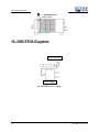
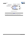
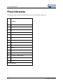
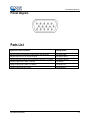
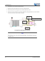
1
Halogen Light Source with Attenuator and TTL-Shutter Installation and Operation Manual For Products: HL-2000-FHSA / HL-2000-FHSA-LL / HL-2000-FHSA-HP Document: 000-10000-070-02-201504 000-00000- AMERICAS & WORLD HEADQUARTERS Ocean Optics, Inc. Phone: +1 727-733-2447 Fax: +1 727-733-3962 Sales: Orders: Support: [email protected] [email protected] [email protected] EUROPE, MIDDLE EAST & AFRICA 830 Douglas Ave. Dunedin, FL 34698 USA Manufacturing & Logistics 4301 Metric Dr. Winter Park, FL 32792 USA Sales & Support Phone: +31 26-319-0500 Fax: +31 26-319-0505 Email: [email protected] Geograaf 24 6921 EW Duiven The Netherlands Germany : +49 711-341696-0 UK : +44 1865-811118 France : +33 442-386-588 Manufacturing & Logistics Maybachstrasse 11 73760 Ostfildern Germany ASIA Phone: +86 21-6295-6600 Fax: +86 21-6295-6708 Email: [email protected] Japan & Korea: +82 10-8514-3797 Ocean Optics Asia 666 Gubei Road Kirin Tower Suite 601B Changning District Shanghai PRC, 200336 www.oceanoptics.com Copyright © 2006 Ocean Optics, Inc. All rights reserved. No part of this publication may be reproduced, stored in a retrieval system, or transmitted, by any means, electronic, mechanical, photocopying, recording, or otherwise, without written permission from Ocean Optics, Inc. Trademarks All products and services herein are the trademarks, service marks, registered trademarks or registered service marks of their respective owners. Limit of Liability Every effort has been made to make this manual as complete and as accurate as possible, but no warranty or fitness is implied. The information provided is on an “as is” basis. Ocean Optics, Inc. shall have neither liability nor responsibility to any person or entity with respect to any loss or damages arising from the information contained in this manual. . Important Safety Notices 1. Do not remove or modify any installed safety device on this equipment. Doing so will void your warranty and create an unsafe operating environment. 2. Dangerous voltages are present in this device. There are NO user serviceable parts inside. 3. Only allow qualified personnel to service this unit. 4. Do not use the unit if it is damaged in any way. Contact your dealer for repair or replacement information. Warranty Ocean Optics Germany GmbH warrants to the original user of this instrument that it shall be free of any defects resulting from faulty manufacture of this instrument for a period of 12 months from the original data of shipment. This instrument should not be used for any Clinical or Diagnostic purposes. Data generated in these areas is not warranted in any way by Ocean Optics Germany GmbH. Any defects covered by this Warranty shall be corrected either by repair or by replacement, as determined by Ocean Optics Germany GmbH. There are no warranties that extend beyond the description herein. This Warranty is in lieu of, and excludes, any and all other warranties or representations expressed, implied, or statutory, including merchantability and fitness, as well as any and all other obligations or liabilities of Ocean Optics Germany GmbH including, but not limited to, special or consequential damages. No person, firm, or corporation is authorized to assume for Ocean Optics Germany GmbH. Any additional obligation or liability not expressed provided for herein except in writing duly executed by an officer of Ocean Optics Germany GmbH: Ocean Optics Germany GmbH Maybachstraße 11 D-73760 Ostfildern Tel.: +49 (0)711 34 16 96-51 • Fax.: +49 (0)711 34 16 96-85 e-mail: [email protected] 000-10000-070-02-201504 A Important Safety Notices B 000-10000-070-02-201504 Table of Contents About This Manual .............................................................................................................iii Document Purpose and Intended Audience .............................................................................. iii What’s New in this Document ................................................................................................... iii Document Summary .................................................................................................................. iii Product-Related Documentation ............................................................................................... iii Upgrades ............................................................................................................................iii Chapter 1: Setup ................................................................................... 5 Overview .............................................................................................................................5 Unpacking the HL-2000-FHSA ..........................................................................................5 Contents .............................................................................................................................6 Setting Up the HL-2000-FHSA Light Source .....................................................................6 Enabling Automatic Shutter Control ...................................................................................7 Optimizing the Optical Power Output .................................................................................8 Attenuating the Optical Power Output ...............................................................................9 HL-2000-FSHA Diagrams ..................................................................................................10 Chapter 2: HL-2000-FHSA Specifications .......................................... 13 Specifications .....................................................................................................................13 Pinout Information ..............................................................................................................14 Pinout Diagram .......................................................................................................................... 15 Parts List .............................................................................................................................15 Appendix A: Bulb Replacement ......................................................... 17 Overview .............................................................................................................................17 Replacing the Bulb .............................................................................................................17 Index ...................................................................................................... 19 000-10000-070-02-201504 i Table of Contents ii 000-10000-070-02-201504 About This Manual Document Purpose and Intended Audience This document provides you with an installation section to get your system up and running. What’s New in this Document This version of the Halogen Light Source with Attenuator and TTL-Shutter HL-2000-FHSA / HL-2000FHSA-LL / HL-2000-FHSA-HP Installation and Operation Manual updates logo and the contact information, and the bulb replacement instructions Document Summary Chapter Description Chapter 1: Setup Contains instructions for setting up the unit, enabling automatic shutter control, and optimizing and attenuating the optical power output. Chapter 2: HL-2000-FHSA Specifications Contains operating environment specifications, as well as other physical details of the product. Appendix A: Bulb Replacement Provides instructions for changing the bulb. Product-Related Documentation You can access documentation for Ocean Optics products by visiting our website at http://www.oceanoptics.com. Select Support Technical Documents, then choose the appropriate document from the available drop-down lists. Upgrades Occasionally, you may find that you need Ocean Optics to make a change or an upgrade to your system. To facilitate these changes, you must first contact Customer Support and obtain a Return Merchandise Authorization (RMA) number. Please contact Ocean Optics for specific instructions when returning a product. 000-10000-070-02-201504 iii About This Manual iv 000-10000-070-02-201504 Chapter 1 Setup Overview The following sections provide instructions on unpacking and setting up your HL-2000-FHSA Light Source. Before using the HL-2000-FHSA for the first time, check for transport damage. Be sure to adhere to all warnings on the unit and in this manual. Unpacking the HL-2000-FHSA ► Procedure 1. Unpack your lamp assembly carefully. Dropping this instrument can cause permanent damage. 000-10000-070-02-201504 5 2: HL-2000 Specifications 2. Inspect the outside of the instrument and make sure that there is no damage. Do not use the instrument if damage is present. Contact your dealer for repair or replacement information, if necessary. 3. Use this instrument in a clean laboratory environment. Contents Your HL-2000-FHSA package should contain the following: HL-2000 Light Source One IC-DB15-2 interface cable for shutter operation Setting Up the HL-2000-FHSA Light Source Use the following procedure and refer to HL-2000-FSHA Diagrams to set up your light source. ► Procedure Perform the steps below to set up your HL-2000-FHSA Light Source: 1. Plug the power supply into a wall outlet. Power Supply 2. Plug the other end of the power supply cable into the socket of HL-2000-FHSA. 6 000-10000-070-02-201504 2: HL-2000 Specifications HL-2000-FHSA Rear View 3. Connect the SMA connector of your fiber optic cable to the SMA plugs. HL-2000-FHSA Right Side View 4. Turn the Halogen lamp on using the power switch on the rear of the HL-2000-FHSA. HL-2000-FHSA Rear View Enabling Automatic Shutter Control The HL-2000-FHSA is equipped with a 15-pin TTL port on the rear of the unit that allows an external source to control the shutter of the HL-2000-FHSA. ► Procedure To enable automatic shutter control (TTL), perform the following steps: 000-10000-070-02-201504 7 2: HL-2000 Specifications 1. Insert the supplied IC-DB-15-2 15 pin connector into the port on the rear of the HL-2000-FHSA. HL-2000-FHSA Rear View 2. Move the shutter switch on the rear of the unit into the appropriate position to select the shutter mode. Open – Shutter open Close – Shutter closed TTL – Controlled by external TTL (High = Open, Low = Closed) Note Use Ocean Optics software to save a dark measurement. Optimizing the Optical Power Output The HL-2000-FHSA is adjusted at the factory to provide maximum power into a 200µm fiber. If a lower optical power is required or a different fiber (bundle) diameter is used, you can adjust the optical power of the unit. Refer to HL-2000-FSHA Diagrams while using the following procedure. ► Procedure Follow the steps below to adjust the optical power of the HL-2000-FHSA Light Source: 1. Connect a fiber optic spectrometer or an optical power meter to a fiber, and then connect the other end of the fiber to the HL-2000-FHSA’s SMA plug. 2. Loosen the blocking screw with the provided 1.3mm Allen wrench. 8 000-10000-070-02-201504 2: HL-2000 Specifications 3. Shift the SMA socket to optimize the optical power of the HL-2000-FHSA. 4. Tighten the blocking screw to secure the SMA socket position. Attenuating the Optical Power Output The HL-2000-FHSA allows you to attenuate the optical output of the unit by adjusting the attenuation screw. ► Procedure To attenuate the optical output of the HL-2000-FHSA, follow the steps below: 1. Ensure that the shutter switch on the rear of the unit is in the open position. 2. Loosen the fixture screw with the provided 2.0mm Allen wrench. 3. Turn the attenuation screw until the desire optical power is achieved. 4. Tighten the fixture screw when finished. 5. To attenuate the optical output of the HL-2000-FHSA, turn the attenuation-screw clockwise. Caution The attenuation screw can prevent the shutter form opening if turned clockwise too far. If the shutter is not working, turn the attenuation screw counterclockwise. 000-10000-070-02-201504 9 2: HL-2000 Specifications HL-2000-FSHA Diagrams Power Connector Power Supply HL-2000-FHSA Power Supply 10 000-10000-070-02-201504 2: HL-2000 Specifications HL-2000-FHSA Rear View Filter Holder Fixture Screw SMA Connector HL-2000-FHSA Side View 000-10000-070-02-201504 11 2: HL-2000 Specifications HL-2000-FHSA Bottom View Note Do not completely remove the bulb fixture screw. It may be hard to reinsert it. 12 000-10000-070-02-201504 2: HL-2000 Specifications Chapter 2 HL-2000-FHSA Specifications This section provides information on the operating environment, physical controls, and dimensions of the HL-2000-FHSA, as well as pinouts for the DB-15 connector. It also provides a parts list. Specifications HL-2000-FHSA HL-2000-FHSA-LL 360 nm – 2400 nm 0.5 % Wavelength range Stability Drift HL-2000-FHSA-HP <0.1% per hour Time to stabilize Approximately 5 Minutes Output to bulb 5V DC / 1,435A 5V DC / 0,970A 24V DC / 1,67A Bulb life time 1.500 h 10.000 h 2000 h Characteristic Focused Shutter TTL max. 5Hz DB-15 Connector Bulb color temperature PIN 13: TTL 2.960K Humidity Weight Size 000-10000-070-02-201504 2.800K 3.000K 5°C – 35°C Room temperature Output PIN 10: Ground 5 - 95% at 40°C 7W 7W 20W Approximately 0.5 kg 58 x 59 x 140 mm 13 2: HL-2000 Specifications Pinout Information The following table contains pinout information for the HL-2000-FHSA Light Source: Pin Description 1 na 2 na 3 na 4 na 5 na 6 na 7 na 8 na 9 na 10 Ground 11 na 12 na 13 TTL Signal – Shutter control 14 na 15 na na = not applicable 14 000-10000-070-02-201504 2: HL-2000 Specifications Pinout Diagram Parts List Spare Parts / Order Information Catalog Number Halogen light source with filter holder/shutter and attenuator HL-2000-FHSA Halogen light source, fan cooled, long life HL-2000-FHSA-LL Halogen light source High-Power with Attenuator and TTL-Shutter HL-2000-FHSA-HP Halogen spare bulb 2.960K/ 1.500 hrs HL-2000-B Halogen spare bulb 2.800K / 10.000 hrs HL-2000-LL-B Halogen spare bulb High-Power HL-2000-HP-B 000-10000-070-02-201504 15 2: HL-2000 Specifications 16 000-10000-070-02-201504 Appendix A Bulb Replacement Overview To order replacement bulbs for the HL-2000-FHSA, consult the Parts List. WARNING Before replacing the bulb in the HL-2000-FHSA, disconnect the lamp from your power source and allow the unit to cool for at least twenty minutes, if necessary. Replacing the Bulb ► Procedure Refer to Figure 5 and perform the steps below to replace the bulb in the HL-2000-FHSA Light Source: 1. Unplug the power connector from the power socket on the HL-2000-FHSA. 2. Loosen the screws on the rear of the unit with the provided 2.5mm Allen wrench. 3. Remove the rear of the HL-2000-FHSA and remove the electronics board from the unit, taking particular care not to disconnect the fan wires. 4. Loosen the bulb fixture screw from the bottom of the unit with the provided 1.3mm Allen key. Note Do not completely remove the bulb fixture screw. It may be hard to reinsert it. 5. Remove the bulb from the HL-2000-FHSA. 000-10000-070-02-201504 17 A: Bulb Replacement 6. Disconnect the wires from the connection block. 7. Replace the bulb and reconnect the wires to the connection block. 8. Slide the lamp into the housing and secure with the bulb fixture screw. 9. Slide the electronics board back into the HL-2000-FHSA, taking particular care to ensure that the wires do not come into contact with the fan blades. Connection Block Rear / Electronics Board Lamp Housing Fan Wires HL-2000-FHSA Bulb Replacement Diagram Note The bulb fixture screw is above the fan, behind the blades. Turn the blades, if necessary, to reach the screw. 18 000-10000-070-02-201504 Index B bulb replacement, 17 bulb replacement diagram, 18 D diagrams, 10 bottom view, 12 bulb replacement, 18 pinout, 15 power supply, 10 rear view, 11 side view, 11 document audience, iii purpose, iii summary, iii O optical power attenuating output, 9 optimizing output, 8 000-10000-070-02-201504 P package contents, 6 parts list, 15 pinout diagram, 15 pinouts, 14 product-related documentation, iii S setup, 5 shutter control, 7 specifications, 13 U unpacking procedure, 5 upgrades, iii W warranty, A what's new, iii 19 Index 20 000-10000-070-02-201504