1
MOD-IO
Open-source hardware UEXT extension board with relays and
USER’S MANUAL
Document revision B, May 2015
Designed by OLIMEX Ltd, 2014
All boards produced by Olimex LTD are ROHS compliant
OLIMEX© 2015
MOD-IO user's manual
DISCLAIMER
© 2015 Olimex Ltd. Olimex®, logo and combinations thereof, are registered trademarks of Olimex Ltd. Other product
names may be trademarks of others and the rights belong to their respective owners.
The information in this document is provided in connection with Olimex products. No license, express or implied
or otherwise, to any intellectual property right is granted by this document or in connection with the sale of
Olimex products.
This work is licensed under the Creative Commons Attribution-ShareAlike 3.0 Unported License. To view a copy of
this license, visit http://www.creativecommons.org/licenses/by-sa/3.0/.
This hardware design by Olimex LTD is licensed under a Creative Commons Attribution-ShareAlike 3.0 Unported
License.
The part of the example software that was written by Olimex is released under GPL. If there are parts of the software
belonging to other developers or companies they maintain their respective rights of the code.
It is possible that the pictures in this manual differ from the latest revision of the board.
The product described in this document is subject to continuous development and improvements. All particulars of the
product and its use contained in this document are given by OLIMEX in good faith. However all warranties implied or
expressed including but not limited to implied warranties of merchantability or fitness for purpose are excluded. This
document is intended only to assist the reader in the use of the product. OLIMEX Ltd. shall not be liable for any loss or
damage arising from the use of any information in this document or any error or omission in such information or any
incorrect use of the product.
This evaluation board/kit is intended for use for engineering development, demonstration, or evaluation purposes only
and is not considered by OLIMEX to be a finished end-product fit for general consumer use. Persons handling the
product must have electronics training and observe good engineering practice standards. As such, the goods being
provided are not intended to be complete in terms of required design-, marketing-, and/or manufacturing-related
protective considerations, including product safety and environmental measures typically found in end products that
incorporate such semiconductor components or circuit boards.
Olimex currently deals with a variety of customers for products, and therefore our arrangement with the user is not
exclusive. Olimex assumes no liability for applications assistance, customer product design, software performance, or
infringement of patents or services described herein.
THERE IS NO WARRANTY FOR THE DESIGN MATERIALS AND THE COMPONENTS
USED TO CREATE MOD-IO. THEY ARE CONSIDERED SUITABLE ONLY FOR MODIO.
Page 2 of 30
OLIMEX© 2015
MOD-IO user's manual
Table of Contents
DISCLAIMER............................................................................................................. 2
CHAPTER 1: OVERVIEW........................................................................................5
1. Introduction to the chapter.......................................................................................................5
1.1 Features.....................................................................................................................................5
1.2 Target market and purpose of the board...............................................................................5
1.3 Board variants..........................................................................................................................6
1.4 Board version used in the manual..........................................................................................6
1.5 Document organization........................................................................................................... 6
CHAPTER 2: SETTING UP THE MOD-IO BOARD.............................................7
2. Introduction to the chapter.......................................................................................................7
2.1 Electrostatic and electrical polarity warning........................................................................ 7
2.2 Hardware requirements.......................................................................................................... 7
2.3 Software requirements............................................................................................................ 8
2.4 Powering the board..................................................................................................................8
2.5 Changing the firmware........................................................................................................... 9
2.5 Connecting more than one MOD-IO together...................................................................... 9
2.6 Default firmware description..................................................................................................9
2.6.1 Setting relays.................................................................................................................................................10
2.6.2 Getting the state of optocoupler..................................................................................................................11
2.6.3 Reading the value of an analog input.........................................................................................................12
2.6.4 Changing the I2C address of a board.........................................................................................................13
2.7 Arduino with MOD-IO..........................................................................................................14
2.8 OLinuXino boards with MOD-IO........................................................................................14
CHAPTER 3: MOD-IO BOARD DESCRIPTION................................................ 16
3. Introduction to the chapter.....................................................................................................16
3.1 Layout (top view)...................................................................................................................16
CHAPTER 4: THE ATMEGA16A MICROCONTROLLER............................... 17
4. Introduction to the chapter.....................................................................................................17
4.1 The processor......................................................................................................................... 17
CHAPTER 5: CONNECTORS AND PINOUT......................................................19
5. Introduction to the chapter.....................................................................................................19
5.1 Communication with MOD-IO.............................................................................................19
5.2 AVRISP................................................................................................................................... 20
5.3 JTAG.......................................................................................................................................20
5.4 EXT......................................................................................................................................... 21
5.5 UEXT_MALE........................................................................................................................ 22
5.6 UEXT_FEMALE................................................................................................................... 22
5.7 Digital inputs, digital outputs and analog inputs................................................................22
5.7.1 IN1, IN2 IN3, IN4 – digital inputs...............................................................................................................23
5.7.2 OUT1, OUT2, OUT3, OUT4 – digital outputs...........................................................................................23
Page 3 of 30
OLIMEX© 2015
MOD-IO user's manual
5.7.3 AIN-1 and AIN-2 – analog inputs................................................................................................................23
5.8 PWR jack................................................................................................................................24
5.9 Additional hardware components........................................................................................ 24
CHAPTER 6: SCHEMATICS..................................................................................25
6. Introduction to the chapter.....................................................................................................25
6.1 Eagle schematic......................................................................................................................25
6.2 Physical dimensions...............................................................................................................27
CHAPTER 7: REVISION HISTORY AND SUPPORT........................................ 28
7. Introduction to the chapter.....................................................................................................28
7.1 Document revision................................................................................................................. 28
7.2 Board revision........................................................................................................................ 28
8.3 Useful web links and purchase codes...................................................................................29
8.4 Product support..................................................................................................................... 30
Page 4 of 30
OLIMEX© 2015
MOD-IO user's manual
CHAPTER 1: OVERVIEW
1. Introduction to the chapter
Thank you for choosing the MOD-IO extension module from Olimex! This document provides a
user’s guide for the MOD-IO board. As an overview, this chapter gives the scope of this document
and lists the board’s features. The document’s organization is then detailed.
The MOD-IO board allows easy expansion of the functionality of other boards by adding relays,
optocouplers and analog inputs.
MOD-IO is an open-source, open-hardware project and all documentation is available to the
customer.
1.1 Features
The board has the following set of features:
•
•
•
•
•
•
•
•
•
•
•
•
•
•
•
•
•
Open source hardware board with ATMega16L-8AU microcontroller
4-optocoupler isolated inputs with screw terminals
Input status LEDs
4-relay outputs with 5A/250VAC contacts with screw terminals
Output status LEDs
Stackable
ICSP 5×2 pin connector for in-circuit programming with AVR-ISP500 and AVR-ISP-MK2
or another compatible ICSP programmer
JTAG 5×2 pin connector for in-circuit programming with AVR-JTAG, AVR-JTAG-USB or
another compatible JTAG debugger
EXT extension connector for the unused AVR ports
Status LED
Reset IC ZM33064
Quartz crystal oscillator circuit 8MHz
DC-DC with input voltage 8-30VDC – this board can be powered from 24V industrial
power supplies
Power plug-in jack
Four mounting holes 3.3 mm (0.13")
FR-4, 1.5 mm (0.062"), red soldermask, white silkscreen component print
Dimensions 80×100 mm (3.9×3.15")
1.2 Target market and purpose of the board
The Olimex boards that carry the “MOD-” prefix in their product name are typically extension
boards with a UEXT connector. They are usually used to expand the functions of a “host board”
(another board with main microcontroller of its own and UEXT connector).
UEXT is a board to board connector which supports three serial communication interfaces - I2C,
SPI and RS232. It is a great way to expand the features of the development boards you already
Page 5 of 30
OLIMEX© 2015
MOD-IO user's manual
have. The customer can choose which new feature he wants to expand. More on the UEXT might be
found in the following document:
https://www.olimex.com/Products/Modules/UEXT/resources/UEXT_rev_B.pdf
MOD-IO provides 4 relays with proper connector that allow the switching of circuits. The board is
also equipped with 4 optocouplers (also known as opto-isolators) that transfer electrical signals
between two isolated circuits by using light. MOD-IO also has 4 analog inputs won a connector.
MOD-IO comes with built-in firmware which makes the usage of the board's peripherals much
easier. It uses a standard I2C communication and several commands are defined. The source of the
firmware is also available to the customer.
Customers have full access to the technical documentation of the board. The software is released
under General Purpose License and the board is considered open-hardware – all schematics and
board design files are available to the customer under the Creative Commons AttributionShareAlike 3.0 Unported License.
1.3 Board variants
A smaller variant of the MOD-IO2 board is the MOD-IO2 one. It has 2 relays (compared to the 4 of
the MOD-IO) and uses Microchip's PIC16 microcontroller (compared to the Atmel's ATmega16).
MOD-IO2 is also stackable and again comes with custom firmware for easier start. It uses I2C for
communication.
MOD-IO2 is also a completely open design – hardware files and firmware sources are available to
the customer.
1.4 Board version used in the manual
Hardware revision A boards and resources were used while writing this document. It is possible that
they are outdated so it is always recommended to download the latest sources from the product page
of the board (https://www.olimex.com/Products/Modules/IO/MOD-IO/open-source-hardware).
1.5 Document organization
Each section in this document covers a separate topic, organized as follows:
– Chapter 1 is an overview of the board usage and features
– Chapter 2 provides a guide for quickly setting up the board and software notes
– Chapter 3 contains the general board diagram and layout
– Chapter 4 describes the component that is the heart of the board: the ATmega16A
microcontroller
– Chapter 5 covers the connector pinout, peripherals and jumper description
– Chapter 6 provides the schematics and the dimensions of the board
– Chapter 7 contains the revision history, useful links and support information
Page 6 of 30
OLIMEX© 2015
MOD-IO user's manual
CHAPTER 2: SETTING UP THE MOD-IO BOARD
2. Introduction to the chapter
This section helps you set up the MOD-IO extension development board for the first time. Please
consider first the electrostatic warning to avoid damaging the board, then discover the hardware and
software required to operate the board.
The procedure to power up the board is given, and a description of the default board behavior is
detailed.
2.1 Electrostatic and electrical polarity warning
MOD-IO is shipped in a protective anti-static package. The board must not be exposed to high
electrostatic potentials. A grounding strap or similar protective device should be worn when
handling the board. Avoid touching the component pins or any other metallic element.
When connecting other electrical devices to the MOD-IO board make sure that they have equal
electrical polarity. This usually occurs in setups where you need to use more than one power supply
unit. If you have such a setup make sure different power supplies are connected to the same
electrical source (to the same utility power socket).
In rare cases different polarity might cause hardware damage to one of the boards in your setup.
2.2 Hardware requirements
In order to set up the MOD-IO optimally one or more additional items may be used. They might be
generally placed in three categories:
Required – items that are needed in order to achieve minimum functionality;
Recommended – items that is good to have in order to be able to interact with the most important
of the features of the board;
Additional – items that provide access to additional features or expand the features of the board.
Required items:
- Power supply unit that is able to provide (6V-20V) AC or (8V-30V) DC
Recommended items:
- An ISP programmer or a JTAG debugger – if you wish to modify the firmware you would need a
way to upload the binary code to the board; in case you wipe the memory accidentally or you need
to replace the main microcontroller you would also need such a tool.
Please note that Olimex has a few low-cost programmers supported both in Atmel studio and in
AVRDude.
Additional items include:
- Jumper cables – comes in handy when you want to connect something to the MOD-IO or when
Page 7 of 30
OLIMEX© 2015
MOD-IO user's manual
you want to measure a hard to reach spot
Some of the above-suggested items can be purchased by Olimex, for instance:
AVR-ISP500 – an STK500-compatible low-cost programmer, compatible with Atmel Studio 6 or
any previous version; also compatible with AVRDude
AVR-ISP-MK2 – an open-source programmer based on ISP-MKII, compatible with Atmel Studio 6
or any previous version; also compatible with AVRDude
AVR-ICSP – an adapter 6<->10 pin AVR ISP
SY0612E – reliable power supply adapter 50Hz (for EU) 12V/0.5A for A10-OLinuXino-LIME
SY0612E-CHINA – cheaper power supply adapter 50Hz (for EU) 12V/0.5A for A10-OLinuXinoLIME
2.3 Software requirements
Olimex provides the sources of the firmware built-in MOD-IO. The project was created and
compiled with AVR studio 4
In order to edit the firmware you would need to set up an AVR environment.
AVR studio and Atmel studio are typically used. They are supported by Atmel and free-to-use. The
environments are not considered open-source, however.
Alternatively, there are a number of open-source tools that can be used – the most popular
programmer being AVRDude. There are a lot of tutorials on how to configure a Linux environment
for AVR. Please note that setting such a working development environment under Linux might be a
quite a time-consuming task.
2.4 Powering the board
The only way to power the board is to provide sufficient voltage and current to the PWR_J
connector.
The owner of the board has to provide either AC or DC voltage to board. The AC voltage has to be
in the 6V to 20V range. The DC voltage has to be in the 8V to 30V range.
The typical consumption of MOD-IO with the default firmware and no additional peripherals
connected and no relays turned on is as follows:
0.02A @ 8V DC;
0.02A @ 16V DC;
0.01A @ 30V DC.
After the board is powered the red PWR_LED would turn on and yellow STAT LED would start
blinking. The behavior of the STAT LED is determined by the firmware/software on the board.
For the European customers we sell two power supply adapters, please check chapter 2.2.
Note that it is normal that when the board is powered some integrated circuits might appear hotter
Page 8 of 30
OLIMEX© 2015
MOD-IO user's manual
than others. This is perfectly normal for some chips – for instance – voltage regulators and the main
processor.
2.5 Changing the firmware
In order to change the firmware of MOD-IO you would need an ISP programmer or a JTAG
debugger. Such tools might be purchased from various sources including Olimex. If you are in
doubt whether a tool would work with MOD-IO you should ensure that:
1. the tool supports the main microcontroller AVR ATmega16A
and
2. the tool has either 10-pin JTAG connector or 10-pin ISP connector (or you would need to use
jumper wires or adapter)
As already mentioned in chapter “2.3 Software requirements” to edit the original firmware you
would need AVR Studio 4, since this is the integrated development environment we used. At some
point you might decide to add own keywords and behavior that suits your project better than what
we have done.
Of course, you can decide to completely skip this part and use the board as a general-purpose AVR
board. You can write own software or firmware from scratch.
2.5 Connecting more than one MOD-IO together
If you need more than 4 relays or more than 4 optocouplers you might connect another MOD-IO
board since each board has both male and female UEXT connectors and the communication
protocol is I2C – it allows multiple devices on the same bus – each addressed by a unique identifier.
You may plug the boards directly – the UEXT_FEMALE connector of the first MOD-IO would
plug in the UEXT_MALE connector of the second MODIO.
You can connect more than two boards this way.
Note that if you want to use more than one MOD-IO on the same I2C bus you would need to
change the built-in the firmware identifier. Each board needs a unique address. There is a command
to change discussed in the next chapter – “2.6 Default firmware description”.
2.6 Default firmware description
The demo is built-in each MOD-IO board. The source code might be found in the software section
at the product page at our web site. Direct link to the board's web-page:
https://www.olimex.com/Products/Modules/IO/MOD-IO/resources/MOD-IO.pdf
The archive with the sources contains a prebuilt binary which also might be used to restore the
initial functionality. The project was compiled with AVR studio 4 and WinAVR compiler (available
at sourceforge.net).
Page 9 of 30
OLIMEX© 2015
MOD-IO user's manual
The demo requires an established hardware I2C connection between the module and a host board.
You would need to send and receive parameters to the slave device to be able to communicate with
the following peripherals on the board:
- Digital outputs (relays): OUT1, OUT2, OUT3, OUT4 – signals: O1, O2, O3, O4.
- Digital inputs (optocouplers): IN1, IN2, IN3, IN4 – signals: I1, I2, I3, I4.
- Analogue inputs: AIN-1-2, AIN-1-3, AIN-2-1, AIN-2-2 – signals AN1, AN2, AN3, AN4.
There is nothing specific about the I2C protocol. Default address of the slave is 0b1011000 (0×58).
When addressed, the device acknowledges reception with an ACK flag set to 0 to indicate its
presence. After connection is established you can use additional commands, detailed below.
2.6.1 Setting relays
Set states of the digital outputs on the board. The board features four relay outputs named OUT1,
OUT2, OUT3 and OUT4 that can be set together with one command. The command should have
the following 3 byte format:
************************************
S aaaaaaaW cccccccc 0000dddd P
************************************
,where
S – start condition
aaaaaaa – slave address of the board
W – write mode, should be 0
cccccccc – command code, should be 0×10
dddd – bitmap of the output states, i.e. bit0 corresponds to REL1, bit1 to REL2 and so on. '1'
switches the relay ON, '0' switches to OFF state.
P – Stop condition
Example:
To set REL1 and REL3 in pseudo code:
i2cStart();
i2cSend(0xb0);
i2cSend(0x10);
i2cSend(0x05);
i2cClose();
//Send start condition
//This is 0x58 shifted to left one time and added 0 as W
//Command to set relays
//0x05 → 0b00000101 → This way we will set REL1 and REL3
//Send stop condition
Page 10 of 30
OLIMEX© 2015
MOD-IO user's manual
2.6.2 Getting the state of optocoupler
The board features four optoisolated inputs named IN1, IN2, IN3 and IN4 and their statuses can be
read together with one command. The command should have the following format:
************************************
S aaaaaaaW cccccccc P S aaaaaaaR 0000dddd P
************************************
,where
S – start condition
aaaaaaa – slave address of the board
W – write mode, should be 0
cccccccc – command code, should be 0×20
P – Stop condition
R – read mode, should be 1
dddd – bitmap of the input states received from the MOD-IO board, i.e. bit0 corresponds to
IN1, bit1 to IN2 and so on. '1' means that power is applied to the optocoupler, '0' means the
opposite.
Note: Successive readings from the board without reissuing the command code will not get an
updated value of the ports (i.e. the user will read the same value) until another command is issued.
Example:
Reading optocoupled inputs in pseudo code
i2cStart()
i2cSend(0xb0);
i2csend(0x20);
i2cClose();
i2cStart();
i2cSend(0xb1);
byte = i2cRead();
i2cClose();
//Send start condition;
//This is 0×58 shifted to left one time and added 0 as W
//Read inputs commands
//Send stop condition
//Send start condition. You can use i2cRestart() instead
//This is 0×58 shifted to left one time and added 1 as W
//Read one byte of data;
/* “byte” now holds the state of the inputs. To “decode” bitmask the data. */
in1 = byte & 0x01; //To get state of IN1
in2 = byte & 0x02; //To get state of IN2
in3 = byte & 0x04; //To get state of IN3
in4 = byte & 0x08; //To get state of IN4
Page 11 of 30
OLIMEX© 2015
MOD-IO user's manual
2.6.3 Reading the value of an analog input
Get the voltage applied to one of the analogue inputs of the board. The board features four 10bit
resolution analogue inputs (input voltages from 0 – 3.3V) and each of them is read with a separate
command. Command should have the following common format:
************************************
S aaaaaaaW cccccccc P S aaaaaaaR dddddddd 000000dd P
************************************
,where
S – start condition
aaaaaaa – slave address of the board
W – write mode, should be 0
cccccccc – command code, should be 0×30 for AIN1, 0×31 for AIN2, 0×31 for AIN3, 0×31
for AIN4.
P – Stop condition
R – read mode, should be 1
dddddddd 000000dd – Little Endian (LSB: MSB) 10bit binary encoded value corresponding
to the input voltage. Range is 0 – 0×3FF and voltage on the pin is calculated using the following
simple formula: voltage = (3.3 / 1024) * (read value) [Volts]
Note: Successive readings from the board without reissuing the command code will not get an
updated value of the voltage (i.e. the user will read the same value) until another command is
issued.
Example:
Reading AN1 in pseudo code:
i2cStart();
i2cSend(0xb0);
i2cSend(0x30);
i2cStop();
i2cStart();
i2cSend(0xb1);
l_byte = i2cRead();
h_byte = i2cRead();
i2cStop();
//Send start condition
//This is 0×58 shifted to left one time and added 0 as W
//Read analog value of IN1
//Send stop condition
//Send start condition. You can use i2cRestart() instead
//This is 0×58 shifted to left one time and added 1 as W
//Read the low 8 bits of the ADC reading
//Read the high 2 bit of the ADC reading
//Send stop condition
/* Since l_byte is (LSB:MSB) we need to convert it to (MSB:LSB). To swap bits one by one
do the following */
analog = 0;
for(int index = 0; index < 8; index++){
analog |= ((l_byte & 0x80) ? 1 : 0) << index;
l_byte <<= 1;
}
/* Now add the high 2 bit to the value */
Page 12 of 30
OLIMEX© 2015
MOD-IO user's manual
analog |= ((h_byte & 0x02) ? 1 : 0) << 8;
analog |= ((h_byte & 0x01) ? 1 : 0) << 9;
/* To convert digital reading to voltage use this */
voltage = (analog*3.3)/1023;
2.6.4 Changing the I2C address of a board
Sets new slave address to the board. The board ships with default 7bit address 0×58 that can be
changed to any other 7bit value in order for the host to interface more than 1 device connected on
the bus at the same time. Change is stored in EEPROM and thus is permanent between power
cycles. Changing the address requires the following command format:
************************************
S aaaaaaaW cccccccc 0ddddddd P
************************************
,where
S – start condition
aaaaaaa – slave address of the board (the default or the old address of the board)
W – write mode, should be 0
cccccccc – command code, should be 0xF0
ddddddd – new 7bit address to update
P – Stop condition
NB!! To protect the device from accidental address updates the user should hold the on-board
button pressed (not the RESET button!) while issuing the command. Successful update is indicated
with the on-board status LED being contently lit for 2-3 seconds. Address is immediately updated
so the board will not respond to its old address any more.
IMPORTANT: The default address of the board could be restored if the on-board button is held
pressed at power up for more than 4 seconds. This situation is indicated by the on-board LED
blinking fast for the timeout period. When the fast blinking ends default address is restored.
Example:
Change address to 0×22 in pseudo code:
i2cStart();
i2cSend(0xb0);
i2cSend(0xF0);
i2cSend(0x22);
i2cClose();
//Send start condition
//This is 0×58 shifted to left one time and added 0 as W
//Command to change address
//New address
//Send stop condition
Page 13 of 30
OLIMEX© 2015
MOD-IO user's manual
2.7 Arduino with MOD-IO
We provide a ready-to-use library for Arduino IDE with an example code for turns on and off all
relays of MOD-IO. The code also allows the reading and printing of all digital inputs and all analog
inputs over the serial monitor. In order to set it up first download the archive from the link below:
https://www.olimex.com/Products/Modules/IO/MOD-IO/resources/MOD-IO-ARDUINO.zip
1. Extract the archive, copy and paste the folder "MOD-IO" into the "libaries" folder of your
Arduino IDE.
2. Start Arduino IDE
3. To load the example, navigate to File → Examples → MOD-IO → RELAYS-INPUTS
4. Remember to select your board and the COM port it uses for communication.
5. The demo uses serial communication, it is recommended to use the serial monitor in Arduino IDE
(it can be started from Tools → Serial Monitor).
The example was tested with OLIMEXINO-328 and MOD-IO with I2C address 0x58.
Refer to the comments inside the example for more information
2.8 OLinuXino boards with MOD-IO
You can connect MOD-IO to all OLINUXINO boards that have UEXT connector. Connect the two
boards using UEXT cable. After that boot the default Debian and use the program called “i2ctools”. If it is missing enter the following commands in the console of your OLINUXINO board to
obtain it:
# apt-get update
# apt-get install i2c-tools
To set all relays use:
# i2cset -y -f 2 0x58 0x10 0x0F
,where:
i2cset
-y
-f 2
0x58
0x10
– the part of i2c-tools that is used to for sending data over the i2c;
– skips confirmation;
– specifies the number of the I2C bus used; test with values “1” or “2”;
– the I2C address of the board that we want to send data to;
– the command to set relays (different commands have different code, refer to chapter 2.6 of
this manual);
0x0F – the state of relays is stored in the 4 least significant bits of the binary representation of
0x0F → 0b00001111 → affecting all 4 relays (other example → 0x05 → 0b00000101 →
affects relays 1 and 3).
Page 14 of 30
OLIMEX© 2015
MOD-IO user's manual
To turn off all relays use:
# i2cset -y -f 2 0x58 0x10 0x0F
To read digital inputs:
# i2cget -y -f 2 0x58 0x20 c
To read analog value of IN1:
# i2cset -y -f 2 0x58 0x30
# i2cget -y -f 2 0x58 w
To change address to 0×22:
# i2cset -y -f 2 0x58 0xF0 0x22
Page 15 of 30
OLIMEX© 2015
MOD-IO user's manual
CHAPTER 3: MOD-IO BOARD DESCRIPTION
3. Introduction to the chapter
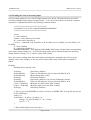
Here you get acquainted with the main parts of the board. Note the names used on the board might
differ from the names used below to describe them. For the actual names check the MOD-IO board
itself.
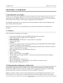
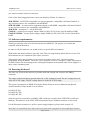
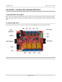
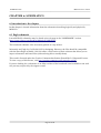
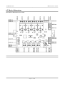
3.1 Layout (top view)
The picture below shows the top side of the board and highlights the most important parts:
Page 16 of 30
OLIMEX© 2015
MOD-IO user's manual
CHAPTER 4: THE ATMEGA16A MICROCONTROLLER
4. Introduction to the chapter
In this chapter is located the information about the heart of OLinuXino – its microcontroller. The
information is a modified version of the datasheet provided by its manufacturers.
4.1 The processor
The features of the A10 processor according to the manufacturer Allwinner:
MOD-IO uses an 8-bit AVR Microcontroller with 16K Bytes In-System Programmable Flash, with
these features:
High-performance, Low-power AVR® 8-bit Microcontroller
Advanced RISC Architecture
131 Powerful Instructions – Most Single-clock Cycle Execution
32×8 General Purpose Working Registers
Fully Static Operation
Up to 16 MIPS Throughput at 16 MHz
On-chip 2-cycle Multiplier
High Endurance Non-volatile Memory segments
16K Bytes of In-System Self-programmable Flash program memory
512 Bytes EEPROM
1K Byte Internal SRAM
Write/Erase Cycles: 10,000 Flash/100,000 EEPROM
Data retention: 20 years at 85°C/100 years at 25°C
Optional Boot Code Section with Independent Lock Bits
In-System Programming by On-chip Boot Program
True Read-While-Write Operation
Programming Lock for Software Security
JTAG (IEEE std. 1149.1 Compliant) Interface
Boundary-scan Capabilities According to the JTAG Standard
Extensive On-chip Debug Support
Programming of Flash, EEPROM, Fuses, and Lock Bits through the JTAG Interface
Peripheral Features
Two 8-bit Timer/Counters with Separate Prescalers and Compare Modes
One 16-bit Timer/Counter with Separate Prescalers, Compare Mode, and Capture Mode
Real Time Counter with Separate Oscillator
Four PWM Channels
8-channel, 10-bit ADC
8 Single-ended Channels
7 Differential Channels in TQFP Package Only
2 Differential Channels with Programmable Gain at 1x, 10x, or 200x
Byte-oriented Two-wire Serial Interface
Programmable Serial USART
Master/Slave SPI Serial Interface
Programmable Watchdog Timer with Separate On-chip Oscillator
Page 17 of 30
OLIMEX© 2015
MOD-IO user's manual
On-chip Analog Comparator
Special Microcontroller Features
Power-on Reset and Programmable Brown-out Detection
Internal Calibrated RC Oscillator
External and Internal Interrupt Sources
Six Sleep Modes: Idle, ADC Noise Reduction, Power-save, Power-down, Standby and
Extended Standby
I/O and Packages
32 Programmable I/O Lines
Operating Voltages
2.7 – 5.5V
Speed Grades
0 – 8 MHz
Power Consumption @ 1 MHz, 3V, and 25⋅C
Active: 1.1 mA
Idle Mode: 0.35 mA
Power-down Mode: < 1 µA
More information can be found on Atmel's web site at the following web-address:
http://www.atmel.com/images/doc8154.pdf
Page 18 of 30
OLIMEX© 2015
MOD-IO user's manual
CHAPTER 5: CONNECTORS AND PINOUT
5. Introduction to the chapter
In this chapter are presented the connectors that can be found on the board all together with their
pinout and notes about them. Jumpers functions are described. Notes and info on specific
peripherals are presented. Notes regarding the interfaces are given.
5.1 Communication with MOD-IO
There are several ways for communication with MOD-IO and its main microcontroller
ATMEGA16A.
The three typical communication routines are: via I2C by utilizing the default firmware; via ISP
with a compatible programmer tool and writing own code; via JTAG with a compatible debugger
tool and writing own code.
The communication with the board's default firmware is performed typically via the I2C line that
might be found on the UEXT connector. For more information on how the default firmware might
be accessed please refer to chapter 2.6.
Page 19 of 30
OLIMEX© 2015
MOD-IO user's manual
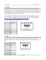
5.2 AVRISP
The AVRISP connector is used to program the board. You can plug a standard ISP programmer
(which has a 10-pin connector) to it. Make sure your programmer supports the programming of
ATMEGA16A microcontroller. Almost any ISP programmer would be capable of programming the
chip. OLIMEX sells at least two programmers suitable for the board – they are named AVR-ISP500
and AVR-ISP-MK2 – both working fine with all versions of Atmel Studio and also open source
tools like AVRDude. Both have 10-pin ISP connector.
If your programmer has only 6 pin interface you can still use it for programming as long as you
make a small adapter or set jumper wires properly. Tables with proper connections required to
convert 6-pin ISP to 10-pin ISP are seasy to be found. You can also use our adapter AVR-ICSP:
https://www.olimex.com/Products/AVR/Programmers/AVR-ICSP/
The pinout of AVRISP might be found below:
Pin #
Signal name
1
MOSI
2
3.3V
3
NC
4
GND
5
RST
6
GND
7
SCK
8
GND
9
MISO
10
GND
5.3 JTAG
The JTAG connector is used to program the board. You can plug a standard ISP programmer (which
has a 10-pin connector) into it. Make sure your programmer supports the programming of
ATMEGA16A microcontroller. Almost any ISP programmer would be capable of programming the
chip.
Pin #
Signal Name
1
TCK
2
GND
3
TDO
4
3.3V
5
TMS
6
RST
7
3.3V
8
NC
9
TDI
10
GND
Page 20 of 30
OLIMEX© 2015
MOD-IO user's manual
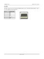
5.4 EXT
The EXT connector has 4 pins from the ATMEGA16A's port D – PD4, PD5, PD6 and PD7; it has a
VCC and GND for easier access also.
Pin #
Signal Name
1
PD7
2
PD6
3
PD5
4
PD4
5
3.3V
6
GND
Page 21 of 30
OLIMEX© 2015
MOD-IO user's manual
5.5 UEXT_MALE
This connector is usually used for the I2C communication with the host board (the more powerful
board that uses the MOD-IO). Additional 10-pin female-female cables might be purchased from our
web-shop: https://www.olimex.com/Products/Components/Cables/CABLE-IDC10-15cm/
Pin #
Signal Name
1
NC
2
GND
3
RXD
4
TXD
5
SCL
6
SDA
7
MISO
8
MOSI
9
SCK
10
#SS
5.6 UEXT_FEMALE
The UEXT female connector is not typical for the OLIMEX boards. It allows multiple MOD-IO
boards to be connected to each other even without the need of a cable! Just plug the
UEXT_FEMALE of board 1 to the UEXT_MALE of board 2. You can have as many boards as you
want as long as each of them has unique identifier for the I2C communication.
Pin #
Signal Name
1
NC
2
GND
3
RXD
4
TXD
5
SCL
6
SDA
7
MISO
8
MOSI
9
SCK
10
#SS
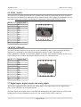
5.7 Digital inputs, digital outputs and analog inputs
The board is equipped with connectors for analog input. It has optocouplers on the digital input
lines. It also has relays on the digital outputs.
All of the inputs and outputs can be controlled and monitored by the default firmware of the board
sending and receiving commands over the I2C line located on the UEXT connector.
Page 22 of 30
OLIMEX© 2015
MOD-IO user's manual
5.7.1 IN1, IN2 IN3, IN4 – digital inputs
Pin #
Signal
1
-
2
+
IN1 connected to (T0)PB0 – signal I4
IN2 connected to (T1)PB1 – signal I3
IN3 connected to (AIN0/INT2)PB2 – signal I2
IN4 connected to (INT1)PD3 – signal I1
The digital inputs high position would typically mean input signal is in the (3-24)V range.
The digital inputs low position would typically mean input signal in (0-1)V range.
5.7.2 OUT1, OUT2, OUT3, OUT4 – digital outputs
The digital outputs are controlled by the big orange relays on the top of the board.
OUT1 connected to (ADC3)PA3 – signal name O4
OUT2 connected to (ADC2)PA2 – signal name O3
OUT3 connected to (ADC1)PA1 – signal name O2
OUT4 connected to (ADC0)PA0 – signal name O1
5.7.3 AIN-1 and AIN-2 – analog inputs
The analog inputs are located on two connectors that are placed next to each other. The connectors
are named AIN-1 and AIN-2.
AIN-1
Pin #
Signal Name
Connected to
1
3.3V
VCC
2
AN1
(ADC7)PA7
3
AN2
(ADC6)PA6
Pin #
Signal Name
Connected to
1
AN3
(ADC5)PA5
2
AN4
(ADC4)PA4
3
AGND
Analog GND
AIN-2
Page 23 of 30
OLIMEX© 2015
MOD-IO user's manual
5.8 PWR jack
The power jack used is the typical 2.5mm one used by Olimex in most of our products. You should
provide 5 volts direct current and the required current may vary depending on the peripherals
connected to the board. The power supply you use should be capable of providing at least 1A of
current.
Pin #
Signal Name
1
Power Input
2
GND
More info about the power supply can be found in chapter 5 of this manual.
5.9 Additional hardware components
The components and circuits below are mounted on MOD-IO but are not discussed thoroughly in
the document above. They are listed here for completeness:
PWR_LED – shows whether the board is powered; turns on upon powering the board
STAT LED – general purpose LED, that can be programmed by the user; blinks upon powering the
board; connected via R11 (330 Ohm) to Atmega16l pin 43 ((AIN1)PB3).
Status LED (red) with name LED1 – visualize input (IN1) state.
Status LED (red) with name LED2 – visualize input (IN2) state.
Status LED (red) with name LED3 – visualize input (IN3) state.
Status LED (red) with name LED4 – visualize input (IN4) state.
Status LED (green) with name O1 – visualize relay (REL1) state.
Status LED (green) with name O2 – visualize relay (REL2) state.
Status LED (green) with name O3 – visualize relay (REL3) state.
Status LED (green) with name O4 – visualize relay (REL4) state.
RST button – used to reset the board connected to Atmega16A pin 4 (RESET).
BUT button – general purpose button, that can be programmed by the user; connected to
Atmega16A pin 11 ((INT0)PD2).
Quartz crystal Q1 – 8 MHz, connected to ATmega16A pin 7 (XTAL2) and pin 8 (XTAL1).
Quartz crystal Q2 – 32.768kHz (real-time clock) quartz crystal, connected to ATmega16A pin 25
((TOSC1)PC6) and pin 26 ((TOSC2)PC7).
Reset circuit – MOD-IO reset circuit includes a reset chip MCP130T (U2), AVRISP connector pin
5, JTAG connector pin 6, Atmega16A pin 4 (RESET), R9 (100R), R10 (10k), C10 (100nF) and a
RST button.
Page 24 of 30
OLIMEX© 2015
MOD-IO user's manual
CHAPTER 6: SCHEMATICS
6. Introduction to the chapter
In this chapter is located information about the schematics describing logically and physically
MOD-IO.
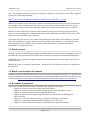
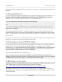
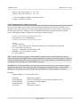
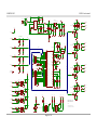
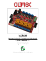
6.1 Eagle schematic
Latest MOD-IO schematics may be found at its web-page in the “HARDWARE” section:
https://www.olimex.com/Products/Modules/IO/MOD-IO/
The board and schematic files are usually packed in a zip archive.
We mostly use Eagle by Cad Soft 4.16r2 for designing. However, the files should be compatible
with the latest Eagle available. Cad Soft offers a trial version of their software that allows you to
inspect schematics and board files (without being able to modify them).
This work is licensed under the Creative Commons Attribution-ShareAlike 3.0 Unported License.
To view a copy of this license, visit http://creativecommons.org/licenses/by-sa/3.0/.
If you are looking for a schematic of an older revision of the board and it isn't available at our web
site you may request it by the support e-mail.
Page 25 of 30
OLIMEX© 2015
MOD-IO user's manual
G1
DB104(SMD)
4
YDJ-1134
8-30 VDC
2
SW
1
RT
IN
BD9001FSO-8
100n
R2
D1
1N5819(smd)
R3
110k
C5
AIN-1-1
ADJ/GND
R4
8.2K
C6
10n
240R/1%
C7
R6
100n
390R/1%
C8
C9
100n
R5
R19
AIN-1-2
Fmax=50kHz
100R
AN1
C20
NA
33nF
AIN-1-3
TB2/3.5mm
R22
C21
NA
33nF
AN[1..4]
AN3
100R
R24
C22
NA
33nF
2
4
6
8
10
1
3
5
7
9
C23
R26
3.3V
JTAG
AIN-2-3
3.3V
TB2/3.5mm
2
4
RST 6
8
10
IN4-1
IN3-1
+
IN2-1
IN1-1
red
LED3
330R
D4
1N4148/SMD
26
25
24
23
22
21
20
19
I1
BUT
TXD
RXD
16
15
14
13
12
11
10
9
-
EXT
WF6S
U5
1
4
2
3
I2
4
2
3
(TOSC2)PC7
(TOSC1)PC6
PC5(TDI)
PC4(TDO)
PC3(TMS)
PC2(TCK)
PC1(SDA)
PC0(SCL)
330R
D2
1N4148/SMD
4
2
3
H11A817SMD
3.3V
AVCC
28
AGND
1K
R39
10K
C15
100n
3.3V
D7
1N4148/SMD
VCC
O3
38
VCC2
4.7K
OUT2-3
OUT2-2
OUT2-1
17
VCC1
R41
T2
BC817
1K
R42
10K
(OC2)PD7
(ICP)PD6
(OC1A)PD5
(OC1B)PD4
(INT1)PD3
(INT0)PD2
(TXD)PD1
(RXD)PD0
6
GND
C16
18
GND1
C17
C18
100n 100n
100n
39
GND2
ATMEGA16L
3.3V
3.3V
R12
4.7K
R13
R34
REL2
R43
1K
5
D6
1N4148/SMD
3.3V
3.3V
3.3V
R14
R15
R16
R17
R18
NA
4.7K
NA
4.7K
4.7K
BUT
UEXT_MALE
100R
C19
BUT
100n
T1107A(6x3.8x2.5mm)
RXD
SCL
MISO
SCK
1
3
5
7
9
2
4
6
8
10
TXD
SDA
MOSI
#SS
BH10S
Page 26 of 30
UEXT_FEMALE
RXD
SCL
MISO
SCK
1
3
5
7
9
2
4
6
8
10
TXD
SDA
MOSI
#SS
IDC10S/PCB
R44
1K
R45
10K
3.3V
R32
4.7K
I4
green
O2
REL2
RAS-05-15
green
O1
REL1
RAS-05-15
REL1
R46
1K
OUT1-3
OUT1-2
OUT1-1
I3
I3
T3
BC817
MCP130T
100n
27
OUT3-2
3.3V
C14
29
AREF
R38
NA
O4
U3
1
O2
O[1..4]
I4
red
LED1
8
XTAL1
C11
C12
33p
C13
33p
Q1
OUT3-3
OUT3-1
VCC 2
GND
7
REL3
R40
1K
U2
4.7K
U4
1
1 RESET
8MHz/20pF
green
O3
REL3
RAS-05-15
R10
RST
4
XTAL2
(SCK)PB7
(MISO)PB6
(MOSI)PB5
(SS)PB4
(AIN1)PB3
(AIN0/INT2)PB2
(T1)PB1
(T0)PB0
R30
H11A817SMD
-
+
4.7K
3
TDI
1
2
3
4
5
6
R28
H11A817SMD
red
LED2
330R
D3
1N4148/SMD
R33
IN1-2
I1
H11A817SMD
-
+
4
100n
RESET
(ADC7)PA7
(ADC6)PA6
(ADC5)PA5
(ADC4)PA4
(ADC3)PA3
(ADC2)PA2
(ADC1)PA1
(ADC0)PA0
I2
R31
IN2-2
U6
1
2
R29
IN3-2
red
LED4
330R
D5
1N4148/SMD
T1107A(6x3.8x2.5mm)
D8
1N4148/SMD
3.3V
+5V
TDI
TDO
TMS
TCK
SDA
SCL
GND
3.3V
R27
+
Q2
32768Hz/6pF
TCK
TDO
TMS
1
3
5
7
9
I1
IN4-2
330R
STAT
yellow
3.3V
33nF
NA
RST
C10
+5V
3
2
1
44
43
42
41
40
RST
R11
AN4
100R
T4
BC817
R36
10K
O[1..4]
SCK
MISO
MOSI
#SS
LED
I2
I3
I4
AVRISP
BH10S
AIN-2-2
R35
1K
GND
3
30
31
32
33
34
35
36
37
3.3V
AIN-2-1
OUT4-1
O1
1K
10K
AN1
AN2
AN3
AN4
O4
O3
O2
O1
O[1..4]
R23
OUT4-3
OUT4-2
R8
R9
AN2
100R
REL4
R37
1K
2K
100R
R21
green
O4
REL4
RAS-05-15
+5V
R20
D9
1N4148/SMD
PWR_LED
red
R7
47uF/6.3V
0R
4n7
OUT
+
C3
GND
3.3V
VR2(3.3V)
LM1117IMPX-ADJ
100uH/SW68
6
+
150k
INV
FB
+5V
L1
7
3
C1
EN
220u/10V/tant
R1
3.3V
VIN
N.C.
C4
220uF/35V
1uF/50v
5
+5V
VR1(5V)
8
+
C2
PWR_J
MOD-IO
Rev. A
COPYRIGHT(C), 2009
http://www.olimex.com/dev
T1
BC817
OLIMEX© 2015
MOD-IO user's manual
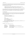
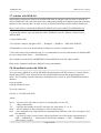
6.2 Physical dimensions
Note that all dimensions are in mm.
Page 27 of 30
OLIMEX© 2015
MOD-IO user's manual
CHAPTER 7: REVISION HISTORY AND SUPPORT
7. Introduction to the chapter
In this chapter you will find the current and the previous version of the document you are reading.
Also the web-page for your device is listed. Be sure to check it after a purchase for the latest
available updates and examples.
7.1 Document revision
Document revision Changes
Modified page
A, 26.06.14
Initial manual release
All
B, 14.05.15
Fixed typo in commands required by i2ctools; added instruction for usage in
Arduino; improved the section borders
14, 19-30
for better readability; improved the
numbering of the chapters
7.2 Board revision
Remember to check the schematics and the board design files to compare the differences.
Board revision
A
Notable changes
Initial release of the board
Page 28 of 30
OLIMEX© 2015
MOD-IO user's manual
8.3 Useful web links and purchase codes
The web page you can visit for more information about your device are:
https://www.olimex.com/Products/Modules/IO/MOD-IO/open-source-hardware
Wiki article of the board: https://www.olimex.com/wiki/MOD-IO
A place for general questions, FAQ or friendly talk: https://www.olimex.com/forum/.
You may may join our IRC channel #olimex @ freenode.net (http://webchat.freenode.net/?
channels=olimex).
ORDER CODES:
MOD-IO – the product for which this manual is about
AVR-ISP500 – an STK500-comaptible low-cost programmer, compatible with Atmel Studio 6 or
any previous version; also compatible with AVRDude
AVR-ISP-MK2 – an open-source programmer based on ISP-MKII, compatible with Atmel Studio 6
or any previous version; also compatible with AVRDude
AVR-ICSP – an adapter 6<->10 pin AVR ISP
SY0605E – reliable power supply adapter 50Hz (EU) 5V/1A for A10-OLinuXino-LIME
SY0605E-CHINA – cheaper power supply adapter 50Hz (EU) 5V/1A for A10-OLinuXino-LIME
How to purchase?
You can purchase directly from our online shop or from any of our distributors. Note that usually it
is faster and cheaper to purchase Olimex products from our distributors. List of confirmed Olimex
LTD distributors and resellers: https://www.olimex.com/Distributors.
Please visit https://www.olimex.com/ for more info.
Page 29 of 30
OLIMEX© 2015
MOD-IO user's manual
8.4 Product support
For product support, hardware information and error reports mail to: [email protected]. All
document or hardware feedback is welcome. Note that we are primarily a hardware company and
our software support is limited. Please consider reading the paragraph below about the warranty of
Olimex products.
All goods are checked before they are sent out. In the unlikely event that goods are faulty,
they must be returned, to OLIMEX at the address listed on your order invoice.
OLIMEX will not accept goods that have clearly been used more than the amount needed to
evaluate their functionality.
If the goods are found to be in working condition, and the lack of functionality is a result of
lack of knowledge on the customers part, no refund will be made, but the goods will be returned
to the user at their expense.
All returns must be authorized by an RMA Number. Email [email protected] for authorization
number before shipping back any merchandise. Please include your name, phone number and order
number in your email request.
Returns for any unaffected development board, programmer, tools, and cables permitted within 7
days from the date of receipt of merchandise. After such time, all sales are considered final.
Returns of incorrect ordered items are allowed subject to a 10% restocking fee. What is
unaffected? If you hooked it to power, you affected it. To be clear, this includes items that
have been soldered to, or have had their firmware changed. Because of the nature of the
products we deal with (prototyping electronic tools) we cannot allow returns of items that have
been programmed, powered up, or otherwise changed post shipment from our warehouse.
All returned merchandise must be in its original mint and clean condition. Returns on damaged,
scratched, programmed, burnt, or otherwise 'played with' merchandise will not be accepted.
All returns must include all the factory accessories which come with the item. This includes
any In-Circuit-Serial-Programming cables, anti-static packing, boxes, etc.
With your return, enclose your PO#. Also include a brief letter of explanation of why the
merchandise is being returned and state your request for either a refund or an exchange.
Include the authorization number on this letter, and on the outside of the shipping box.
Please note: It is your responsibility to ensure that returned goods reach us. Please use a
reliable form of shipping. If we do not receive your package we will not be held liable.
Shipping and handling charges are not refundable. We are not responsible for any shipping
charges of merchandise being returned to us or returning working items to you.
The full text might be found at https://www.olimex.com/wiki/GTC#Warranty for future reference.
Page 30 of 30