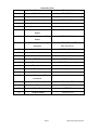
1
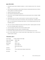
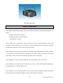
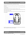
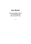
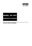
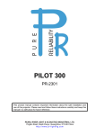
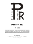
LAZER 150G
PR-5030A
This product manual contains important information about the safe installation and
use of this projector. Please read and follow these instructions carefully and keep this
manual in a safe place for future reference.
PR LIGHTING LTD.
Yingbin Road, Dashi Panyu, Guangzhou, 511430 China
h t t p : / / ww w. p r - l i g h t i n g . c o m
INDEX
MAIN FEATURES
SAFETY WARNING
SAFETY PROTECTION FUNCTIONS
SAFE USAGE OF THE PROJECTOR
INSTALLING THE PROJECTOR
POWER SUPPLY – MAINS
OPERATION
XLR CONNECTORS AND TERMINATOR
DMX512 CONTROL
DMX CONTROL CHANNEL FUNCTIONS
OPERATIONS FOR DATA REFRESH
MAINTENANCE
ELECTRICAL DIAGRAM
NOTICE
3
4
5
6
7
7
8
9
10
11
17
17
18
21
Please note that as part of our ongoing commitment to continuous product development, specifications are subject to change
without notice. Whilst every care is taken in the preparation of this manual, we reserve the right to change specifications in the
course of product improvement. The publishers cannot be held responsible for the accuracy of the information herein, or any
consequence arising from them.
Every apparatus is tested completely and packed properly by the manufacturer. Please make sure the packing and / or the
apparatus is in good condition before your installation and use. Should there be any damage caused by transportation, consult
your dealer and do not use the apparatus. Any damage caused by improper use will not be assumed by the manufacturer and /
or dealer.
ACCESSORIES
THESE ITEMS ARE PACKED TOGETHER WITH THE PROJECTOR
Power-cord (1 PCS)
XLR cable with 3-pin plug and socket (1 PCS)
Cable of data refreshes (1 PCS)
CD included this manual (1 PCS)
Laser key (2 PCS)
Urgency laser safety switch + Connector (1 set)
INTRODUCTION
Thank you for purchasing our product LAZER 150, PR-5030A series.
This product manual contains important information about the safe installation and use of this projector.
Please read and follow these instructions carefully and keep this manual in a safe place for future
reference
The LAZER 150 is an innovative projector with an elegant housing, which is made from high intensity
and heat-resistant complex plastic. LAZER 150 complies with CE norms and standards and uses
international protocol DMX 512. The LAZER 150 uses 16 DMX channels. Through DMX 512 controller,
you can select the pictures and their movement changing methods, so you can get charming and
dreamful effect of the various laser pictures. The projector has 3 group of sound activation demo so
makes light and sound uniformity come true. You can get impact effect using the music together. The
unit has reliable safety equipments. Once the errors occur, the unit will be cut off automatically. It is
suitable for application in TV station, discotheque, singing and dancing stage, nightclub, bar, press
conference, exhibition, etc.
The projector uses green solid laser lamp for light source. This series also has PR-5031, PR-5032,
PR-5033, and PR-5034 and so on according to the differences of the power consumption and colour
of their light source. All of the product manuals in the PR-5030A series are same except the
differences of the power consumption and colour.
2/21
Laser 100 manual_en.doc
MAIN FEATURES:
1. Professional optical system dustproof technique, so need not periodic clean even if long time
usage.
2. Uses international standard high speed vibratile lens whose scanning speed above 30K, make the
scanning pattern more steady and exquisite.
3. Adopts the latest laser lamp of DPSS.
4. Uses international standard DMX 512 protocol.
5. Laser pictures, picture changing method and picture movement speed can be controlled via DMX
512 controller.
6. Adopts large memory of FLASH to save the pictures. The memory capacity can up to 8Mbit.
7. There are 256 built-in basic pictures and characters, 256 pre-programmed “combination picture
effect”, up to 300,000 kinds of actual light beam effects, 10 set of beautiful animation and 32 user
refreshable graphics.
8. Users can convert the standard ILDA format into the laser pictures, compile program and refresh
the 32 user refreshable graphics inside the unit.
9. The 12-bit resolution of the laser picture makes the pictures clearer.
10. Adopts BLANKING technology to produce verisimilitude images.
11. Has multi-laser safety protection function and can cut off automatically if any error occurs.
12. Has 3 sound activation demo to achieve impact effect, single projector can run under sound
activation without controller.
TECHNICAL DATA
Power supply:
90-220V AC 50Hz, wide voltage
Power consumption:
100W / 220V
Output power:
150mW
Beam length:
532nm, Green
Interface:
Control: DMX 512
Refresh data: RS-232
Channels:
16
Dimensions:
411mm LONG x 261mm WIDE x 150mm HIGH
Net weight:
16kg
3/21
Laser 100 manual_en.doc
PR-5030A OUTLOOK
SAFETY WARNING
The LAZER 150 PR-5030A belongs to the CLASS III-B laser product, the laser lamp parameter is as
follows:
Maximum output power:150 mW
Beam length: 532 nm, green therefore
Light spot size: <1.2mm
Note of Safety Use 1: because the energy of this kind of laser is strong enough to result in the
permanence injury to persons’ eyes, must avoid see the laser beam directly in use process, especially
the laser beam stops at a spot can cause eye burns seriously.
Note of Safety Use 2: inside of the projector has automatic laser safety protection circuitry. However,
for your safety, it is recommended that install the “Laser urgency switch” in place you can control
conveniently, so that you can turn off the laser manually in case of emergency.
Note of Safety Use 3: for your safety, please do not run the projector when cover is open.
Note of Safety Use 4: please take off the laser key if non-use, in case of other people unfamiliar with
the projector turn it on and then lead to harm.
Note of Safety Use 5: the safety standard in every country and area is different. Please contact local
laser official to know correlative regulations before actual usage of the projector.
4/21
Laser 100 manual_en.doc
SAFETY PROTECTION FUNCTIONS
The laser safety protection measures of this product LAZER 150 PR-5030A are implemented
according to the relative European items. These measures are as below:
▲ the cover open protection: open the plastic shell if there is current flows, the laser will be cut off
automatically.
▲ laser key switch: the laser can be switch on when key is under on circumstance; the key cannot pull
out at the same time.
▲ external urgent and safe switch: switch off the laser manually if error occurs.
▲ laser indication device: there are laser indication devices at the side of key switch and on the socket,
used to indicate “the laser is ready".
▲ laser safety marks: there are marks on the head of the unit at several places comply with the
Europe standard.
LASER RADI ATI ON CALSS 3B
I F COVER I S OPENED AND
I NTERLOCK DEFEATED
AVOI D DI RECT EXPOSURE TO BEAM
▲the laser safety protection panel: if the laser beam scans in a small spot may have safety-hidden
trouble. The panel will be closed within 25 ms compulsorily.
SAFE USAGE OF THE PROJECTOR
KEY WORD: LASER SAFETY USAGE
5/21
Laser 100 manual_en.doc
The following points are important for safety as well as for the smooth
installation and performance of the unit
When unpacking and before disposing of the carton, check there is no transportation damage before
using the projector. Keep the carton well for future possible transportation. Should there be any
damage caused by transportation, consult your dealer and do not use the apparatus.
The projector is for Indoor use only, IP20. Use only in dry locations. Keep this device away from rain
and moisture, excessive heat, humidity and dust. Do not allow contact with water or any other fluids, or
metallic objects.
The projector is not designed or intended to be mounted directly on to inflammable surfaces.
The projector is only intended for installation, operation and maintenance by qualified personnel.
The projector must be installed in a location with adequate ventilation, at least 50cm from adjacent
surfaces. Be sure that no ventilation slots are blocked.
Do not project the beam onto inflammable surfaces, minimum distance is 3m.
3m
Avoid direct exposure to the light from the lamp. The light is harmful to the eye.
Do not attempt to dismantle and/or modify the projector in any way.
Electrical connection must only be carried out by qualified personnel.
Before installation, ensure that the voltage and frequency of power supply match the power
requirements of the projector.
It is essential that each projector is correctly earthed and that electrical installation conforms to all
relevant standards.
Do not connect this device to any dimmer pack.
Make sure that the power-cord is never crimped or damaged by sharp edges. Never let the powercord come into contact with other cables. Only handle the power-cord by the plug. Never pull out the
plug by tugging the power-cord.
The projector should always be installed with a secondary safety fixing. A safety cord is supplied for
this and it should be attached as shown in “installing the projector” section.
There are no user serviceable parts inside the projector. Please do not open the housing and never
operate the projector with the covers removed.
Always disconnect from the mains, when the device is not in use or before
cleaning it or before attempting any maintenance work.
If you have any questions, do not hesitate to consult your dealer or manufacturer.
6/21
Laser 100 manual_en.doc
INSTALLING THE PROJECTOR
Always ensure that the projector is firmly anchored to avoid vibration and slipping whilst functioning.
Always ensure that the structure to which you are attaching the projector is secure and is able to
support a weight of LAZER 150. For safety, the projector should have a secondary fixing with a safety
chain through the holes on the underside of the unit.
WARNING: The projector should NEVER be lifted or carried by the yoke.
POWER SUPPLY - MAINS
Use the plug provided to connect the mains power to the projector paying attention to the voltage and
frequency marked on the panel of the projector. It is recommended that each projector be supplied
separately so that they may be individually switched on and off.
IMPORTANT
It is essential that each projector is correctly earthed; otherwise, hardware inside the projector may
cause unexpected damage.
7/21
Laser 100 manual_en.doc
OPERATION
The unit uses standard DMX 512 controller. With the
touch-switches and the digital display screen, DMX start
address can be easily set and the various setup options
may be configured.
The display shows the DMX start address after the
projector is switched on (if you have already set the
DMX start address and saved it, the screen will display
the last setting).
TO SET THE DMX START ADDRESS
Press the UP or DOWN buttons and the display will show the DMX start address.
Confirm your choice by pressing the ENTER button, this will save and set the DMX start address.
The display will show the latest setting each time the projector is powered up.
To control the projector with a DMX controller the DMX start address must be set.
Ensure that none of the Stand-Alone options is set or they will interfere with correct DMX operation.
SETUP OPTIONS - PROJECTOR CONFIGURATION
To browse through the various Setup Options, press the FUNC button consecutively. There are 11
Option codes (1~B), and each code has a specific function. The functions provided are listed in the
following table.
SETUP OPTIONS
CODE
1
2
3
4
5
CHOICE
FUNCTION
N
Y
N
Y
1
2
3
N
Y
N
No pan mirror
Pan mirror
No tilt mirror
Tilt mirror
Run sound activation demo 1
Run sound activation demo 2
Run sound activation demo 3
Stop sound activation demo
Self test enable
Self test disable
Without DMX512, built-in DEMO program enable
Connect DMX512, Run sound activation demo 1, 2,
3, and built-in DEMO program according to music
Built-in DEMO program disable
Not used
Not used
Not used
Not used
Not used
Not used
Y
N
6
7
8
9
A
B
When under functional operation, the display format of the digital display screen is:
8/21
Laser 100 manual_en.doc
Once you have selected the desired operation code, press the key UP or DOWN to select “y” (means
ON) or “no “(means OFF). N = NO, Y = YES.
Press the key ENTER to save the selected function and configuration. If the display is showing “y”,
then the setting has been enabled. In the same way, if it was showing “n” when you pressed ENTER
the option has been disabled. The Red LED will flash during this operation.
During function set operation, Green LED will flash one time when press ENTER to indicate the set is
valid. The Red LED will be lit when DMX512 signal is normal.
Note:
1. The codes 3, 4 and 5 should be set “no” When operation.
2. When under sound activation, can use controller to adjust or set 3-Y condition.
3. When use DMX512 controller, codes 4, 5 and 6 should be set “no”.
4. Adjust 1-Y and 2-Y to select suitable display direction according to the actual installation direction.
XLR CONNECTORS AND TERMINATOR
XLR CONNECTORS
Connection between controller and projector and between one projector and another must be made
with 2 core screened cable, with each core having at least a 0.5mm diameter. Connection to and from
the projector is via cannon 3-pin XLR plugs and sockets which are included with the projector. The
XLRs are connected as shown in the figure above.
Note: care should be taken to ensure that none of the connections touches the body of the plug or
each other. The body of the plug is not connected in any way. The LAZER 150 accepts digital control
signals in standard DMX512 (1990) format.
5-PIN AND 3-PIN CONVERSION
LAZER 150 uses 3-pin XLR plug / socket. If your controller uses 5-pin XLR plug / socket, you should
convert 5-pin plug / socket into 3-pin socket / plug as shown below.
9/21
Laser 100 manual_en.doc
DMX TERMINATOR
In the Controller mode or Master/Slave mode, the DMX output has to be connected with a DMX
terminator at the last fixture in the chain. This prevents electrical noise from disturbing and corrupting
the DMX control signals.
The DMX terminator is simply an XLR connector with a 120Ω (ohm) resistor connected across pins 2
and 3, which is then plugged into the output socket on the last projector in the chain. The connections
are illustrated below.
DMX512 CONTROL
Each LAZER 150 must be given a DMX start address so that the correct projector responds to the
correct control signals. This DMX start address is the channel number from which the projector starts
to “listen” to the digital control information being sent out from the controller. The LAZER 150 has 16
channels, so set the No. 1 projector’s address 001, No. 2 projector’s address 017, No. 3 projector’s
address 033, No. 4 projector’s address 049, and so on.
Certainly, you may use formulation: address = channels x (projector No. –1) +1
For example, for the No. 5 projector’s start address, you should calculate according to formulation: 16
x (5 – 1) +1 =65, so you set the No. 5 projector start address 065. (How to set DMX start address
please refer to “Operation” section.)
Connect the controller’s output to the first fixture’s input, and connect the first fixture’s output to the
second fixture’s input. The rest may be deduced by analogy. Eventually connect the last fixture’s
output to a DMX terminator as shown in the figure below.
10/21
Laser 100 manual_en.doc
DMX CONTROL CHANNEL FUNCTIONS
The LAZER 150 uses 16 DMX channels. They are listed in the following table.
CHANNEL
DMX VALUE
1
Unit ON/OFF
0-37
38-74
75-110
111-147
148-184
185-221
222-255
DESCRIPTION
Unit OFF
Unit ON, animation
Unit ON, geometric picture
Unit ON, effect
Unit ON, sound activation 1
Unit ON, sound activation 2
Unit ON, sound activation 3
Term explanation:
Animation: a program made by a group of constant pattern.
Geometric picture: static picture, users can edit moving effect via DMX512 controller.
Effect: pictures have had movement parameters, users cannot edit.
The following channels are only for channel 1 value 64-127, animation.
CHANNEL
2
Animation
Selection
DMX VALUE
0-25
26-51
51-76
76-102
102-127
127-153
153-178
178-204
204-229
229-255
DESCRIPTION
Animation 1
Animation 2
Animation 3
Animation 4
Animation 5
Animation 6
Animation 7
Animation 8
Animation 9
Animation 10
Not used
3
4
Animation movement
5
X Range adjust
0-25
26-51
52-77
78-103
104-129
130-155
156-181
182-207
208-233
234-255
0-15
16-31
32-47
48-63
64-79
80-95
96-111
112-127
128-143
144-159
160-175
176-191
192-207
208-223
224-239
240-255
Animation movement 1 (fastest)
Animation movement 2
Animation movement 3
Animation movement 4
Animation movement 5
Animation movement 6
Animation movement 7
Animation movement 8
Animation movement 9
Animation movement 10 (slowest)
Full range 1/16
Full range 2/16
Full range 3/16
Full range 4/16
Full range 5/16
Full range 6/16
Full range 7/16
Full range 8/16
Full range 9/16
Full range 10/16
Full range 11/16
Full range 12/16
Full range13/16
Full range14/16
Full range15/16
Full range 100%
11/21
Laser 100 manual_en.doc
6
Y Range adjust
0-15
16-31
32-47
48-63
64-79
80-95
96-111
112-127
128-143
144-159
160-175
176-191
192-207
208-223
224-239
240-255
Full range1/16
Full range2/16
Full range3/16
Full range4/16
Full range5/16
Full range6/16
Full range7/16
Full range8/16
Full range9/16
Full range10/16
Full range11/16
Full range12/16
Full range13/16
Full range14/16
Full range15/16
Full range 100%
The following channels are only for channel 1 value 128-191, geometric picture. PR-5030A stores 256
static pictures that divided into 16 groups through channel 2 to choose the group number; every group
is made up of 16 pictures and through channel 3 to choose a picture and through other channel to edit
dynamic effect such as zoom in, rotate, move, write, etc. You can also edit static effect such as corner.
CHANNEL
2
Picture Group
Selection
(16 groups)
3
Picture
Selection
(16 pieces)
4
5
DMX VALUE
0-15
16-31
32-47
48-63
64-79
80-95
96-111
112-127
128-143
144-159
160-175
176-191
192-207
208-223
224-239
240-255
0-15
16-31
32-47
48-63
64-79
80-95
96-111
112-127
128-143
144-159
160-175
176-191
192-207
208-223
224-239
240-255
0-15
DESCRIPTION
Picture group 1
Picture group 2
Picture group 3
Picture group 4
Picture group 5
Picture group 6
Picture group 7
Picture group 8
Picture group 9
Picture group 10
Picture group 11
Picture group 12
Picture group 13
Picture group 14
Picture group 15
Picture group 16
Picture 1
Picture 2
Picture 3
Picture 4
Picture 5
Picture 6
Picture 7
Picture 8
Picture 9
Picture 10
Picture 11
Picture 12
Picture 13
Picture 14
Picture 15
Picture 16
Not used
Full range1/16
12/21
Laser 100 manual_en.doc
X Range Adjust
6
Y Range Adjust
7
Pan Rotation
on Sixteen
8
Tilt Rotation
on Sixteen
16-31
32-47
48-63
64-79
80-95
96-111
112-127
128-143
144-159
160-175
176-191
192-207
208-223
224-239
240-255
0-15
16-31
32-47
48-63
64-79
80-95
96-111
112-127
128-143
144-159
160-175
176-191
192-207
208-223
224-239
240-255
0-15
16-31
32-47
48-63
64-79
80-95
96-111
112-127
128-143
144-159
160-175
176-191
192-207
208-223
224-239
240-255
0-15
16-31
32-47
48-63
64-79
80-95
96-111
112-127
128-143
144-159
160-175
176-191
192-207
208-223
Full range2/16
Full range3/16
Full range4/16
Full range5/16
Full range6/16
Full range7/16
Full range8/16
Full range9/16
Full range10/16
Full range11/16
Full range12/16
Full range13/16
Full range14/16
Full range15/16
Full range 100%
Full range1/16
Full range2/16
Full range3/16
Full range4/16
Full range5/16
Full range6/16
Full range7/16
Full range8/16
Full range9/16
Full range10/16
Full range11/16
Full range12/16
Full range13/16
Full range14/16
Full range15/16
Full range 100%
Pan rotation without direction change
Normal rotation from slow to fast
Pan rotation without direction change
Reverse rotation from slow to fast
Tilt rotation without direction change
Normal rotation from slow to fast
Tilt rotation without direction change
Reverse rotation from slow to fast
13/21
Laser 100 manual_en.doc
9
Z Rotation
on Sixteen
10 Z Initial Angle
11
Zoom In and Out
on Sixteen
12
Pan Movement on 128
13
Tilt Movement on 128
14
Rotation Centre/Write
3
15
Scanning speed
16
Strobe
224-239
240-255
0-15
16-31
32-47
48-63
64-79
80-95
96-111
112-127
128-143
144-159
160-175
176-191
192-207
208-223
224-239
240-255
0-255
0-15
16-31
32-47
48-63
64-79
80-95
96-111
112-127
128-143
144-159
160-175
176-191
192-207
208-223
224-239
240-255
0-127
128-255
0-127
128-255
0-85
86-171
172-255
0-15
16-31
32-47
48-63
64-79
80-95
96-111
112-127
128-143
144-159
160-175
176-191
192-207
208-223
224-239
240-255
0-25
26-51
52-77
Z rotation without direction change
Normal rotation from slow to fast
Z rotation without direction change
Reverse rotation from slow to fast
Anti-clockwise 2.8 degrees when move 2 DMX value
Zoon in and out without change
Zoon in range from small to large
Zoon in and out without change
Zoon out range from small to large
Normal movement increment increases
Reverse movement increment decreases
Normal movement increment increases
Reverse movement increment decreases
Rotate and zoom in/out round the figure centre
Rotate and zoom in/out round the picture centre
Under write circumstance
Scanning speed is 24K
Scanning speed is 23K
Scanning speed is 22K
Scanning speed is 21K
Scanning speed is 20K
Scanning speed is 19K
Scanning speed is 18K
Scanning speed is 17K
Scanning speed is 16K
Scanning speed is 15K
Scanning speed is 14K
Scanning speed is 13K
Scanning speed is 12K
Scanning speed is 11K
Scanning speed is 10K
Scanning speed is 9K
Strobe closed
Strobe 1 (slow)
Strobe 2
14/21
Laser 100 manual_en.doc
78-103
104-129
130-155
156-181
182-207
208-233
234-255
Strobe 3
Strobe 4
Strobe 5
Strobe 6
Strobe 7
Strobe 8
Strobe 9 (fast)
Warning: when use DMX512 to control, some of picture under the edit effect
may result in laser safe protection panel moving but without laser projection.
That is the value of channel 4 or 15 is too large or the value of channel 5 or 6 is
too small. Only need to adjust them to a suitable value, the operation will
become normal.
The following channels are only for channel 1 value 192-255, effect selection. PR-5030A stores 256
pieces of “picture combination effect” which have had movement parameter and divided into 16 groups.
Every group has 16 “picture combination effect”, through channel 2 to choose a group and through
channel 3 to choose a “picture combination effect” in the group. “Picture combination effect” is different
from common picture and it is designed specially and cannot be edited.
CHANNEL
2
Display picture
group selection
3
Display picture
selection
DMX VALUE
0-15
16-31
32-47
48-63
64-79
80-95
96-111
112-127
128-143
144-159
160-175
176-191
192-207
208-223
224-239
240-255
0-15
16-31
32-47
48-63
64-79
80-95
96-111
112-127
128-143
144-159
160-175
176-191
192-207
208-223
224-239
240-255
DESCRIPTION
Display picture group 1
Display picture group 2
Display picture group 3
Display picture group 4
Display picture group 5
Display picture group 6
Display picture group 7
Display picture group 8
Display picture group 9
Display picture group 10
Display picture group 11
Display picture group 12
Display picture group 13
Display picture group 14
Display picture group 15
Display picture group 16
Display picture 1
Display picture 2
Display picture 3
Display picture 4
Display picture 5
Display picture 6
Display picture 7
Display picture 8
Display picture 9
Display picture 10
Display picture 11
Display picture 12
Display picture 13
Display picture 14
Display picture 15
Display picture 16
15/21
Laser 100 manual_en.doc
4
5
X Range Adjust
6
Y Range Adjust
0-15
16-31
32-47
48-63
64-79
80-95
96-111
112-127
128-143
144-159
160-175
176-191
192-207
208-223
224-239
240-255
0-15
16-31
32-47
48-63
64-79
80-95
96-111
112-127
128-143
144-159
160-175
176-191
192-207
208-223
224-239
240-255
Not used
Full range1/16
Full range2/16
Full range3/16
Full range4/16
Full range5/16
Full range6/16
Full range7/16
Full range8/16
Full range9/16
Full range10/16
Full range11/16
Full range12/16
Full range13/16
Full range14/16
Full range15/16
Full range 100%
Full range1/16
Full range2/16
Full range3/16
Full range4/16
Full range5/16
Full range6/16
Full range7/16
Full range8/16
Full range9/16
Full range10/16
Full range11/16
Full range12/16
Full range13/16
Full range14/16
Full range15/16
Full range 100%
16/21
Laser 100 manual_en.doc
OPERATION FOR DATA REFRESH
1. Connect the power cord and cable of data refresh with the unit, and the other end of the cable of
data refresh connecting with a personal computer. Note: The power must be cut off before this
operation.
2. First, turn on the computer power, and then the unit’s power.
3. Don’t run the data refresh program until the red LED near the unit’s screen is blinking. Set the
computer’s interface of COM1 or COM2 according to the cable of data refresh you have connected.
4. Running LASERDANCE 5.0 software, refer to user manual of relative software.
Note: During transmitting the data, the power of the unit cannot be off; otherwise, some components
inside the unit may be damaged! Wait until appear the dialog box for complete transmitting, and then
you turn off the unit.
5. After turning off the unit’s power, pull the data refresh cable out of the unit. Connect the DMX512
cable to the unit for operation.
6. The data refresh cable is made up of DB9/M and DB9/F plugs and 3 core screened cable as shown
below.
MAINTENANCE
Because the unit is a precise device integrated with optics, mechanism and electronics, please pay
attention to the following points when use the unit normally.
1. When use a fog machine, do not eject the fog to the unit directly, minimum distance is 1m. It is
recommended to use a fan to blow strong fog away from the unit, or to use a dry ice machine to
produce the fog.
2. Please use the special cleaning products in cleaning the optics inside the unit. The operation must
be completed by qualified personnel.
3. The scanner drive PCB and scan head inside the unit are used by couple. They must be changed
together. The operation must be completed by qualified personnel.
17/21
Laser 100 manual_en.doc
ELECTRICAL DIAGRAM
a) PR-5030A circuit diagram
b) PR-5030A shape
18/21
Laser 100 manual_en.doc
c) PR-5030A assemblage
d) PR-5030A back nog
19/21
Laser 100 manual_en.doc
Item
Assembly Spec
Name
Description
1
Main-board
ZK4-02 V1.0
2
Reed Switch&Magnet
50V/1A
3
Safe board
LASER-SAFE V1.1
4
X-scanner moto
/
5
Y-scanner moto
/
6
X scanner serve amplifier
SCAN-D1 V4.1A
board
7
Y scanner serve amplifier
SCAN-D1 V4.1A
board
8
Multi-outputs switching
regulator
IN AC85~250V OUT ±
24V/1A,5V/1A
9
Inter-lock board
SAFE-LOCK V1.2
10
Laser power
/
11
laser
532nm,150mw
12
EMI Filter
115/250VAC 1A
13
Potentiometer
14
Panel socket
3 poles
15
Panel plug
3 poles
16
Key Switch
/
17
Laser Emergency Stop
/
10KΩ/0.5W
gain adjust
connector
18
Laser Standby
Red φ3 LED
19
Fan
DC 24V/0.15A
20
Data Port
DB9/M
21
Display board
SZ4-02 V1.0
20/21
Laser 100 manual_en.doc
NOTICE
1. If peripherals or cable is damaged, please purchase it that is PR or LASER Company provided for
change.
2. This software tests normally in the environment of win98, winxp and win2000. We do not provide
the function guarantees if it is not under these operation systems.
3. This software does not include destructive program like wood horse, virus, and back door and so on.
Please use it securely. If user’s system has infected virus, we do not guarantee the program can use
normally.
4. Please keep the projector clean, excessive smoke and bad exterior ambient may degrade use life of
the projector and power attenuation of the lamp.
PR LIGHTING LTD.
Yingbin Road, Dashi, Panyu, Guangzhou, China
Post-Code: 511430
TEL: 020-8478-1888
FAX: 020-8478-6023
P/N: 320030071
Last Revision: 15:06:2006
21/21
Laser 100 manual_en.doc