1
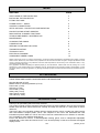
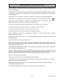
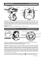
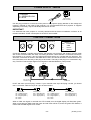
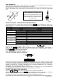
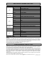
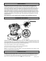
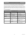
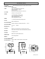
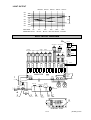
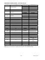
PILOT 300
PR-2301
This product manual contains important information about the safe installation and
use of this projector. Please read and follow these instructions carefully and keep this
manual in a safe place for future reference.
PEARL RIVER LIGHT & ACOUSTICS INDUSTRIAL LTD.
Yingbin Road, Dashi Panyu, Guangzhou, 511430 China
http://www.pr-lighting.com
INDEX
SECTION
PAGE
SAFE USAGE OF THE PROJECTOR
3
INSTALLING THE PROJECTOR
4
FITTING THE LAMP
4
POWER SUPPLY - MAINS
5
CONTROL CONNECTIONS
5
SETUP OPTIONS – PROJECTOR CONFIGURATION
6
PROJECTOR DMX START ADDRESS
6
DMX CONTROL CHANNEL FUNCTIONS
7
STAND-ALONE MODES – MASTER/SLAVE
7
MAINTENANCE
8
CHANGING THE GOBOS
8
LUBRIFICATION
8
KEEPING THE PROJECTOR CLEAN
9
TROUBLESHOOTING
9
TECHNICAL DATA
10
ELECTRICAL DIAGRAM
11
COMPONENT ORDER CODES
12
Please note that as part of our ongoing commitment to continuous product development, specifications are subject to change
without notice. Whilst every care is taken in the preparation of this manual we reserve the right to change specifications in the
course of product improvement. The publishers cannot be held responsible for the accuracy of the information herein, or any
consequence arising from them.
Every apparatus is tested completely and packed properly by the manufacturer. Please make sure the packing and / or the
apparatus is in good condition before your installation and use. Should there be any damage caused by transportation, consult
your dealer and do not use the apparatus. Any damage caused by improper use will not be assumed by the manufacturer and /
or dealer.
ACCESSORIES
THESE ITEMS ARE PACKED TOGETHER WITH THE PROJECTOR
Mounting Bracket (2 PCS)
M8x25 screw for mounting brackets (4 PCS)
Power-cord (1 PCS)
XLR plug (1 PCS)
XLR socket (1 PCS)
Safety cord (1 PCS)
Spare gobos (4 PCS)
This manual (1 PCS)
INTRODUCTION
Thank you for purchasing the PILOT 300, PR-2301.
This product manual contains important information about the safe installation and use of this projector.
Please read and follow these instructions carefully and keep this manual in a safe place for future
reference.
The PILOT 300 is an innovative projector with an elegant housing, which is made from high intensity
and heat–resistant complex plastic. PILOT 300 complies to CE norms and standards and uses
international protocol DMX 512. PILOT 300 can be used as a stand-alone unit or linked to a controller,
so it is suitable for many different applications.
PILOT 300 features 9 colours, 7 interchangeable rotating gobos, and an independent adjustable
strobe/shutter, prism effect and remote focus. It can be setup easily via the touch-switches and digital
display screen.
2/14
pilot300_en.doc
SAFE USAGE OF THE PROJECTOR
When unpacking and before disposing of the carton check there is no transportation damage before
using the projector. Should there be any damage caused by transportation, consult your dealer and do
not use the apparatus.
The projector is for Indoor use only, IP20. Use only in dry locations. Keep this device away from rain
and moisture, excessive heat, humidity and dust. Do not allow contact with water or any other fluids,
or metallic objects.
The projector is only intended for installation, operation and maintenance by qualified personnel.
The projector is not designed or intended to be mounted directly on to inflammable surfaces.
The projector must be installed in a location with adequate ventilation, at least 50cm from
adjacent surfaces. Be sure that no ventilation slots are blocked.
Do not project the beam onto inflammable surfaces, minimum distance is 3m.
3m
Avoid direct exposure to the light from the lamp. The light is harmful to the eye.
Do not attempt to dismantle and/or modify the projector in any way.
Electrical connection must only be carried out by qualified personnel.
Before installation, ensure that the voltage and frequency of power supply match the power
requirements of the projector.
It is essential that each projector is correctly earthed and that electrical installation conforms to all
relevant standards.
Do not connect this device to any dimmer pack.
Make sure that the power-cord is never crimped or damaged by sharp edges. Never let the powercord come into contact with other cables. Only handle the power-cord by the plug. Never pull out the
plug by tugging the power-cord.
The projector should always be installed with a secondary safety fixing. A safety cord is supplied for
this, it should be attached as shown.
The lamp used in this projector is an HTI 300W/DX discharge lamp. After being switched off don’t
attempt to restart the projector until the lamp has cooled, this will require approx 15 minutes. Switching
the lamp on and off at short intervals will reduce the life of both the lamp and the projector.
Never run the projector without a lamp.
Keep the lamp clean. Do not touch the lamp glass with bare hands.
There are no user serviceable parts inside the projector, do not open the housing and never operate
the projector with the covers removed.
Always disconnect from the mains, when the device is not in use or before cleaning it or before
attempting any maintenance work.
If you have any questions, don’t hesitate to consult your dealer or manufacturer.
3/14
pilot300_en.doc
INSTALLING THE PROJECTOR
Pass safety fixing
through these holes
280mm
BRACKET
BRACKET
BRACKET
BRACKET
106mm
The projector should be mounted via its brackets using 2 M12 bolts. The brackets attach to the
underside of the projector with 4 M8x25 bolts provided. Always ensure that the projector is firmly
anchored to avoid vibration and slipping whilst functioning. Always ensure that the structure to which
you are attaching the projector is secure and is able to support a weight of 18Kg for each PILOT 300.
For safety the projector should have a secondary fixing with a safety chain through the holes on the
underside of the unit.
WARNING: The projector should NEVER be lifted or carried by the yoke.
FITTING THE LAMP
ACCESS SCREW
LAMP ADJUSTMENT
BUBBLE
A
LAMP ADJUSTMENT
LAMP
B
ACCESS SCREW
Adjust lamp
position by
turning screws
A, B, and C
LAMP ACCESS HATCH
ACCESS SCREW
LAMP ADJUSTMENT
C
ONLY USE REPLACEMENT
LAMP TYPE: HTI 300W/DX
LAMP ACCESS HATCH
Loosen the 3 access screws at the rear of the projector and pull the lamp access hatch straight out
from the rear of the projector. Insert an HTI 300W/DX lamp in the lamp holder.
Close the lamp access hatch, then tighten the 3 access screws.
NOTE: When fitting the lamp position it with the little bubble vertically (either upwards or downwards)
as shown in the diagram above. Do not position it horizontally. Close the access hatch carefully and
re-tighten the 3 screws. To optimize light output it will be necessary to adjust the lamp alignment to
obtain an even distribution of light within the beam. The three screws (marked A, B, and C) may be
gently turned to center the lamp within the reflector. The projector should be switched on with the
shutter open and the beam focused to do this, it is also advisable to allow the lamp 5 minutes to come
up to full brightness before starting to align it. Note: the three screws will only need a small adjustment
to centre the lamp, do not try to unscrew them completely. Read the rest of this manual and then come
back to this section to align the lamp.
The HTI series are high pressure lamps with external igniters ( ). Care should always be taken when
handling these lamps. Always read the manufacturers "Instructions for use" enclosed with the lamp.
4/14
pilot300_en.doc
POWER SUPPLY - MAINS
L = BROWN
E = GREEN/YELLOW
N = BLUE
FUSE HOLDER
FUSE F6.3A/250V
L E
N
Use the plug provided to connect the mains power to the projector paying attention to the voltage and
frequency marked on the panel of the projector. It is recommended that each projector is supplied
separately so that they may be individually switched on and off.
IMPORTANT
It is essential that each projector is correctly earthed and that electrical installation conforms to all
relevant standards. Power consumption of the PILOT 300 is 480W.
CONTROL CONNECTIONS
DMX OUT
DMX IN
2
1
1
2
3
3
PIN
DMX 512
FUNCTION
1
2
3
GND
DATA DATA +
Connection between controller and projector and between one projector and another must be made
with 2 core screened cable, with each core having at least a 0.5mm diameter. Connection to and from
the projector is via cannon 3 pin XLR plugs and sockets which are included with the projector. The
XLR's are connected as shown in the table above. Note, care should be taken to ensure that none of
the connections touch the body of the plug or each other. The body of the plug is not connected in any
way. The PILOT 300 accepts digital control signals in standard DMX512 (1990) format.
No. 1
DMX IN
No. n
No. 2
DMX OUT
DMX IN
DMX OUT
DMX IN
DMX IN FROM
CONTROLLER
DMX OUT
TERMINATOR
PILOT 300 uses 3-pin XLR plug / socket. If your controller uses 5-pin XLR plug / socket, you should
use a conversion cable from 5-pin to 3-pin as shown bellow.
5 PIN SOCKET
3 PIN PLUG
5 PIN PLUG
3 PIN SOCKET
Pin 1: GND (Screen)
Pin 2: Signal (data -)
Pin 3: Signal (data +)
Pin 4: N/C
Pin 5: N/C
Pin 1: GND (Screen)
Pin 2: Signal (data -)
Pin 3: Signal (data +)
Pin 1: GND (Screen)
Pin 2: Signal (data -)
Pin 3: Signal (data +)
Pin 4: N/C
Pin 5: N/C
Pin 1: GND (Screen)
Pin 2: Signal (data -)
Pin 3: Signal (data +)
When a DMX 512 signal is received the LED located near the digital display will illuminate green.
When not receiving a DMX signal the green and red LEDs will be off, and if the green LED flashes, it
means that the DMX signal is not correct.
5/14
pilot300_en.doc
DMX TERMINATOR
At the last fixture in the chain, the DMX output has to be connected with a DMX terminator. This prevents
electrical noise from disturbing and corrupting the DMX control signals.
The DMX terminator is simply an XLR connector with a 120Ω (ohm) resistor connected across pins 2 and 3,
which is then plugged into the output socket on the last projector in the chain. The connections are illustrated
below.
DMX TERMINATOR CONNECTION
Connect a 120Ω(OHM) resistor across
pins 2 and 3 in an XLR plug and insert
into the DMX OUT socket on the last
unit in the chain.
PIN 3
SETUP OPTIONS – PROJECTOR CONFIGURATION
PIN 2
To browse through the various Setup Options, press the FUNC button consecutively. There are 7
Option codes (1~7), and each code has a specific function. The functions provided are listed in the
following table.
SETUP OPTIONS
CODE
1
2
CHOICE
Y
N
Y
N
FUNCTION
Reverse Tilt enable - Tilt is reversed
Reverse Tilt disable - Tilt is normal
Reverse Pan enable - Pan is reversed
Reverse Pan disable - Pan is normal
Microphone activation of Auto Programmes 1 & 2
Automatic programme 1 enable
Automatic programme 2 enable
Automatic programmes 1 or 2
Master / Slave operation of programmes 1 or 2
16bit Pan/Tilt movement resolution enable
16bit Pan/Tilt movement resolution disable
Reduced movement of Pan and Tilt for Auto mode
Normal (full) movement of Pan and Tilt for Auto mode
3
4
5
6
7
N
Y
N
Y
Y
N
Y
N
Once you have selected the desired operation code, press the key UP or DOWN to select either “n”
(means OFF) or “y “ (means ON). n = NO, y = YES.
Press the key ENTER 2 times to save the selected function and configuration. If the display is
showing “y”, then the setting has been enabled. In the same way, if it was showing “n” when you
pressed ENTER the option has been disabled.
The Red LED will flash during this operation.
PROJECTOR DMX START ADDRESS
GREEN LED
FUNC
RED LED
DOWN
UP
ENTER
Each PILOT 300 must be given a DMX start address so that the correct projector responds to the
correct control signals. This DMX start address is the channel number from which the projector starts
to “listen” to the digital control information being sent out from the controller. The PILOT 300 has 10
channels, so set the No. 1 projector’s address 001, No. 2 projector’s address 011, No. 3 projector’s
address 021, No. 4 projector’s address 031, and so on.
The display shows the DMX start address after the projector is switched on (if you have already set
the DMX start address and saved it, the screen will display the last setting).
TO SET THE DMX START ADDRESS
Press the UP or DOWN buttons and the display will show the DMX start address.
Confirm your choice by pressing the ENTER button 2 times, this will save and set the DMX start
address. The display will show the latest setting each time the projector is powered up.
To control the projector with a DMX controller the DMX start address must be set.
Ensure that none of the Stand-Alone options are set or they will interfere with correct DMX operation.
6/14
pilot300_en.doc
DMX CONTROL CHANNEL FUNCTIONS
The PILOT 300 uses 10 DMX channels. They are listed in the following table.
CHANNEL
1
Gobo
2
Gobo rotation
3
Colour
4
Strobe/Shutter
5 Pan
6 Tilt
7 Focus
8
Prism
9 Pan 16bit
10 Tilt 16bit
DMX VALUE
0-33
34-66
67-99
100-132
133-165
166-199
200-232
233-255
0-8
9-163
164-205
206-213
214-255
0-27
28-55
56-83
84-111
112-139
140-167
168-195
196-223
224-251
252-255
0-13
14-195
196-251
252-255
0-255
0-255
0-255
0-31
32-48
49-127
128-189
190-193
194-255
0-255
0-255
DESCRIPTION
Open / Clear (5-7 for 5 secs.) Soft reset – See Note
(GLASS) GOBO 1
(METAL) GOBO 2 (Stars)
(GLASS) GOBO 3
(METAL) GOBO 4 (Tri-ring)
(GLASS) GOBO 5
(METAL) GOBO 6 (Multi-circle)
(GLASS) GOBO 7
Stop
Orientation from 0°to 360°
Rotate from slow to fast
Stop
Rotate in opposite direction from slow to fast
Open
Red
Yellow
Orange
Blue
Light green
Cyan
Ultraviolet color
Pink
Green
Black-out
Open gradually from black to full open (dimming)
Strobe adjust from slow to fast
Open
Pan movement from 0°to 370°
Tilt movement from 0°to 265°
Stepless focus
Clear
Prism static
Prism Orientation
Prism rotate from slow to fast
Prism Static
Prism rotate from slow to fast in opposite direction
16 Bit Pan resolution
16 Bit Tilt resolution
NOTE
Soft Reset – If the DMX value sent on this channel (1) stays in the range from 5 to 7 for more than 5
seconds, the projector will start a reset sequence (Remote Requested Reset). The electronics are re-started
and all motors moved to their home positions exactly as they do when the power is first switched on but the
lamp is not switched off in this sequence, although the beam will be blacked out.
The channels 9 and 10 are only available when the Setup Option 6 is “ON”.
For the exact setting refer to “Setup Options” section.
STAND-ALONE MODES – MASTER / SLAVE
The projectors can operate without a controller. They can do this in one of 3 different ways. Stand-Alone
Mode means automatic operation independent of other projectors and can either be automatic or triggered
by music depending on the combination of Setup Options 4 and 5 that are selected.
The projectors can also operate synchronously with each other in Master/Slave mode. To do this they must
be connected together as described above in the Control Connections section with the terminator inserted
in the output of the last slave projector in the chain but, of course, without the controller. The same type of
DMX cables must be used to connect the Master with the Slaves. The appropriate Setup Options must also
be set. See the section on “Setup Options – Projector Configuration” for full details of the available
combinations.
Select one projector as the Master, setting the DMX start address at random. Regard the other projectors
as the slaves setting all DMX start addresses to “001”.
Never have more than ONE (1) projector configured as Master or the system will not work.
7/14
pilot300_en.doc
MAINTENANCE
If the projector’s lens becomes damaged or broken it should be replaced. If the lamp becomes
damaged or deformed in any way it must be replaced. If the light from the lamp appears dim this
would normally indicate that it is reaching the end of its life and it should be changed at once, old
lamps run to the extremity of their life can explode. If the projector does not function, check the fuses
on the power socket of the projector, they should only be replaced by fuses of the same specified
value 6.3A/250V (fast blow, 5mmx20mm). On the main PCB inside the projector there is also a fuse
rated 4A/250V (fast blow, 5mmx20mm). Should these be damaged call a qualified technician before
replacement. The projector has 2 thermal protection devices that will switch off the projector in case of
overheating, should either of these operate, check that the fans are not blocked, and if they are dirty
clean them before switching on the projector again. Check that the fans are operational, if not call a
qualified technician.
Any maintenance work should only be carried out by qualified technicians.
CHANGING THE GOBOS
GOBO
RETAINING SPRING
LAMP ACCESS HATCH
(THE TEXT IS UPSIDE DOWN)
Carefully lift off the plastic cover by undoing the 4 M4 screws. (NOTE: The projector has two covers
with the same shape. The cover removed must be right one, so you can change the gobos easily. How
to remove the correct cover, the easy way is to position the projector with the text of the lamp access
hatch upside down as shown above, and then remove the upper cover.)
Using a small screwdriver remove the gobo retaining spring.
Insert the new gobo into position, and then insert the retaining spring.
Mount the cover again and retighten the 4 M4 screws.
NOTE: It is recommended to add a little adhesive, such as high temperature silicon sealant, to hold
securely the retaining spring inside the gear.
LUBRIFICATION
To ensure the continued smooth rotation of the rotating gobos it is recommended that the wheel is
lubricated periodically, preferably every two months. Use only high working temperature low viscosity
oil, a syringe with a fine needle is the easiest way to introduce the oil to the bearings around each
gobo. Do not over lubricate as this will cause spillage when the wheel rotates.
8/14
pilot300_en.doc
KEEPING THE PROJECTOR CLEAN
To ensure the reliability of the projector it should be kept clean. It is recommended that the fans should
be cleaned every 15 days. The lens and dichroic colour filters should also be regularly cleaned to
maintain an optimum light output. Do NOT use any type of solvent on dichroic colour filters.
Cleaning frequency depends on the environment in which the fixture operates: damp, smoke or
particularly dirty surroundings can cause greater accumulation of dirt on the unit’s optics. A soft cloth
and typical glass cleaning products should be used in cleaning. It is recommended to clean the
external optics at least once every 20 days and clean the internal optics at least once every 30 / 60
days.
Do not use any organic solvent, e.g. alcohol, to clean the reflector mirror, dichroic color filters
or housing of the apparatus.
TROUBLESHOOTING
PROBLEM
The projector doesn’t switch
on
The lamp comes on but the
projector doesn’t respond to
the controller
The projector only functions
intermittently
Defective projection
POSSIBLE CAUSE
-The power supply is not
present
-The lamp is not working
-Wrong DMX configuration
and/or start address
- Defective DMX cable
-The fan has failed
-The lens is broken
-Dust or grease on lenses
The projected image
appears to have a halo
-Installation of the lamp is not
correct
-Dust or grease contamination
on the optics.
The beam appears dim
-Dust or grease contamination
on the optics.
-The lamp is at the end of its
life
9/14
ACTION
Check the fuse on the power socket.
Replace the lamp.
Make sure that the projector is
correctly configured.
Replace or repair the DMX cable.
Make sure the fan is working and not
dirty.
Check the lenses are not broken.
Remove dust or grease from the
lenses.
Make sure the lamp is installed
correctly.
Carefully clean the optical group
lenses and the projector
components.
Check the optics are clean.
Replace with a new lamp of the
specified type and rating.
pilot300_en.doc
TECHNICAL DATA
VOLTAGES:
100/120/200/220/230/240V AC, 50Hz or 60Hz To Order.
POWER CONSUMPTION:
480W @ 220V
LAMP:
Type : HTI 300W/DX discharge lamp.
Colour Temperature: 6500ºK
Socket: SFc10-4
Manufacturers Rated Lamp Life: 750 Hours
COLOURS:
9 Dichroic colours plus white
GOBOS:
7 interchangeable, rotating gobos,
with 4 extra supplied as standard.
Gobo diameter: 27.9mm
Gobo image diameter: 22mm
PRISM:
1 x 3 Facet, Bi-directionally rotating prism.
FOCUS:
DMX controlled focus.
SHUTTER/STROBE:
Shutter for blackout, dimming and strobe 1 – 7 F.P.S.
HEAD MOVEMENT:
Pan 370º
Tilt 265º
BEAM ANGLE:
12º
CONTROL:
DMX512: 8 Channels plus 2 for Hi Res. Pan and Tilt
Stand-Alone Automatic mode and Master/Slave operation
MOTORS:
10 Stepper motors
HOUSING:
Metal and composite plastic (IP20)
DIMENSIONS:
See drawings below.
WEIGHT:
18Kg.
PACKED DIMENSIONS:
450mm LONG x 450mm WIDE x 610mm HIGH
PACKED WEIGHT:
20Kg.
516
458
381
366
304
10/14
pilot300_en.doc
LIGHT OUTPUT
3500 lux 870 lux
6m
380 lux 190 lux 100 lux
5m
4m
3m
2m
1m
0m
12º
1m
2m
3m
4m
5m
6m
DISTANCE
0m
5m
DIAMETER Ø 0m
10m
Ø 1.5m
15m
20m
25m
Ø 2.1m Ø 3.15m Ø 4.2m Ø 5.25m
ELECTRICAL DIAGRAM
9
DC 24V
BASE
SHUTTER 1 SHUTTER 2
PRISM
GOBO
ROTATION PRISM
MOTOR
1
MOTOR
2
MOTOR
7
GOBO
FAN
HEAD
MOTOR
8
FAN 1
FOCUS WHEEL ROTATION COLOUR
MOTOR
3
MOTOR
4
MOTOR
5
TILT
PAN
MOTOR
9
MOTOR
10
HEAD
MOTOR
6
FAN 2
- BLACK
A9
A1
B1
A2
B2
B3
AC
FUSE
4A/250V
1
A3
B4
A4
B5
A5
B6
A6
B7
MAIN PCB
B8
A7
B9
A8
B
10
+ RED
A10
B
11
B
13
B
12
C1
16 CORE
FLAT
CABLE
D1
DMX
C3
C2
TRANSFORMER
20V
50W
BALLAST
THERMOSTAT
THERMOSTAT
L
N
E
IGNITOR
D
FUSE
N
1
L
2
3
DMX OUT
DMX IN
LAMP
HTI 300W/DX
F6.3A
250V
1
2
3
CAP
60µF
2
3
4
5
6
16 CORE
FLAT
CABLE
7
LED1
LED2
8
DISPLAY PCB
11/14
pilot300_en.doc
COMPONENT ORDER CODES – PILOT 300 PR-2301
NO.
NAME
1
TRANSFORMER
2
3
THERMOSTAT
CAPACITOR
4
BALLAST
5
THERMOSTAT
6
IGNITOR
7
8
9
MOTOR 1
MOTOR 2
MOTOR 3
MOTOR 4
MOTOR 5
MOTOR 6
MOTOR 7
MOTOR 8
MOTOR 9
MOTOR 10
A1~A7
A8
LAMP
TOUCH SWITCH
FAN
(PRISM ROTATION) MOTOR
(PRISM) MOTOR
(FOCUS) MOTOR
(GOBO) MOTOR
(GOBO ROTATION) MOTOR
(COLOR) MOTOR
(SHUTTER1) MOTOR
(SHUTTER 2) MOTOR
(TILT) MOTOR
(PAN) MOTOR
IC
IC
PART NO.
REMARK
040010044
040010036
040010039
040010041
190010065
140010018
040070024
040070025
040070029
190010054
040090020
040090016
040090009
100050023
191010028
030069006
030040047
030040023
030040023
030040024
030040023
030040024
030040023
030040024
030040052
030040053
170050010
170110004
240V, 50/60Hz
230V, 50/60Hz
220V, 50/60Hz
200V/60Hz
75℃/10A
60µF/370V
230V/50Hz
220V/60Hz
200V/60Hz
95℃/10A
240V/50-60Hz
230/220V/50-60Hz
200V/60Hz
HTI 300W/DX
A9
IC
170050001
A10
B1
B2~B7
B8
B9~B11
B12-B13
IC
IC
IC
IC
IC
170110004
170040014
170170037
170040014
170170037
170040014
C1
IC
170170039
C2
IC
170170012
C3
D1
IC
IC
PAN DRIVE BELT
TILT DRIVE BELT
170040033
230040120
290151217
290151218
NOT SHOWN
NOT SHOWN
DC24V
17HS0002-38
42BYGH023-16
17HS0002-38
17HS0002-03
17HS0002-38
17HS0002-03
17HS0002-03
17HS0002-38
23HS0015
23HS2029
DRIVER CHIPS
DRIVER CHIP
ARITHMETIC
AMPLIFIER CHIP
DRIVER CHIP
TTL LOGICAL CHIP
D/A REVERSION CHIP
TTL LOGICAL CHIP
D/A REVERSION CHIP
TTL LOGICAL CHIP
STABLE-VOLTAGE
CHIP
BUS CHIP FOR
RECEIVING/TRANSMIT
TING
EEPROM
MICROPROCESSOR
309-3M-103Z 103 TEETH
HTD420-3M-140Z
140 TEETH
NOTE: You may order all parts of the PILOT 300 besides the table listed above. When ordering please
state the exact name and part no.. Repairs must be carried out by a qualified technician.
12/14
pilot300_en.doc
13/14
pilot300_en.doc
PEARL RIVER LIGHT & ACOUSTICS INDUSTRIAL LTD.
Yingbin Road, Dashi, Panyu, Guangzhou ,China
Post-Code: 511430
TEL: 020-8478-1888
FAX: 020-8478-6023
P/N: 321010041
Last Revision: 12:11:2002
14/14
pilot300_en.doc