1
Date Distributed:
NATIONAL BOARD
SUBGROUP
INSTALLATION
MINUTES
Meeting of July 14, 2015
Columbus, OH
These minutes are subject to approval and are for committee use only. They are not to be
duplicated or quoted for other than committee use.
The National Board of Boiler & Pressure Vessel Inspectors
1055 Crupper Avenue
Columbus, Ohio 43229-1183
Phone: (614)888-8320
FAX: (614)847-1828
1 1. Call to Order – 8:00 a.m.
Chair, M. Wadkinson called the meeting to order at 8:00 a.m.
2. Announcements
Introductions took place amongst all members and visitors and an attendance sheet was circulated for review and
check off.
Tuesday, Wednesday, and Thursday – Lunch provided / 12:00 pm – 1:00 pm
Wednesday Evening – Reception held at the National Board Pavilion / 5:00 pm – 9:00 pm
Thursday Morning – Breakfast provided / 7:00 am – 8:00 am
The 2015 NBIC Edition & backpack are available to all committee members. Each member needed to see Brad
Besserman to receive and sign for receiving.
The NBIC Writing Guide is currently being revised and will be circulated via email upon its completion. A
presentation will be given in the SC meeting with regard to this Guide by Brad Besserman.
3. Adoption of the Agenda
Added as new business as follows:
NB15-2303 – Footnotes
IN15-0501 – Interpretation dealing with 3.8.2.3
The possibility of a new item dealing with harmonization of wording for temperature limits
3 Style issues
An errata editorial in supplement S3.1
There was a motion to adopt the Agenda as published with the added items. The motion was unanimously
approved.
4. Approval of Minutes of January 20, 2015
There was a motion to approve the Minutes of January 20, 2015 as published. The motion was unanimously
approved.
5. Review of the Roster (Attachment Page 1)
The listing of Craig Hopkins to be removed from the roster. He is not on this SG.
With the attached roster a quorum was established. There was a motion to approve the roster as published with the
noted deletion. The motion was unanimously approved.
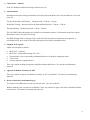
2 6. Action Items
Item Number: NB10–1201
NBIC Location: Part 1
Attachment Pages 2 – 15
Reformat NBIC Part 1 by expanding the general requirements section
General Description:
Subgroup:
Installation
Task Group:
M. Wadkinson (PM), B. Moore, S. Konopacki, E. Wiggins, D. Patten
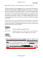
Meeting Action: The TG held a breakout session to discuss the comparison list of priority sections that
was provided by Brad Besserman to begin reviewing for common language that must reference the
General Section. M. Wadkinson later gave a progress report on the TG discussion to include that each
section has been assigned to a TG individual to research. Conference calls will take place resulting in
an expected proposal to be presented in the January 2016 meeting.
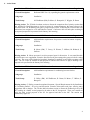
Item Number: NB12–0302
NBIC Location: Part 1
Attachment Pages 16 – 19
Add installation requirements for pressure vessels for human occupancy
General Description:
(PVHOs)
Subgroup:
Installation
Task Group:
B. Moore (PM), T. Creacy, K. Watson, T. Millette, M. Richards, G.
Scribner
Meeting Action: B. Moore presented a revision proposal open for discussion. It was stated that this
would become a new supplement. Extensive discussion took place amongst the group to include venting
concerns. The scope will be limited to hyperbaric chambers for medical use and single occupant at this
time. The TG is open to feedback on this proposal of which will be taken in to play in drafting a new
proposal to be presented in the January 2016 meeting.
Item Number: NB13–1101
NBIC Location: Part 1
Attachment Pages 20 – 21
Add installation requirements for condensing hot water boilers
General Description:
Subgroup:
Installation
Task Group:
G. Halley (PM), M. Wadkinson, D. Patten, B. Moore, T. Millete, P.
Bourgeois
Meeting Action: G. Halley presented an updated document, “Special Requirements for the Installation
of Condensing Boilers”, for review and discussion. Extensive discussions took place offering many
suggestions and or changes. The TG then held a breakout session to discuss the feedback given by the
SG, resulting in a further revised proposal to be taken to the SC for approval. There was a motion to
move the final revised proposal to the SC for approval and then to the MC. The motion was
unanimously approved.
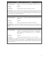
3 Item Number: NB14–0403
NBIC Location: Part 1
Attachment Page 22
Identify terms from Part 1 that need to be added to the index
General Description:
Subgroup:
Installation
Task Group:
B. Moore (PM), M. Richards, T. Creacy, K. Watson, M. Washington
Meeting Action: B. Moore presented a proposal to the SG for discussion and review. The SG is in
agreement of adding the items identified in the proposal to the index. This proposal will be put in a
format to be presented to the SC. Mr. Moore also found editorial errata’s of which he will be submitting
to the NB. Additionally, it was determined that a new action item will need to opened to address the
consistency of water gage glass and water glass.
Item Number: NB15–0104
NBIC Location: Part 1, 2.5.1.3
Attachment Pages 23 – 26
Edit or remove “Guide for Feedpump Differential” table because it gives
General Description:
inconsistent guidance
Subgroup:
Installation
Task Group:
E. Wiggins (PM), D. Patten, S. Konopacki, K. Watson
Meeting Action: A proposal was approved in the SC January 2015 meeting but did not pass in the MC.
The TG held a breakout session to discuss reworking the paragraph where the table is found. D. Patten
presented a revised proposal to the SG. There was a motion to move this revised proposal to the SC and
then to the MC for approval. The motion was unanimously approved.
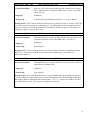
Item Number: NB15–0105
NBIC Location: Part 1
No Attachment
General Description: Research ASME B31.9 Building Piping code and assess its applicability to the
NBIC
Subgroup: Installation
Task Group: M. Wadkinson (PM), D. Patten, K. Watson, S. Konopacki, B. Moore, E. Wiggins
Meeting Action:
M. Wadkinson presented a progress report. Upon the completion of research on this item it was
determined that there is no applicability from B31.9 and therefore a motion was made to close this item
with no further action. The motion was unanimously approved with Mr. Washington not voting.
4 Item Number: NB15–0401
NBIC Location: Part 1, 2.5.1.3
Attachment Pages 27 – 30
Clarify boiler feedwater pump installation requirements for power
General Description:
boilers
Subgroup:
Installation
Task Group:
E. Wiggins (PM), D. Patten, S. Konopacki, K. Watson
Meeting Action: A proposal was approved in the January 2015 SC meeting but did not pass in the MC.
The TG held a break out session to discuss reworking this proposal. D. Patten presented a revised
proposal to the SG. There was a motion to move this revised proposal to the SC and then to the MC for
approval. The motion was unanimously approved.
Item Number: NB15–1001
NBIC Location: Part 1
No Attachment
Update “stamp” vs. “certification” language to maintain consistency with
General Description:
ASME code
Subgroup:
Installation
Task Group:
P. Bourgeois (PM), K. Watson, M. Richards, M. Wadkinson
Meeting Action: G. Scribner reported that B. Besserman continues to work on searching for and
highlighting language that needs to be changed, with a proposal forthcoming by the January 2016
meeting.
Item Number: NB15–1301
NBIC Location: Part 1, Section 2
Attachment Page 31
General Description:
Investigate overpressure protection requirement differences between Part
1 Section 2 – Power Boilers and Part 1 Section 3 – Heating Boilers,
specifically why aren’t the requirements of Part 1, 3.8.1.4 duplicated in
Part 1 Section 2?
Subgroup:
Installation
Task Group:
T. Millete (PM), M. Wadkinson, B. Moore, T. Creacy, K. Watson
Meeting Action: The TG held a breakout session to discuss wording in Section 2, Section 3, and CSD1, to work towards developing new text in Section 2. M. Wadkinson presented a proposal to the SG.
There was a motion to move the proposal to the SC and then to the MC for approval. The motion was
unanimously approved.
5 Item Number: NB15–1302
NBIC Location: Part 1, 2.8.1
Attachment Page 32
Why aren’t low water cutoffs required to have manual resets in Part 1,
General Description:
2.8.1? Manual resets are required in NBIC Part 1 Section 3 and CSD-1
Article CW-140
Subgroup:
Installation
Task Group:
T. Millete (PM), M. Wadkinson, B. Moore, T. Creacy, K. Watson
Meeting Action: The TG held a breakout session to discuss wording in Section 2, Section 3, and CSD1, to work towards developing new text in Section 2. M. Wadkinson presented a proposal to the SG.
There was a motion to move the proposal to the SC and then to the MC for approval. The motion was
unanimously approved with one not voting.
Item Number: NB15–2001
NBIC Location: Part 1, Section 2
No Attachment
General Description:
Add requirements for pressure operated controls for power boilers to be
consistent with CSD-1 CW-310 and NBIC Part 2, 2.2.10.6 l) 1)
Subgroup:
Installation
Task Group:
None assigned.
Meeting Action: Upon researching on this item it was determined this item was handled under item
NB15-1301. A motion was made to close this item with no further action. The motion was
unanimously approved.
Item Number: NB15–2101
NBIC Location: Part 1, 2.5.3.2
No Attachment
General Description:
Add requirements for a lockable disconnect for power boilers, similar to
requirements for heating boilers
Subgroup:
Installation
Task Group:
None assigned.
Meeting Action: Upon researching on this item it was determined that what is contained in Section 2
2.5.3 Power Boilers is contained in Section 3 Steam Heating Boilers, Hot-Water Heating Boilers, HotWater Supply Boilers, and Potable Water Heaters under 3.5.3.1 c) . A motion was made to close this
item with no further action. The motion was unanimously approved.
6 7. New Business New Interpretation (IN15–0501) (Attachment Pages 33 – 34)
TG assigned ‐ P. Bourgeois (PM), T. Creacy, B. Moore, K. Watson and D. Patten.
G. Scribner gave clarification to the SG. The assigned TG held a breakout session to discuss the proposal of an
answer. The proposed answer was presented to the SG. There was a motion to move the proposed answer to
the SC and then to the MC for approval. The motion was unanimously approved.
New Action Item (NB15–2303) (Attachment Pages 35 – 46)
A TG has been assigned ‐ M. Washington (PM), P. Bourgeios, T. Creacy, and K. Watson.
The TG held a breakout session to discuss and review whether the footnotes should be removed as a footnote or
is it Code language that could be incorporated in the body of the code, or is it a definition to be put in the
glossary.
New Action Item (NB15–0106) (Attachment Pages 47 – 51) To address Figure 3.7.5.1
A TG has been assigned ‐ B. Moore (PM), T. Creacy, and M. Washington
New Action Item (NB15– 0107) (Attachment Pages 52 – 55) To address 3.8.2.3 with BPV IV and CSD-1
A TG has been assigned ‐ M. Wadkinson (PM), B. Moore, S. Konopacki
8. Future Meetings
January 2016 – Corpus Christi, Texas
July 2016 – Columbus, Ohio
9. Adjournment
The meeting adjourned at 2.57 pm Respectfully Submitted, Jeanne Bock Secretary 7 Attachment Page 1
Attachment Page 1
Attachment Page 2
NB10-1201
Attachment Page 2
Attachment Page 3
NB10-1201
Attachment Page 3
Attachment Page 4
NB10-1201
Attachment Page 4
Attachment Page 5
NB10-1201
Attachment Page 5
Attachment Page 6
NB10-1201
Attachment Page 6
Attachment Page 7
NB10-1201
Attachment Page 7
Attachment Page 8
NB10-1201
Attachment Page 8
Attachment Page 9
NB10-1201
Attachment Page 9
Attachment Page 10
NB10-1201
Attachment Page 10
Attachment Page 11
NB10-1201
Attachment Page 11
Attachment Page 12
NB10-1201
Attachment Page 12
Attachment Page 13
NB10-1201
Attachment Page 13
Attachment Page 14
NB10-1201
Attachment Page 14
Attachment Page 15
NB10-1201
Attachment Page 15
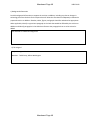
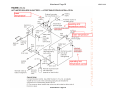
Attachment Page 16
NB12-0302
Proposed Supplement to Part 1, Section 6
Supplement 4
Installation of Pressure Vessels for Human Occupancy
(NOTES are reminders and placeholders for the Task Group.)
SUPPLEMENT Y
INSTALLATION OF PRESSURE VESSELS FOR HUMAN OCCUPANCY (PVHO) FOR
HYPERBARIC OXYGEN THERAPY
Y4.1 SCOPE
This Supplement provides general information to help owners, users, installers, and
jurisdictional authorities such as building officials understand these vessels and their unique
characteristics. The systems covered in this supplement include only medical systems for
Hyperbaric Oxygen Therapy (HBO). (NOTE: may need to add a definition to the
Glossary)
Y4.2 General
As medical devices, PVHOs are strictly regulated by federal, state, and local agencies. Such
agencies include medical licensing, Food and Drug Administration (NOTE: need to verify
and list others.)
a) Federal law restricts sales of these devices to sales by physicians or by order of a
physician.
b) Unique Characteristics
1) Fire hazard due to oxygen rich environment
2) Rapid decompression)
3) Pressure boundary valves
4) Purity of gases inside the vessel (NOTE: Not only is pure oxygen a potential fire
hazard, but a high concentration of gaseous hydrocarbons in the gas supply
can be as well.)
5) Exhaust and vent lines (NOTE: Some manufacturers prohibit manifolding in
their Installation Instructions to prevent possibly contaminate gases from
entering other vessels.)
6) Grounding the vessel (NOTE: Manufacturers have specific grounding
requirements unique to their vessels. This includes patient grounding with a
wrist strap.)
7) Life expectancy of acrylic vessel/windows (NOTE: This is dependent in part to the
manufacturers recommendations and PVHO-2)
Y4.3 RESPONSIBILITIES
Owners, user, and installers – (NOTE: due to the unique nature of these medical
devices, this section will explain that the owners, users, and installers have specific
responsibilities to follow the manufacturer’s installation instruction.)
Attachment
PagePage
1 of 4 16
Attachment Page 17
NB12-0302
Y4.4 CODES AND STANDARDS (NOTE: It will be vital to explain that these some of
the “possible” codes and standards, but following them is the explicit responsibility as
notes in the previous paragraph. In-service inspection responsibility will be explicitly
exempted. )
Depending the codes and standards adopted by the jurisdiction, the following are typically
used by manufacturers and installers.
a) Vessel Construction
1) ASME Section VIII Div 1 and Div 2
2) ASME PVHO-1
b) Piping
1) B31.1
2) B31.3
3) B31.9
c) Building – NFPA 99
Y4.5 INSTALLATION
The following aspects of installation shall be the responsibility of the owner/user/installer.
a) Construction of treatment room
b) Construction of the vessel
Hyperbaric chambers are manufactured in accordance with ASME Section VIII, Division 1
and the ASME PVHO-1 Safety Standard for Pressure Vessels for Human Occupancy.
They are designed to administer gases from pure O2 to air at pressures above
atmospheric
The basic components of the chamber are:
1) Acrylic windows
2) Quick opening access door(s)
3) Tie rods (for single occupancy chambers)
4) Seals
5) Door locking mechanism and safety interlock device(s)
6) Pressure control system
7) Ventilation control
8) Pressure relief device(s)
c) Operation
The manufacturer’s operating instructions shall be followed.
d) Pneumatic pressure control system
e) Communication system
f) Uses
The PVHO should be used for its intended purpose as prescribed by the manufacturer.
Attachment
PagePage
2 of 4 17
Attachment Page 18
NB12-0302
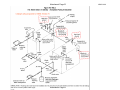
Y4.6 DESCRIPTION OF VESSEL
a) Overpressure Protection
1) Relief valve with open manual quick opening valve with frangible seal
2) Venting of relief valve (safe location outside the building)
3) No rupture disk PRDs
4) Exhaust
b) Controls (NOTE: This section will describe overall “typical” controls.)
c) Operation
The vessels should only be operated by qualified personnel under the direction of a fully
trained and authorized physician, and should only be used for the intended purpose.
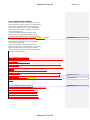
d) Unique Characteristics move to operation and safety
1) Fire hazard due to oxygen rich environment
2) Rapid decompression)
3) Pressure boundary valves
4) Purity of gases inside the vessel - Oxygen and medical breathing air supplied to the
vessel must be extremely clean (no more than 25 parts per million (ppm) of gaseous
hydrocarbons is allowed). A high concentration of gaseous hydrocarbons in the gas
supply is also a fire hazard.
5) Exhaust and vent lines should not be manifolded to prevent possibly contaminate
gases from entering other vessels.
6) Must be grounded according to manufacturer’s requirements. This includes patient
grounding with a wrist strap.
7) Just like scuba divers ascending from depth, patients must breath freely and not hold
their breath.
8) Life expectancy of acrylic vessel
e) Maintenance
1) Scratches in the acrylic windows
2) Door seals
(NOTE: Other ideas)
Permission to use some images from OEMs.
Process flow diagram
Installation, maintenance, and repair only by manufacturer trained technicians
Full-time attendant during patient therapy
Typical MAWP and relief valve setting/capacity
Max operating pressure
Emergency Vent Rate
Attachment
PagePage
3 of 4 18
Attachment Page 19
NB12-0302
References
A. Sechrist User’s Manual — Monoplace Hyperbaric Chamber Model 3300H/HR,
3600H/HR, and 4100H/HR Hyperbaric Chamber
B. Sechrist Installation Requirements and Technical Instruction Guide — Monoplace
Hyperbaric Chamber H-Series - Classic; H-Series with Gurney Storage and Low
Profile Gurney; and Models 3300H/HR, 3600H/HR and 4100H/HR
C. https://en.wikipedia.org/wiki/Hyperbaric_medicine
D. https://en.wikipedia.org/wiki/Undersea_and_Hyperbaric_Medical_Society
E. Undersea and Hyperbaric Medical Society https://www.uhms.org/
F. PVHO-1 and -2
G. NFPA 99
Attachment
PagePage
4 of 4 19
Attachment Page 20
NB13-1101
SUPPLEMENT 6
(Rev. July 14, 2015)
PART 1, SECTION 6
SPECIAL REQUIREMENTS FOR THE INSTALLATION OF CONDENSING BOILERS
S6.1
SCOPE
a) NBIC Part 1 Section 6 Supplement 6 provides requirements for various aspects of the installation
of Condensing Boilers which are unique from other products covered by this section.
b) This supplement is intended for the Owner/User/Installer only, and is based on Local, State or
National Building Codes requiring the installation of a Carbon Monoxide (CO) detector/alarm in
the boiler room.
S6.2
DETERMINATION OF ALLOWABLE OPERATING PARAMETERS
The allowable operating parameters of the combustion air intake and the exhaust gas venting shall be
in accordance with jurisdictional, environmental and manufacturers recommendations, as applicable.
S6.3
GENERAL REQUIREMENTS
Condensing boilers shall meet all the requirements of NBIC Part 1, Section 3 and this Supplement.
S6.4
FLUE GAS VENTING SYSTEM PIPING REQUIREMENTS
a) The vent piping shall be corrosion resistant and fabricated from either stainless alloy or plastic
material as defined by the boiler manufacturer and certified for the application.
b) The diameter of the vent piping shall be as defined by the boiler manufacturer and shall not be
reduced, except as allowed by the boiler manufacturer.
c) The “Total Equivalent Length” of the vent piping, and the pressure drop through the vent piping,
shall not exceed that stated in the Boiler Manufacturer’s Installation Manual. (Note Equivalent
Length includes the pressure loss effect of various pipe fittings, such as elbows, etc.) Horizontal
pipe runs shall slope toward the boiler and the condensate collection point.
d) The termination point of the vent piping shall be positioned such that there is no possibility of
vented flue gas being entrained in the combustion air intake, as defined by the manufacturer.
Additionally the vent termination shall be located above the highest known snowline for the
location involved, and be designed in such a manner, so as to prevent freezing.
Attachment Page 20
S6.5
SEALED COMBUSTION
SYSTEM
REQUIREMENTS
Attachment
Page
21
a) The location of the outside air intake, relative to the flue gas vent, shall be such that there shall be
no cross contamination with products of combustion or other airborne corrosive or hazardous
contaminants, as defined by the manufacturer. Additionally the location of the combustion air
intake shall be above the highest known snowline for the location involved.
b) The diameter, length and routing of the combustion air intake piping shall be such that the
pressure drop though the system, including any filters, shall not exceed the maximum pressure
drop stated by the boiler/burner manufacturer.
S6.6
CONDENSATE DRAIN SYSTEM REQUIREMENTS
The flue gas condensate from an individual boiler shall be collected at a single point, and the routing
of the drain piping shall include the following features:
1) A water trap, the height of which cannot be varied by field manipulation, and is in accordance
with boiler manufacturers requirements.
2) A visible means of ensuring that the condensate water trap contains the correct water level.
3) A discharge point away from occupied areas.
4) A method of controlling the pH of the condensate prior to its discharge into a sewer system, if
required by local building Codes.
Attachment Page 21
Attachment Page 22
NB14-0403
Item Number: NB14-0403 NBIC — Identify terms from Part 1 that need to be added to
the index.
Task Group: Brian Moore (PM), Mike Richards, Todd Creacy, Ken Watson, Milton
Washington
1.
Limit control appears 9 times, but is not indexed.
2.
Flue and flue gas – not indexed.
3.
Modular/modular boiler not indexed or defined in Glossary.
4.
"Scope" – not indexed; appears 27 times. Might be useful for someone looking for
the scope of a particular section.
5.
¶ 3.8.1.5 "water glass" is used 7 times and is not indexed. However, “Water-Gage
Glass” is indexed, but “gage glass” is not (used 27 times).
6.
"Settings" is only indexed 2 times but appears 14 times and "setting" as in "boiler
setting" is not indexed. It is, however, used in the context of “boiler setting” 4 times.
7.
PVHO is not indexed in Parts 1 or 2.
8.
CO2 and carbon dioxide (appears 12 times) are not indexed. CO2 does not appear
in a word search, but are used in Supplement 3.
9.
“shutoff” is not indexed. “Shutoff” is used 14 times and mostly followed by “valve”.
10. “de-rate” is not indexed. It is used 3 times.
11. “Installation report” is not indexed. It is used 21 times.
12. “Platform” is not indexed. It is used 20 times.
13. “Walkway is not indexed. It is used 16 times.
14. “Runway” is not indexed. It is used 21 times. It is, however, indexed with “Ladders
and Runways”.
Discovered during index review.
1. Errata or Typo - S3.1 "swimming pool PH control" Should be “pH”.
2.
Errata or Typo - "feed water" should be one word in the "Installation Report" in two
places.
Attachment Page 22
Attachment Page 23
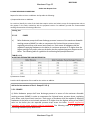
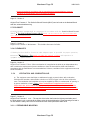
NB15‐0104 Action Item Request Form 8.3 CODE REVISIONS OR ADDITIONS Request for Code revisions or additions shall provide the following: a) Proposed Revisions or Additions For revisions, identify the rules of the Code that require revision and submit a copy of the appropriate rules as they appear in the Code, marked up with the proposed revision. For additions, provide the recommended wording referenced to the existing Code rules. Existing Text 2.5.1.3 PUMPS a) Boiler feedwater pumps shall have discharge pressure in excess of the maximum allowable working pressure (MAWP) in order to compensate for frictional losses, entrance losses, regulating valve losses, and normal static head, etc. Each source of feedwater shall be capable of supplying feedwater to the boiler at a minimum pressure of 3% higher than the highest setting of any safety valve on the boiler plus the expected pressure drop across the boiler. The following table is a guideline for estimating feed pump differential: TABLE 2.5.1.3
GUIDE FOR FEEDWATER PUMP DIFFERENTIAL
b) Statement of Need Provide a brief explanation of the need for the revision or addition. Add to the last sentence of Part 1. Pumps 2.5.1.3 a) 2.5.1.3 PUMPS a) Boiler feedwater pumps shall have discharge pressure in excess of the maximum allowable working pressure (MAWP) in order to compensate for frictional losses, entrance losses, regulating valve losses, and normal static head, etc. Each source of feedwater shall be capable of supplying feedwater to the boiler at a minimum pressure of 3% higher than the highest setting of any safety valve on the boiler plus the expected pressure drop across the boiler. Detailed engineering evaluation of the pump selection shall be performed. The following table is a guideline for estimating feedwater pump differential: Attachment Page 23
Attachment Page 24
NB15‐0104 c) Background Information Provide background information to support the revision or addition, including any data or changes in technology that form the basis for the request that will allow the Committee to adequately evaluate the proposed revision or addition. Sketches, tables, figures, and graphs should be submitted as appropriate. When applicable, identify any pertinent paragraph in the Code that would be affected by the revision or addition and identify paragraphs in the Code that reference the paragraphs that are to be revised or added. d) TG Assigned
Project Manager: Members: Don Patten Stan Konopacki and Ed Wiggins Attachment Page 24
Attachment Page 25
2.5
NB-23 2015
SOURCE REQUIREMENTS
SECTION 2
2.5.1FEEDWATER
"FOR COMMITTEE USE ONLY"
2.5.1.1VOLUME
The source of feedwater shall be capable of supplying a sufficient volume of water as determined by the boiler
manufacturer in order to prevent damage to the boiler when all the safety relief valves are discharging at full
capacity.
2.5.1.2CONNECTION
a) To prevent thermal shock, feedwater shall be introduced into a boiler in such a manner that the water
will not be discharged directly against surfaces exposed to high temperature gases or to direct radiation
from the flame.
b) For boiler operating pressures of 400 psig (2.8 MPa) or higher, the feedwater inlet through the drum
shall be fitted with shields, sleeves, or other suitable means to reduce the effects of temperature differentials in the shell or head.
c) Feedwater other than condensate return shall not be introduced through the blowoff.
d) Boilers having more than 500 sq. ft. (46.5 sq. m) of water heating surface shall have at least two means
of supplying feedwater. For boilers that are fired with solid fuel not in suspension, and boilers whose
setting or heat source can continue to supply sufficient heat to cause damage to the boiler if the feedwater supply is interrupted, one such means of supplying feedwater shall not be subject to the same
interruption as the first method. Boilers fired by gaseous, liquid, or solid fuel in suspension may be
equipped with a single means of supplying feedwater, provided means are furnished for the immediate
removal of heat input if the supply of feedwater is interrupted.
e) For boilers having a water heating surface of not more than 100 sq. ft. (9 sq. m), the feedwater piping
and connection to the boiler shall not be smaller than NPS 1/2 (DN 15). For boilers having a water heating surface more than 100 sq. ft. (9 sq. m), the feedwater piping and connection to the boiler shall not
be less than NPS 3/4 (DN 20).
f) Electric boiler feedwater connections shall not be smaller than NPS 1/2 (DN 15).
g) High-temperature water boilers shall be provided with means of adding water to the boiler or system
while under pressure.
2.5.1.3PUMPS
a) Boiler feedwater pumps shall have discharge pressure in excess of the maximum allowable working
pressure (MAWP) in order to compensate for frictional losses, entrance losses, regulating valve losses,
and normal static head, etc. Each source of feedwater shall be capable of supplying feedwater to the
boiler at a minimum pressure of 3% higher than the highest setting of any safety valve on the boiler plus
the expected pressure drop across the boiler. The following table is a guideline for estimating feedwater
pump differential:
Attachment Page 25
SECTION 2
(15)
9
2015 NATIONAL BOARD INSPECTION CODE
Attachment
Page 26
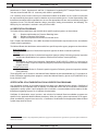
(15)
Boiler Pressure
Boiler Feedwater Pump Discharge Pressure
psig
(MPa)
psig
(MPa)
200
(1.38)
250
(1.72)
400
(2.76)
475
(3.28)
800
(5.52)
925
(6.38)
1,200
(8.27)
1,350
(9.31)
b) For forced-flow steam generators with no fixed steam or water line, each source of feedwater shall be
capable of supplying feedwater to the boiler at a minimum pressure equal to the expected maximum
sustained pressure at the boiler inlet corresponding to operation at maximum designed steaming capacity with maximum allowable pressure at the superheater outlet.
c) Control devices may be installed on feedwater piping to protect the pump against overpressure.
2.5.1.4VALVES
a) The feedwater piping shall be provided with a check valve and a stop valve. The stop valve shall be
located between the check valve and the boiler.
b) When two or more boilers are fed from a common source, there shall also be a globe or regulating
valve on the branch to each boiler located between the check valve and the feedwater source.
c) When the feedwater piping is divided into branch connections and all such connections are equipped
with stop and check valves, the stop and check valve in the common source may be omitted.
d) On single boiler-turbine unit installations, the boiler feedwater stop valve may be located upstream from
the boiler feedwater check valve.
e) If a boiler is equipped with duplicate feedwater supply arrangements, each such arrangement shall be
equipped as required by these rules.
f) A check valve shall not be a substitute for a stop valve.
g) A combination feedwater stop-and-check valve in which there is only one seat and disk and a valve
stem is provided to close the valve when the stem is screwed down shall be considered only as a stop
valve, a separate check valve shall be installed.
h) Whenever globe valves are used on feedwater piping, the inlet shall be under the disk of the valve.
i) Stop valves and check valves shall be placed on the inlet of economizers or feedwater-heating devices.
j) The recirculating return line for a high-temperature water boiler shall be provided with the stop valve, or
valves, required for the main discharge outlet on the boiler.
2.5.2FUEL
Fuel systems, whether firing coal, oil, gas, or other substance, shall be installed in accordance with jurisdictional and environmental requirements, manufacturer’s recommendations, and/or industry standards, as
applicable.
10
SECTION 2
Attachment Page 26
"FOR COMMITTEE USE ONLY"
SECTION 2
TABLE 2.5.1.3
GUIDE FOR FEEDWATER PUMP DIFFERENTIAL
Attachment Page 27
NB15-0401
Part 1, 2.5.1.3 – Remove “the expected pressure drop across the boiler” The second sentence in the paragraph 2.5.1.3 a) states that “Each source of feedwater shall be capable of supplying feedwater to the boiler at a minimum pressure of 3% higher than the highest setting of any safety valve on the boiler plus the expected pressure drop across the boiler.” For a natural circulation boiler there really isn’t any pressure drop across the boiler per se. Perhaps a more relevant factor is the pressure drop in the feedwater piping between the boiler feed pump and the boiler. However, the feedwater piping pressure drop is already addressed by the fact that the 3% over pressure is required to be supplied to the boiler. Section I PG‐61.1 has a similar requirement for the 3% overpressure, but without additional the words regarding pressure drop across the boiler. In order to be consistent with Section I, I am submitting the request for revision on the following page for consideration by the Committee. Response: PG‐61.1: Part 1, 2.5.1.3: Addresses feedwater supply at the boiler. Addresses pumps which include system losses beyond the boiler and feedwater supply throughout the entire system. Proposal: 2.5.1.3 PUMPS a) Boiler feedwater pumps shall have discharge pressure in excess of the maximum allowable working pressure (MAWP) highest set pressure relief valve in order to compensate for frictional losses, entrance losses, regulating valve losses, and normal static head, etc. Each source of feedwater shall be capable of supplying feedwater to the boiler at a minimum pressure of 3% higher than the highest setting of any safety pressure relief valve on the boiler proper plus the expected pressure drop across the boiler. Detailed engineering evaluation of the pump selection shall be performed. The following table is a guideline for estimating feedwater pump differential: Attachment Page 27
Attachment Page 28
NB15-0401
Rationale: Per email from Peter Molvie ‐ 1/28/15 Peter A. Molvie, P.E. Manager, Codes & Standards Cleaver‐Brooks Product Development 3232 W. Lancaster Ave. This fixes two problems. It corrects the inconsistency between the first sentence speaking in terms of pressure higher than MAWP and the second speaking of pressure in excess of the highest set safety valve. Secondly, it eliminates the counting of the piping pressure drop twice, making the words consistent with Section I. I have included the exact same words from Section I PG‐61.1 as highlighted below. Change wording to read: Boiler feedwater pumps shall have discharge pressure in excess of the
boiler rated pressure (MAWP) in order to compensate for frictional losses, entrance losses,
regulating valve losses, and normal static head, etc. Each source of feedwater shall be capable of
supplying feedwater to the boiler at a minimum pressure of 3% higher than the highest setting of
any safety valve on the boiler plus the expected pressure losses.drop across the boiler. The
following table is a guideline for estimating feed pump differential:
Attachment Page 28
Attachment Page 29
2.5
NB-23 2015
SOURCE REQUIREMENTS
SECTION 2
2.5.1FEEDWATER
"FOR COMMITTEE USE ONLY"
2.5.1.1VOLUME
The source of feedwater shall be capable of supplying a sufficient volume of water as determined by the boiler
manufacturer in order to prevent damage to the boiler when all the safety relief valves are discharging at full
capacity.
2.5.1.2CONNECTION
a) To prevent thermal shock, feedwater shall be introduced into a boiler in such a manner that the water
will not be discharged directly against surfaces exposed to high temperature gases or to direct radiation
from the flame.
b) For boiler operating pressures of 400 psig (2.8 MPa) or higher, the feedwater inlet through the drum
shall be fitted with shields, sleeves, or other suitable means to reduce the effects of temperature differentials in the shell or head.
c) Feedwater other than condensate return shall not be introduced through the blowoff.
d) Boilers having more than 500 sq. ft. (46.5 sq. m) of water heating surface shall have at least two means
of supplying feedwater. For boilers that are fired with solid fuel not in suspension, and boilers whose
setting or heat source can continue to supply sufficient heat to cause damage to the boiler if the feedwater supply is interrupted, one such means of supplying feedwater shall not be subject to the same
interruption as the first method. Boilers fired by gaseous, liquid, or solid fuel in suspension may be
equipped with a single means of supplying feedwater, provided means are furnished for the immediate
removal of heat input if the supply of feedwater is interrupted.
e) For boilers having a water heating surface of not more than 100 sq. ft. (9 sq. m), the feedwater piping
and connection to the boiler shall not be smaller than NPS 1/2 (DN 15). For boilers having a water heating surface more than 100 sq. ft. (9 sq. m), the feedwater piping and connection to the boiler shall not
be less than NPS 3/4 (DN 20).
f) Electric boiler feedwater connections shall not be smaller than NPS 1/2 (DN 15).
g) High-temperature water boilers shall be provided with means of adding water to the boiler or system
while under pressure.
2.5.1.3PUMPS
a) Boiler feedwater pumps shall have discharge pressure in excess of the maximum allowable working
pressure (MAWP) in order to compensate for frictional losses, entrance losses, regulating valve losses,
and normal static head, etc. Each source of feedwater shall be capable of supplying feedwater to the
boiler at a minimum pressure of 3% higher than the highest setting of any safety valve on the boiler plus
the expected pressure drop across the boiler. The following table is a guideline for estimating feedwater
pump differential:
Attachment Page 29
SECTION 2
(15)
9
2015 NATIONAL BOARD INSPECTION CODE
Attachment
Page 30
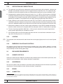
(15)
Boiler Pressure
Boiler Feedwater Pump Discharge Pressure
psig
(MPa)
psig
(MPa)
200
(1.38)
250
(1.72)
400
(2.76)
475
(3.28)
800
(5.52)
925
(6.38)
1,200
(8.27)
1,350
(9.31)
b) For forced-flow steam generators with no fixed steam or water line, each source of feedwater shall be
capable of supplying feedwater to the boiler at a minimum pressure equal to the expected maximum
sustained pressure at the boiler inlet corresponding to operation at maximum designed steaming capacity with maximum allowable pressure at the superheater outlet.
c) Control devices may be installed on feedwater piping to protect the pump against overpressure.
2.5.1.4VALVES
a) The feedwater piping shall be provided with a check valve and a stop valve. The stop valve shall be
located between the check valve and the boiler.
b) When two or more boilers are fed from a common source, there shall also be a globe or regulating
valve on the branch to each boiler located between the check valve and the feedwater source.
c) When the feedwater piping is divided into branch connections and all such connections are equipped
with stop and check valves, the stop and check valve in the common source may be omitted.
d) On single boiler-turbine unit installations, the boiler feedwater stop valve may be located upstream from
the boiler feedwater check valve.
e) If a boiler is equipped with duplicate feedwater supply arrangements, each such arrangement shall be
equipped as required by these rules.
f) A check valve shall not be a substitute for a stop valve.
g) A combination feedwater stop-and-check valve in which there is only one seat and disk and a valve
stem is provided to close the valve when the stem is screwed down shall be considered only as a stop
valve, a separate check valve shall be installed.
h) Whenever globe valves are used on feedwater piping, the inlet shall be under the disk of the valve.
i) Stop valves and check valves shall be placed on the inlet of economizers or feedwater-heating devices.
j) The recirculating return line for a high-temperature water boiler shall be provided with the stop valve, or
valves, required for the main discharge outlet on the boiler.
2.5.2FUEL
Fuel systems, whether firing coal, oil, gas, or other substance, shall be installed in accordance with jurisdictional and environmental requirements, manufacturer’s recommendations, and/or industry standards, as
applicable.
10
SECTION 2
Attachment Page 30
"FOR COMMITTEE USE ONLY"
SECTION 2
TABLE 2.5.1.3
GUIDE FOR FEEDWATER PUMP DIFFERENTIAL
Attachment Page 31
NB15‐1301 2.8.4 PRESSURE CONTROL Each automatically fired steam boiler shall be protected from overpressure by two pressure‐
operated controls. a) Each individual steam boiler or each system of commonly connected steam boilers shall have a control that will cut off the fuel supply when the steam pressure reaches an operating limit, which shall be less than the maximum allowable pressure. b) Each individual automatically fired steam boiler shall have a safety limit control, with a manual reset, that will cut off the fuel supply to prevent steam pressure from exceeding the maximum allowable working pressure of the boiler. Each control shall be constructed to prevent a pressure setting above the maximum allowable working pressure of the boiler. c) Shutoff valves of any type shall not be placed in the steam pressure connection between the boiler and the controls described in a) and b) above. These controls shall be protected with a siphon or equivalent means of maintaining a water seal that will prevent steam from entering the control. The connections to the boiler shall not be less than NPS 1/4 (DN 8), but where steel or wrought iron pipe or tubing is used, they shall not be less than NPS 1/2 (DN 15). The minimum size of an external siphon shall be NPS ¼ (DN 8) or 3/8 in. (10 mm) outside diameter nonferrous tubing. For manifold connections, the minimum size shall be as specified in the original code of construction. Attachment Page 31
Attachment Page 32
NB15-1302
2.8.5 AUTOMATIC LOW‐WATER FUEL CUTOFF AND/OR WATER FEEDING DEVICE a) Each automatically fired steam‐or vapor‐system boiler shall have an automatic low‐water fuel cutoff so located as to automatically cut off the fuel supply when the surface of the water falls to the lowest visible part of the water‐gage glass. If a water feeding device is installed, it shall be so constructed that the water inlet valve cannot feed water into the boiler through the float chamber and so located as to supply requisite feedwater. b) Such a fuel cutoff or water feeding device may be attached directly to a boiler. A fuel cutoff or water feeding device may also be installed in the tapped openings available for attaching a water glass directly to a boiler, provided the connections are made to the boiler with nonferrous tees or Y’s not less than NPS 1/2 (DN 15) between the boiler and water glass so that the water glass is attached directly and as close as possible to the boiler; the run of the tee or Y shall take the water glass fittings, and the side outlet or branch of the tee or Y shall take the fuel cutoff or water feeding device. The ends of all nipples shall be reamed to full‐size diameter. c) In addition to the requirements in a) and b) above, a secondary low‐water fuel cutoff with manual reset shall be provided on each automatically fired steam or vapor system boiler. d) Fuel cutoffs and water feeding devices embodying a separate chamber shall have a vertical drain pipe and a blowoff valve not less than NPS 3/4 (DN 20), located at the lowest point in the water equalizing pipe connections so that the chamber and the equalizing pipe can be flushed and the device tested. Attachment Page 32
Attachment Page 33
IN15-0501
PROPOSED INTERPRETATION
Inquiry No.
IN15-0501
Source
Michael Nelson – City of Albuquerque, Boiler Inspector
Subject
Edition
Part 1, 3.8.2.3
Question
Question 1: In the case of a hot‐water supply boiler and storage tank, is it
permissible to place the operating limit on the storage tank?
Reply
A1: Yes
Committee’s
Question
Committee’s
Reply
Rationale
Is it permissible to place the operating temperature control on a storage tank
located in a hot water supply system?
Yes
SC Vote
Unanimous
X
No. Affirmative
No. Negative
No. Abstain
No. Not Voting
NBIC Vote
Unanimous
No. Affirmative
No. Negative
No. Abstain
No. Not Voting
2013 Edition
Not prohibited by the NBIC. See Part 1 Section 3.8.2.3 a)
Negative Vote
Comments
Attachment Page 33
2015 NATIONAL BOARD INSPECTION CODE
Attachment
3.8.2.3
Page 34
TEMPERATURE CONTROL
a) Each individual hot-water heating or hot-water supply boiler or each system of commonly connected
boilers shall have a control that will cut off the fuel supply when the water temperature reaches an operating limit, which shall be less than the maximum allowable temperature.
SECTION 3
b) In addition to a) above, each individual automatically fired hot-water heating or hot-water supply boiler
shall have a safety limit control with manual reset that will cut off the fuel supply to prevent the water
temperature from exceeding the maximum allowable temperature at the boiler outlet.
3.8.2.4
LOW-WATER FUEL CUTOFF
a) Each automatically fired hot-water boiler shall have an automatic low-water fuel cutoff with manual
reset. The low-water fuel cutoff shall be designed for hot-water service, and it shall be so located as
to automatically cut off the fuel supply when the surface of the water falls to the level established in b)
below.
b) As there is no normal waterline to be maintained in a hot-water boiler, any location of the low-water fuel
cutoff above the lowest safe permissible water level established by the boiler manufacturer is satisfactory.
c) In lieu of the requirements for low-water fuel cutoffs in paragraph a), boilers requiring forced circulation
to prevent overheating of the tubes, coils, or vessel, shall have an accepted flow, and/or temperature-sensing device to prevent burner operation at a flow rate inadequate to protect the boiler unit
against overheating at all allowable firing rates. This safety control(s) shall shut down the burner and
prevent restarting until an adequate flow is restored and shall be independent of all other controls.
d) A means shall be provided for testing the operation of the external low-water fuel cutoff without resorting
to draining the entire system. Such means shall not render the device inoperable except as follows. If
the means temporarily isolates the device from the boiler during this testing, it shall automatically return
to its normal position. The connection may be so arranged that the device cannot be shut off from the
boiler except by a cock placed at the device and provided with a tee or lever-handle arranged to be
parallel to the pipe in which it is located when the cock is open.
3.8.2.5
MODULAR HOT-WATER HEATING BOILERS
a) Each module of a modular hot-water heating boiler shall be equipped with:
1) Pressure/altitude gage, see NBIC Part 1, 3.8.2.1;
2) Thermometer, see NBIC Part 1, 3.8.2.2; and
3) Temperature control, see NBIC Part 1, 3.8.2.3 a).
b) The assembled modular hot-water heating boiler shall be equipped with:
1) Temperature control, see NBIC Part 1, 3.8.2.3 b); and
2) Low-water fuel cutoff, see NBIC Part 1, 3.8.2.4.
46
SECTION 3
Attachment Page 34
"FOR COMMITTEE USE ONLY"
Each automatically fired hot-water heating or hot-water supply boiler shall be protected from over-temperature by two temperature-operated controls.
Attachment Page 35
NB15-2303
Action Item Request Form 8.3 CODE REVISIONS OR ADDITIONS Request for Code revisions or additions shall provide the following: a) Proposed Revisions or Additions For revisions, identify the rules of the Code that require revision and submit a copy of the appropriate rules as they appear in the Code, marked up with the proposed revision. For additions, provide the recommended wording referenced to the existing Code rules. Existing Text: There are 7 footnotes which occur throughout Part 1. 1 Caution, some Jurisdictions may independently administer a program of authorization for organizations to perform repairs and alterations within that Jurisdiction. 2 Fans – When combustion air is supplied to the boiler by an independent duct, with or without the employment of power ventilators or fans, the duct shall be sized and installed in accordance with the manufacturer’s recommendations. However, ventilation for the equipment room must still be considered. 3 (NB‐27) can be found on the National Board web‐site, www.nationalboard.org,. 4 Maintenance – This includes the removal of tubes. 5 Fans – When combustion air is supplied to the boiler by an independent duct, with or without the employment of power ventilators or fans, the duct shall be sized and installed in accordance with the manufacturer’s recommendations. However, ventilation for the equipment room must still be considered. 6 Side — The top side of the boiler shall mean the highest practicable part of the boiler proper but in no case shall the safety valves be located below the normal operating level and in no case shall the safety relief valve be located below the lowest permissible water level. 7 Pressure roll load, line load, and nip load are terms that are used interchangeably to refer to the interaction between the pressure roll(s) and the Yankee dryer. It is called “nip” load because the pressure roll is rubber‐covered and is pressed up against the Yankee with enough force to create a nip (or pinch) that forces the paper into line contact between the rolls and provides some mechanical dewatering. The paper then sticks onto the Yankee surface and follows the Yankee dryer for thermal dewatering by the steam‐heated Yankee surface. This “nip load” is called a “line load” because the units are load (force) per length of line contact. The units are pounds per linear inch (PLI) and kilonewtons per meter (kN/m). b) Statement of Need Provide a brief explanation of the need for the revision or addition. The desire is to avoid footnotes where possible in order to better manage changes and revisions within the context of the Part. It was determined that some footnotes could be easily placed within the paragraph and incorporated as part of the section. Where the footnotes can be blended back into the text, maintenance of the Part can be achieved in a more efficient manner. All but one of the footnotes were able to be merged into the paragraph. The one remaining footnote was better applied as a definition, therefore moved to this section. Attachment Page 35
Attachment Page 36
NB15-2303
c) Background Information Provide background information to support the revision or addition, including any data or changes in technology that form the basis for the request that will allow the Committee to adequately evaluate the proposed revision or addition. Sketches, tables, figures, and graphs should be submitted as appropriate. When applicable, identify any pertinent paragraph in the Code that would be affected by the revision or addition and identify paragraphs in the Code that reference the paragraphs that are to be revised or added. See the attached document. d) TG Assigned – SG Installation Project Manager: Milton Washington Members: Brian Moore, Paul Bourgeois, Ken Watson and Todd Creacy Attachment Page 36
Attachment Page 37
NB15-2303
Recommended Revisions for NB15-2303
Page X Introduction
Original Text, Footnote 1. Caution, some Jurisdictions may independently administer a program of
authorization for organizations to perform repairs and alterations within that Jurisdiction.
ACCREDITATION PROGRAMS
The National Board administers and accredits three specific repair programs1 as shown below:
“R”……….Repairs and Alterations to Pressure-Retaining Items
“VR”……..Repairs to Pressure Relief Valves
“NR”……..Repair and Replacement Activities for Nuclear Items
Part 3, Repairs and Alterations, of the NBIC describes the administrative requirements for the
accreditation of these repair organizations.
The National Board also administers and accredits four specific inspection agency programs as shown
below:
New Construction
Criteria for Acceptance of Authorized Inspection Agencies for New Construction (NB360) Inservice
Qualifications and Duties for Authorized Inspection Agencies (AIAs) Performing Inservice
Inspection
Activities and Qualifications for Inspectors of Boilers and Pressure Vessels (NB369)
Owner-User
Accreditation of Owner-User Inspection Organizations (OUIO) (NB-371) Owners or users may
be accredited for both a repair and inspection program provided the requirements for each
accreditation program are met.
Federal Government
Qualifications and Duties for Federal Inspection Agencies Performing Inservice Inspection
Activities (FIAs) (NB-390)
These programs can be viewed on the National Board Website at www.nationalboard.org. For questions
or further information regarding these programs contact the National Board by phone at (614) 888-8320
or by fax at (614) 847-1828
Caution, Note: Some Jurisdictions may independently administer and offer a program of authorization for
organizations who only wish to perform repairs and alterations within that Jurisdiction.
Page 12 – Section 2
Original Text, Footnote 2. Fans – When combustion air is supplied to the boiler by an independent duct,
with or without the employment of power ventilators or fans, the duct shall be sized and installed in
accordance with the manufacturer’s recommendations. However, ventilation for the equipment room must
still be considered.
2.5.4
VENTILATION AND COMBUSTION AIR
a) The equipment room shall have an adequate air supply to permit clean, safe combustion,
minimize soot formation, and maintain a minimum of 19.5% oxygen in the air of the boiler room.
The combustion and ventilation air should be supplied by either an unobstructed air opening or
by power ventilation or fans.2 Fans – When combustion air is supplied to the boiler by an
independent duct, with or without the employment of power ventilators or fans, the duct shall be
Attachment Page 37
Attachment Page 38
NB15-2303
sized and installed in accordance with the manufacturer’s recommendations. However,
ventilation for the equipment room must still be considered.
Page 15 – Section 2
Original Text, Footnote 3. The Guide for Blowoff Vessels (NB-27) can be found on the National Board
web-site, www.nationalboard.org
2.7.5 BLOWOFF
p) Boiler blowoff systems shall be constructed in accordance with the Guide for Blowoff Vessels
(NB-27) 3 The Guide for Blowoff Vessels (NB-27) which, can be found on the National Board website, www.nationalboard.org.
Page 27 – Section 3
Original Text, Footnote 4. Maintenance – This includes the removal of tubes.
3.3.4 CLEARANCES
c) Heating boilers shall be located so that adequate space is provided for proper operation,
maintenance4 Maintenance – This which, includes the removal of tubes and inspection of
equipment and appurtenances.
Page 30 – Section 3
Original Text, Footnote 5. Fans – When combustion air is supplied to the boiler by an independent duct,
with or without the employment of power ventilators or fans, the duct shall be sized and installed in
accordance with the manufacturer’s recommendations. However, ventilation for the equipment room must
still be considered.
3.5.4
VENTILATION AND COMBUSTION AIR
a) The equipment room shall ha)e an ade0uate air supply to permit clean, safe combustion,
minimize soot formation, and maintain a minimum of 19.5% oxygen in the air of the e0uipment
room. The combustion and ventilation air may be supplied by either an unobstructed air opening or
by power ventilation or fans.5 Fans – When combustion air is supplied to the boiler by an
independent duct, with or without the employment of power ventilators or fans, the duct shall be
sized and installed in accordance with the manufacturer’s recommendations. However, ventilation
for the equipment room must still be considered.
Page 47 – Section 3
Original Text, Footnote 6. Side — The top side of the boiler shall mean the highest practicable part of
the boiler proper but in no case shall the safety valves be located below the normal operating level and in
no case shall the safety relief valve be located below the lowest permissible water level.
3.9.1.1.1 PERMISSIBLE MOUNTING
Attachment Page 38
Attachment Page 39
NB15-2303
6
Safety valves and safety relief valves shall be located at the top side of the boiler. Side - The top side of
the boiler shall mean the highest practicable part of the boiler proper but in no case shall the safety valves
be located below the normal operating level and in no case shall the safety relief valve be located below
the lowest permissible water level. They shall be connected directly to a tapped or flanged opening in the
boiler, to a fitting connected to the boiler by a short nipple, to a Y-base, or to a valveless header
connecting steam or water outlets on the same boiler. Coil or header type boilers shall have the safety
valve or safety relief valve located on the steam or hot-water outlet end. Safety valves and safety relief
valves shall be installed with their spindles vertical. The opening or connection between the boiler and
any safety valve or safety relief valve shall have at least the area of the valve inlet.
Page 66 – Supplement 1
Original Text, Footnote 7. Pressure roll load, line load, and nip load are terms that are used
interchangeably to refer to the interaction between the pressure roll(s) and the Yankee dryer. It is called
“nip” load because the pressure roll is rubber-covered and is pressed up against the Yankee with enough
force to create a nip (or pinch) that forces the paper into line contact between the rolls and provides
some mechanical dewatering. The paper then sticks onto the Yankee surface and follows the Yankee
dryer for thermal dewatering by the steam-heated Yankee surface. This “nip load” is called a “line load”
because the units are load (force) per length of line contact. The units are pounds per linear inch (PLI)
and kilonewtons per meter (kN/m).
S1.2 ASSESSMENT OF INSTALLATION
4) Pressure roll load (line or nip load)7 due to pressing the wet web onto the dryer.
Overload protection is usually provided by a control valve that limits the pneumatic
or hydraulic forces on the roll loading arms such that the resultant nip load does not
exceed the allowable operating nip load.
Amend this footnote to Part 1, Section 9, Installation – Glossary of Terms
9.1 DEFINITIONS Pressure roll load – The terms line load, and nip load are terms that are used interchangeably to refer
to the interaction between the pressure roll(s) and the Yankee dryer. It is called “nip” load because the
pressure roll is rubber-covered and is pressed up against the Yankee with enough force to create a nip
(or pinch) that forces the paper into line contact between the rolls and provides some mechanical
dewatering. The paper then sticks onto the Yankee surface and follows the Yankee dryer for thermal
dewatering by the steam-heated Yankee surface. This “nip load” is called a “line load” because the units
are load (force) per length of line contact. The units are pounds per linear inch (PLI) and kilonewtons per
meter (kN/m). Attachment Page 39
2015 NATIONAL BOARD INSPECTION CODE
Attachment
Page 40
U.S. customary units or metric units may be used with this edition of the NBIC, but one system of units shall
be used consistently throughout a repair or alteration of pressure-retaining items. It is the responsibility of National Board accredited repair organizations to ensure the appropriate units are used consistently throughout
all phases of work. This includes materials, design, procedures, testing, documentation, and stamping. The
NBIC policy for metrication is outlined in each part of the NBIC.
ACCREDITATION PROGRAMS
1
R!!!"
#
$
%"
&
VR!!"
$
"
'()
NR!!"
"
#)
'
&
$*+"
#
+'
&/
)
0
'
of these repair organizations.
'
New Construction
Criteria for Acceptance of Authorized Inspection Agencies for New Construction (NB-360)
Inservice
89
'#:
&
#
;#&#<$
'&
)
&
#)
8'&
'
$
(
;%*=><
Owner-User
Accreditation of Owner-User Inspection Organizations (OUIO) (NB-371) Owners or users may be
'
)
0
'
program are met.
@
E)
89
'@
&
#
$
'&
)
&
#)
;@&#<;%*>F<
)
G
@0
further information regarding these programs contact the National Board by phone at (614) 888-8320 or by
fax at (614) 847-1828
CERTIFICATES OF AUTHORIZATION FOR ACCREDITATION PROGRAMS
#:
K
/
'
#:'
0
')
#
)
)
:L0
'
)+
'/
'#:
/
'#: + + ) ' G
0
0
'
)
+/
'#:
symbol stamp shall be issued.
1
Caution, some Jurisdictions may independently administer a program of authorization for organizations to perform repairs and alterations
within that Jurisdiction.
X
INTRODUCTION
Attachment Page 40
"FOR COMMITTEE USE ONLY"
parentheses. In Part 2, Supplement 6 and Part 3, Supplement 6 regarding DOT Transport Tanks, the metric
2015 NATIONAL BOARD INSPECTION CODE
Attachment
2.5.4
VENTILATION AND COMBUSTION AIR
a) The equipment room shall have an adequate air supply to permit clean, safe combustion, minimize soot
formation, and maintain a minimum of 19.5% oxygen in the air of the boiler room. The combustion and
ventilation air should be supplied by either an unobstructed air opening or by power ventilation or fans.2
b) Unobstructed air openings shall be sized on the basis of 1 sq. in. (650 sq. mm) free area per 2,000 Btu/
;WX=G<Y'
'
0
+
in the National Fire Protection Association (NFPA) standards for oil and gas burning installations for the
particular job conditions. The equipment room air supply openings shall be kept clear at all times.
c) Power ventilators or fans shall be sized on the basis of 0.2 cfm (0.0057 cu meters per minute) for each
1,000 Btu/hr (293 W) of maximum fuel input for the combined burners of all boilers located in the equipment room. Additional capacity may be required for any other fuel-burning equipment in the boiler room.
d) When power ventilators or fans are used to supply combustion air, they shall be installed with interlock
devices so that the burners will not operate without an adequate number of ventilators/fans in operation.
e) :
'
&/$\+]W^<
supply systems approved by the Jurisdiction are used.
f)
Care should be taken to ensure that steam and water lines are not routed across combustion air openings, where freezing may occur in cold climates.
2.5.5
(15)
LIGHTING
The equipment room should be well lit and it should have an emergency light source for use in case of power
failure.
2.5.6
EMERGENCY VALVES AND CONTROLS
#
%''))
'`+'+K+
Accessibility shall mean within a 6 ft. (1.8 m) elevation of the standing space and not more than 12 in. (305
mm) horizontally from the standing space edge.
2.6
DISCHARGE REQUIREMENTS
2.6.1
CHIMNEY OR STACK
Chimneys or stacks shall be installed in accordance with jurisdictional and environmental requirements, manufacturer’s recommendations, and/or industry standards, as applicable.
2.6.2
ASH REMOVAL
Ash removal systems shall be installed in accordance with jurisdictional and environmental requirements,
manufacturer’s recommendations, and/or industry standards, as applicable.
2.6.3
DRAINS
2.6.3.1
CONNECTION
2
Fans – When combustion air is supplied to the boiler by an independent duct, with or without the employment of power ventilators or
fans, the duct shall be sized and installed in accordance with the manufacturer’s recommendations. However, ventilation for the equipment
room must still be considered.
12
SECTION 2
Attachment Page 41
"FOR COMMITTEE USE ONLY"
SECTION 2
(15)
Page 41
Attachment Page 42
NB-23 2015
SECTION 2
S
d) Two independent slow-opening valves or a slow-opening valve and quick-opening valve may be
)
0)
'
%
valves or a slow-opening valve and a quick-opening valve, and the failure of one to operate cannot
affect the operation of the other.
f)
"FOR COMMITTEE USE ONLY"
Y
e) Straight-run globe valves or valves where dams or pockets can exist for the collection of sediment shall
not be used.
''))
))
'
:
:
'
$\;9]W<+
Y
\FF0';>*0
<
'
'
$*{^;9]F<
Y:
'
exceed NPS 2-1/2 (DN 65).
g) @
+
:
'''
$\;9]W<+
Y
'
boilers of 200 kW input or less. The minimum size should be NPS 3/4 (DN 20).
h) Fittings and valves shall comply with the appropriate national standard except that austenitic stainless
steel and malleable iron are not permitted.
i)
When the maximum allowable working pressure exceeds 100 psig (700 kPa), blowoff piping shall be at
XF
0
))
'
\]W
Ymum allowable working pressure of the boiler. When the maximum allowable working pressure exceeds
>FF;=]|$<+''
XF
0
))
shall be rated for at least the maximum allowable working pressure of the boiler plus 225 psi (1.6 MPa).
j)
#''+
Y
'
+
K
material so constructed that the piping may be readily inspected.
k) On a boiler having multiple blowoff pipes, a single master stop valve should be placed on the common
blowoff pipe from the boiler and one stop valve on each individual blowoff. Either the master valve or
the valves on the individual blowoff lines shall be of the slow-opening type.
l)
The discharge of blowoff pipes shall be located so as to prevent injury to personnel.
m) All waterwalls or water screens that do not drain back into the boiler and integral economizers forming
part of a boiler shall be equipped with blowoff piping and valves conforming to the requirements of this
paragraph.
n) Blowoff piping from a boiler should not discharge directly into a sewer. A blowoff tank, constructed to the
provisions of a code of construction acceptable to the Jurisdiction, shall be used where conditions do
not provide an adequate and safe open discharge.
o) Galvanized pipe shall not be used.
p) Boiler blowoff systems shall be constructed in accordance with the Guide for Blowoff Vessels (NB-27).3
q) Where necessary to install a blowoff tank underground, it shall be enclosed in a concrete or brick pit
with a removable cover so that inspection of the entire shell and heads of the tank can be made.
r)
Piping connections used primarily for continuous operation, such as deconcentrators on continuous
+
''
''))
0
0
'
pressure of any safety valve on the boiler drum and with the corresponding saturated-steam temperature. Further, such connections shall not exceed NPS 2-1/2 (DN 65).
3
ơ(NB-27) can be found on the National Board web-site, www.nationalboard.org,.
Attachment Page 42
SECTION 2
15
NB-23 2015
3.3.2
SECTION 3
d) Lugs or Hangers
+
+K
'
0
'
'
'
)
&/$\+@
**\\%
'
K
0
)
over the center of the welded contact surface. The bracket plates shall be spaced at least 2-1/2 in. (64
mm) apart, but this dimension shall be increased if necessary to permit access for the welding operation. The stresses computed by dividing the total load on each lug, hanger, or bracket, by the minimum
%
'
Y
]+XFF;\>|$<G
lugs, hangers, or brackets by welding, studs with not less than 10 threads/in. (approximately 4 threads/
cm) may be used. In computing the shearing stresses, the root area at the bottom of the thread shall
be used. The shearing and crushing stresses on studs shall not exceed that permitted by the code of
construction.
SETTINGS
Steam heating, hot-water heating, and hot-water supply boilers of wrought materials of the wet-bottom type
having an external width of over 36 in. (914 mm) shall be supported so as to have a minimum clearance of
\];*FW<
'
`'
G
*=
;>\^<
+
'
`
6 in. (150 mm), except when any part of the wet bottom is not farther from the outer edge than 12 in. (305
mm), this clearance shall be not less than 4 in. (100 mm). Boiler insulation, saddles, or other supports shall
be arranged so that inspection openings are readily accessible.
3.3.3
STRUCTURAL STEEL
a) If the boiler is supported by structural steel work, the steel supporting members shall be so located or
insulated that the heat from the furnace will not affect their strength.
b)
0
+'
L
mendations, and/or industry standards as appropriate.
3.3.4
CLEARANCES
a) Heating boilers shall have a minimum distance of at least 36 in. (914 mm) between the top of the
heating boiler and any overhead structure and at least 36 in. (914 mm) between all sides of the heating
+
+
0
)
)
at least 84 in. (2,135 mm) of clearance between the manhole opening and any wall, ceiling, piping, or
0
)
'
#
)
'
L
b) |
0
)
+'K+K
)
'
L
+
c)
0
)
'
+
+4
'
0
4
Maintenance – This includes the removal of tubes.
Attachment Page 43
SECTION 3
"FOR COMMITTEE USE ONLY"
ONLY
Attachment Page 43
27
2015 NATIONAL BOARD INSPECTION CODE
Attachment
Page 44
2) @
Y
+
'
needs be shut off.
CONTROLS AND HEAT GENERATING APPARATUS
a) %%
0
;`
'
<'
+'
+
0
:
SECTION 3
b) '
':)
0
)
:
'Y
0
)
that the unit was manufactured in accordance with that standard.
c) )
)
0
+'
L
+{+
3.5.4
VENTILATION AND COMBUSTION AIR
a) 0
)
0
+'
+:
'+'\>WY
'
0
and ventilation air may be supplied by either an unobstructed air opening or by power ventilation or
fans.5
b) :
'\0;=^W0<'
]+FFF{
;WX=G<Y'
'
0
+
@
$
#;@$#<''
0
K
c) $
)
'
:
'F]'3 (0.006 m3<'
\+FFF{;]>*G<
'Y'
'
'
{
0
#
0
'
'
0
0
room.
d) G
)
'
+
K
)
0
')
{'
e) G
+
'
)
'+
:
'
L
)
+)
'
0
f)
:
'
&/$\+*W^<
)
g) Care should be taken to ensure that steam and water lines are not routed across combustion air open+
'
:
3.5.5
LIGHTING
The boiler room should be well lit, and it should have an emergency light source for use in case of power
failure.
5
Fans – When combustion air is supplied to the boiler by an independent duct, with or without the employment of power ventilators or
fans, the duct shall be sized and installed in accordance with the manufacturer’s recommendations. However, ventilation for the equipmentroom must still be considered.
30
SECTION 3
Attachment Page 44
"FOR COMMITTEE USE ONLY"
3.5.3.3
Attachment Page 45
3.8.2.6
NB-23 2015
INSTRUMENTS, FITTINGS, AND CONTROLS MOUNTED INSIDE BOILER
JACKETS
POTABLE WATER HEATERS
3.8.3.1
TEMPERATURE CONTROLS
)
+
'
heater operation, shall have a separate high limit temperature actuated combustion control that will automatically cut off the fuel supply. The temperature range of the high limit temperature actuated control shall not
)
]\F@;>>/<
a) %
+
''
'
ply with a shutoff means other than the operating control valve. Separate valves may have a common
body.
b)
+
''
power to the operating controls.
c) %
+
''
`
to the burner mechanism.
d)
+
)
''
source of heat.
3.8.3.2
THERMOMETER
Each installed water heater shall have a thermometer so located and connected that it shall be easily readable. The thermometer shall be so located that it shall at all times indicate the temperature of the water in the
water heater at or near the outlet.
3.9
PRESSURE-RELIEVING VALVES
3.9.1
SAFETY VALVE REQUIREMENTS — GENERAL
'
0
++
'
))
3.9.1.1
MOUNTING SAFETY AND SAFETY RELIEF VALVES FOR STEAM HEATING,
HOT-WATER HEATING, AND HOT-WATER SUPPLY BOILERS
3.9.1.1.1
PERMISSIBLE MOUNTING
Safety valves and safety relief valves shall be located at the top side6 of the boiler. They shall be connected
`
+
+
%
+))
/
boilers shall have the safety valve or safety relief valve located on the steam or hot-water outlet end. Safety
6
Side — The top side of the boiler shall mean the highest practicable part of the boiler proper but in no case shall the safety valves be
located below the normal operating level and in no case shall the safety relief valve be located below the lowest permissible water level.
Attachment Page 45
SECTION 3
47
SECTION 3
3.8.3
"FOR COMMITTEE USE ONLY"
ONLY
#
++
0
'
K
provided the thermometer and pressure gage are visible through an opening or openings at all times.
2015 NATIONAL BOARD INSPECTION CODE
Attachment
The dryer is subjected to a variety of loads over its life. Some of the loads exist individually, while others
/
'
YK
0
mine the maximum allowable operating parameters. There are four loads that combine during normal
operation to create the maximum operating stresses, usually on the outside surface of the shell at the
axial center line. These loads and the associated protection devices provided to limit these loads are:
1) $
)
)
'
'
valve;
2) &
)
%
)
cates higher-than-allowable machine speed;
3) '
$
)
+
%''es the thermal load on the shell exterior from being cooled by the tissue sheet to being heated by
the hot air from the hood;
4) $
;
<7 due to pressing the wet web onto the dryer. Overload protection
is usually provided by a control valve that limits the pneumatic or hydraulic forces on the roll loading
arms such that the resultant nip load does not exceed the allowable operating nip load.
g) Steam pressure, inertial, and thermal gradient loads impose steady-state stresses. These stresses typically change when the dryer shell thickness (effective thickness for ribbed dryers) is reduced to restore
a paper-making surface, the grade of tissue is changed or speed of the dryer is changed.
SUPPL. 1
h) The pressure roll(s) load imposes an alternating stress on the shell face. The resulting maximum stress
is dependent on the magnitude of the alternating and steady-state stresses.
i)
(&&&+9)\+'
#|/
)
0
'
'
#
/
0
'
+
'
+
inertial, or pressure roll loads is provided. Hence, additional criteria must be applied by the manufacturer to account for all the steady-state and alternating stresses.
j)
0+
'
'
thickness reduction. Therefore, the manufacturer does not provide a single set of maximum allowable
operating parameters relating steam pressure, rotational speed, and pressure roll load for a single de
K
'
+
0
&
+
)
')
Y
'
K
K
9
%
/)
;
&/$\+
@
\\<
k) &
K
+
)
during shipment and installation into the paper machine. These nonstandard load events should be
recorded in an incident log. Examples of nonstandard load events include:
1) 9
)
K'
K
2) Scratches, gouges, dents in the Yankee dryer shell during packaging removal or installation into the
paper machine;
3) Y
)
'
K
'
&'
K
LY
7
Pressure roll load, line load, and nip load are terms that are used interchangeably to refer to the interaction between the pressure roll(s)
and the Yankee dryer. It is called “nip” load because the pressure roll is rubber-covered and is pressed up against the Yankee with enough force
to create a nip (or pinch) that forces the paper into line contact between the rolls and provides some mechanical dewatering. The paper then
sticks onto the Yankee surface and follows the Yankee dryer for thermal dewatering by the steam-heated Yankee surface. This “nip load” is
called a “line load” because the units are load (force) per length of line contact. The units are pounds per linear inch (PLI) and kilonewtons per
meter (kN/m).
66
SECTION 6
Attachment Page 46
"FOR COMMITTEE USE ONLY"
f)
Page 46
Attachment Page 47
NB15-0106
Action Item Request Form NB15‐0106 8.3 CODE REVISIONS OR ADDITIONS Request for Code revisions or additions shall provide the following: a) Proposed Revisions or Additions For revisions, identify the rules of the Code that require revision and submit a copy of the appropriate rules as they appear in the Code, marked up with the proposed revision. For additions, provide the recommended wording referenced to the existing Code rules. Existing Text: 3.8.2.3 TEMPERATURE CONTROL Each automatically fired hot‐water heating or hot‐water supply boiler shall be protected from over‐
temperature by two temperature‐operated controls. a)Each individual hot‐water heating or hot‐water supply boiler or each system of commonly connected boilers shall have a control that will cut off the fuel supply when the water temperature reaches an operating limit, which shall be less than the maximum allowable temperature. b) In addition to a) above, each individual automatically fired hot‐water heating or hot‐water supply boiler shall have a safety high temperature limit control with manual reset that will cut off the fuel supply to prevent the water temperature from exceeding the maximum allowable temperature at the boiler outlet. NOTE — Paragraph (a) above describes an operating control, while (b) describes a temperature limit control. See Figure 3.7.5.1‐c. b) Statement of Need Provide a brief explanation of the need for the revision or addition. Part 1 Section 3.8.2.3 text and Figure 3.7.5‐c callouts do not agree with each other and do not agree well with ASME Section IV HG‐613 or ASME CSD‐1 CW‐400 in the labeling of operating temperature controls and high limit temperature controls. The descriptive language among the NBIC, CSD‐1, and Section IV are similar but not identical. The Figures in the NBIC and Section IV are in harmony. The figures do not, however, match the text. A similar suggestion to correct the callouts has been made to Section IV. Attachment Page 47
Attachment Page 48
NB15-0106
c) Background Information Provide background information to support the revision or addition, including any data or changes in technology that form the basis for the request that will allow the Committee to adequately evaluate the proposed revision or addition. Sketches, tables, figures, and graphs should be submitted as appropriate. When applicable, identify any pertinent paragraph in the Code that would be affected by the revision or addition and identify paragraphs in the Code that reference the paragraphs that are to be revised or added. See attached for additional background. d) TG Assigned Project Manager: Brian Moore Members: Todd Creacy, Milton Washington Attachment Page 48
Attachment Page 49
ASME Section IV 2015 Edition
Action Item Request Form
NB15-0106 – additional background
NBIC 2015 – Part 2
CSD-1 2012
HG-613 TEMPERATURE CONTROL
Each automatically fired hot water
heating or hot water supply boiler shall
be protected from over‐temperature by
two temperature‐operated controls.
These temperature control devices shall
conform to UL 353, Standard for Limit
Controls, and shall be accepted by a
nationally recognized testing agency.
3.8.2.3 TEMPERATURE CONTROL
Each automatically fired hot-water
heating or hot-water supply boiler shall
be protected from over-temperature by
two temperature-operated controls.
(a) Each individual automatically fired
hot water heating or hot water supply
boiler shall have a high temperature
limit control that will cut off the fuel
supply to prevent water temperature
from exceeding its marked maximum
water temperature at the boiler outlet.
This control shall be constructed to
prevent a temperature setting above the
maximum.
a)Each individual hot-water heating or
hot-water supply boiler or each system
of commonly connected boilers shall
have a control that will cut off the fuel
supply when the water temperature
reaches an operating limit, which shall
be less than the maximum allowable
temperature.
(b) Each individual hot water heating or
hot water supply boiler shall have a
control that will cut off the fuel supply
when the system water temperature
reaches a preset operating
temperature, which shall be less than
the maximum water temperature.
NOTE — Paragraph(a) above
describes a temperature high limit
control, while (b) an operating
control. See Figure hg-703.2.
NB15-0106
b) In addition to a) above, each
individual automatically fired hot-water
heating or hot-water supply boiler shall
have a high temperature limit control
with manual reset that will cut off the fuel
supply to prevent the water temperature
from exceeding the maximum allowable
temperature at the boiler outlet.
NOTE — Paragraph (a) above
describes an operating control, while
(b) describes a temperature limit
control. See Figure 3.7.5.1-c.
Attachment Page 49
CW-400 TEMPERATURE CONTROLS
(b) Each automatically fired hot-water
boiler or each system of commonly
connected hot-water boilers shall have
at least one temperature-actuated
control to shut off the fuel supply when
the system water reaches a preset
operating temperature. This
requirement does not preclude the use
of additional operating control devices
where required.
(c) In addition to the temperature control
required in CW-410(b), each individual
automatically fired hot-water boiler unit
shall have a high temperature limit
control that will prevent the water
temperature from exceeding the
maximum allowable temperature. The
upper set point limit or the maximum
fixed stop limit of the selected control
shall not exceed the maximum allowable
temperature. Functioning of this control
shall cause safety shutdown and
lockout. The manual reset may be
incorporated in the temperature limit
control. Where a reset device is
separate from the temperature limit
control, a means shall be provided to
indicate actuation of the temperature
limit control.
EXCEPTION: Lockout is not required for
boiler units installed in residences, as
defined by the authority having
jurisdiction.
Attachment Page 50
Attachment Page 50
NB15-0106
Attachment Page 51
Attachment Page 51
NB15-0106
Attachment Page 52
NB15-0107
Action Item Request Form ITEM NB15‐0107 8.3 CODE REVISIONS OR ADDITIONS Request for Code revisions or additions shall provide the following: a) Proposed Revisions or Additions For revisions, identify the rules of the Code that require revision and submit a copy of the appropriate rules as they appear in the Code, marked up with the proposed revision. For additions, provide the recommended wording referenced to the existing Code rules. Existing Text: 3.8.2.3 TEMPERATURE CONTROL
Each automatically fired hot-water heating or hot-water supply boiler shall be protected from over-temperature
by two temperature-operated controls.
a) Each individual hot-water heating or hot-water supply boiler or each system of commonly connected
boilers shall have a control that will cut off the fuel supply when the water temperature reaches an operating
limit, which shall be less than the maximum allowable temperature.
b) In addition to a) above, each individual automatically fired hot-water heating or hot-water supply boiler
shall have a safety limit control with manual reset that will cut off the fuel supply to prevent the water
temperature from exceeding the maximum allowable temperature at the boiler outlet.
b) Statement of Need Provide a brief explanation of the need for the revision or addition. The text above conflicts with wording in Section IV and CSD-1. All 3 Codes need revision to harmonize
the language. An item exists in ASME in BPV IV and I am requesting an item in CSD-1.
Attachment Page 52
Attachment Page 53
NB15-0107
c) Background Information Provide background information to support the revision or addition, including any data or changes in technology that form the basis for the request that will allow the Committee to adequately evaluate the proposed revision or addition. Sketches, tables, figures, and graphs should be submitted as appropriate. When applicable, identify any pertinent paragraph in the Code that would be affected by the revision or addition and identify paragraphs in the Code that reference the paragraphs that are to be revised or added. d) TG Assigned
Project Manager: M. Wadkinson Members: B. Moore, S. Konopacki Attachment Page 53
Attachment Page 54
HG-613 TEMPERATURE CONTROL
Each automatically fired hot water heating or hot water
supply boiler shall be protected from over-temperature by
two temperature-operated controls. These temperature
control devices shall conform to UL 353, Standard for
Limit Controls, and shall be accepted by a nationally
recognized testing agency.
[a] Each individual automatically fired hot water
heating or hot water supply boiler shall have a high
temperature limit control that will cut off the fuel supply
to prevent water temperature from exceeding its at or below the marked
maximum water temperature at the boiler outlet. This
control shall be constructed to prevent a temperature
setting above the maximum.
[b] Each individual hot water heating or hot water
supply boiler shall have a control that will cut off the fuel
supply when the system water temperature reaches a
preset operating temperature, which shall be less than the
maximum water temperature.
NB15-0107
Formatted: Highlight
3.8.2.3 TEMPERATURE CONTROL
Each automatically fired hot-water heating or hot-water supply boiler shall be protected from
over-temperature
by two temperature-operated controls.
a) Each individual hot-water heating or hot-water supply boiler or each system of commonly
connected boilers
shall have a control that will cut off the fuel supply when the water temperature reaches an
operating
limit, which shall be less than the maximum allowable temperature.
b) In addition to a) above, each individual automatically fired hot-water heating or hotwater supply boiler
shall have a safety limit control with manual reset that will cut off the fuel supply to
prevent the water
temperature from exceeding the at or below the maximum allowable temperature at the boiler
outlet.
CW-400 TEMPERATURE CONTROLS
(12) CW-410 Requirements for Temperature Controls for
Hot-Water Heating and Supply Boilers
(a) Each temperature control device shall conform to
UL 353, Standard for Limit Controls, and shall be
accepted by a nationally recognized testing agency.
(b) Each automatically fired hot-water boiler or each
system of commonly connected hot-water boilers shall
Attachment Page 54
Formatted: Strikethrough
Formatted: Highlight
Formatted: Font: 12 pt
Attachment Page 55
have at least one temperature-actuated control to shut
off the fuel supply when the system water reaches a
preset operating temperature. This requirement does not
preclude the use of additional operating control devices
where required.
(c) In addition to the temperature control required in
CW-410(b), each individual automatically fired
hot-water boiler unit shall have a high temperature limit
control that will prevent the water temperature from
exceeding cut off the fuel supply at or below the maximum allowable temperature. The
upper set point limit or the maximum fixed stop limit
of the selected control shall not exceed the maximum
allowable temperature. Functioning of this control shall cause safety shutdown and lockout. The
manual reset
may be incorporated in the temperature limit control.
Where a reset device is separate from the temperature
limit control, a means shall be provided to indicate actuation
of the temperature limit control.
EXCEPTION: Lockout is not required for boiler units installed
in residences, as defined by the authority having jurisdiction.
(d) Each limit and operating control shall have its own
sensing element and operating switch, unless the boiler
temperature and limit control functions are performed
by a primary safety control system meeting all the
requirements of CW-210(a).
(e) A temperature limit control of the automatic or
manual reset type shall be electrically connected in
accordance with CE-110(i). Attachment Page 55
NB15-0107
Formatted: Font: 12 pt, Strikethrough
Formatted: Font: 12 pt
Formatted: Highlight
Formatted: Font: 12 pt