1
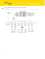
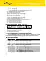
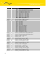
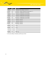
WWW.INFOPULSAS.LT [email protected] Expansion port USER´S GUIDE CNT CONTENTS Contents 1.SAFETY INSTRUCTIONS......................................................................................................4 2.CNT DESCRIPTION...............................................................................................................5 2.1. General description.............................................................................................................5 2.2. Examples of the expansion port usages.............................................................................5 2.3. Compatibility with Conel modems.......................................................................................5 2.4. Technical specifications......................................................................................................6 2.4.1 Analogy input.................................................................................................................6 2.4.2 Binary input....................................................................................................................6 2.4.3 Counter input.................................................................................................................6 2.4.4 Binary output..................................................................................................................7 2.5. Connector connection on the modem.................................................................................7 2.6. XC-CNT protocol.................................................................................................................9 2.7. Available communication protocols.....................................................................................9 2.8. Recommended settings for testing....................................................................................10 2.9. XC-CNT/RDS92 protocol description................................................................................10 2.10. XC-CNT/MODBUS RTU master protocol description.....................................................17 2.11. XC-CNT/MODBUS RTU slave protocol description........................................................19 2.12. XC-CNT MODBUS ASCII slave protocol description......................................................22 2.13. XC-CNT/IEC 60870-5-104 protocol description..............................................................26 2.14. XC-CNT/myIO protocol description.................................................................................28 2.15. XC-CNT/SMS protocol description..................................................................................29 2.16. Standard accessories......................................................................................................30 2.17. Product marking..............................................................................................................30 2.18. Production label...............................................................................................................30 3.LINKS TO RELATED PRODUCTS OF THE MANUFACTURER..........................................31 3.1 Products.............................................................................................................................31 4.COMPLAINTS PROCEDURE...............................................................................................32 5.WARRANTY..........................................................................................................................34 2 CONTENTS Symbols used Danger – important notice, which may have an influence on the user’s safety or the function of the device. Attention – notice on possible problems, which can arise in specific cases. Information, notice – information, which contains useful advices or interest notice. Conel limited., Sokolska 71, 562 04 Usti nad Orlici, Czech Republic Issue in CZ, 11/01/08 3 SAFETY INSTRUCTIONS 1. Safety instructions Please observe the following safety instructions: • The expansion port must be used in compliance with all applicable international and national laws and in compliance with any special restrictions regulating the utilization of the communication module in prescribed applications and environments. • Use only the original Conel company accessories. Thus you will prevent possible health risks and damage to the devices and ensure compliance with all relevant provisions. Unauthorised adjustments or use of unapproved accessories may result in damage to the expansion port and breach of applicable laws. Use of unapproved adjustments or accessories may lead to cancellation of guarantee, which has no effects on your legal rights. • Do not expose the expansion port to extreme conditions. Protect it from dust, moisture and heat. 4 CNT DESCRIPTION 2. CNT description 2.1. General description The expansion port CNT is created as independent signal counter which enables to use of the second hardware interface of Conel modems for next signal processing. This interface is physical connected on RJ45 connector on appropriate modem. The expansion port CNT is internal supplies from appropriate modem. The expansion port CNT is protected against inputs overload. At expansion port CNT including in modem it is possible use power supply management. At permanent idleness the expansion port CNT is switch to low power supply mode when demand current is very low (100 μA). Switch time to this status is program adjustable. The module wake up is possible by PORT2 status variation. The user interface CNT is for monitoring and processing of analogy and binary signals and to control (settings) of binary signal. To disposition are 2 counter and 2 binary inputs or 4 binary inputs, 2 analogy inputs a 1 binary output. The settings of binaries and counters inputs by the help of firmware in which it is defined the singles inputs and output. 2.2. Examples of the expansion port usages • • • modem (UR 5, ER 75i, CGU 04, CDL 400, CDL 800) expansion about next port next signal processing possibility easy expansion port exchange 2.3. Compatibility with Conel modems The expansion port CNT is possible use somewhere where it can extend modem about next port. Typically are it modems CGU 04, CGU 04i, UR 5, ER 75i, CDL 400 and CDL 800. 5 CNT DESCRIPTION 2.4. Technical specifications Name of product Power supply Supply power Environment Standards Inputs/outputs Expansion port CNT Voltage Sleep Operation Operating temperature Storage temperature Emission Immunity Safety Izolation 2x counter 2x analogy inputs Others 2.4.1 2x binary inputs 1x output (open collector) Voltage resistance Sleeping mode Internal 10 .. 30V 100 µA (counter is functional) 2 mA -20 .. +55 C -20 .. +85 C EN 55022/B ETS 300 342 EN 60950 EN 60747 Max. 100 Hz, ratio max. 1:10 0 .. 20 mA, Rin 100 Ohms reed contact 100 mA Permanent Controlled Analogy input On analogy input it detected current, converted to digital 10-bits value and modified by multiplicative and additive constant. Next the value is averaged on user settings and stored to PC memory. The basic range of input current is 0 – 20 mA at input resistance 100 Ω. Equal of value is: 12−bit. valueaddit.constant ∗multiplic. constant/1000 The sample period on analogy inputs is adjustable in range 0 ÷ 65535 seconds. At value 0 it is sampling once per second and measurement circuit is permanent switch on. At sampling it is possible to set time of measurement circuit switch from 16 ms to 375 ms. On the basis of signal change about bigger value then setting upper/lower limit is generated alarm. This alarm at defined settings of the GSM Datalogger DA4 generates message with values of the all active signals and send it to defined target. The alarm end is on the basis of bigger/lower signal change about set hysteresis than is upper/lower limit. 2.4.2 Binary input The binary input is potential-free contact which is 8 x per second sampling and sampling time is 1/64 seconds. For binary inputs is possible to set active level either log. 0 or log. 1. Choice active level can generate alarm. 2.4.3 Counter input The counter inputs are meters maximal to 100 Hz. The ratio impulses on input can be maximal 1:10, that means the impulse width mustn't be lower than 1/10 signal period. 6 CNT DESCRIPTION At lower width it isn't guaranteed the true evaluation of the metered signal. For metering of small frequencies (about mHz) it is important set the multiplicative constant which multiples metering frequency (flow) because of true evaluation. On the basis of signal change about bigger value then setting frequency upper limit is generated alarm. Alarm is possible send after time after which upper limit must be overrun. In case that it isn't any change on input, it is possible to define time after which the value on input will zeroes. 2.4.4 Binary output The binary output is realized by transistor with open collector. In inactive state (log 0) the transistor no transfer and is as switch off. In active state (log. 1) is transistor switch on and connect signal on ground (GND). Maximal switching current on output is 100 mA. Maximal voltage which can be on transistor collector is power supply voltage of the GSM Datalogger DA4. The impulse length is possible set in range 125 ÷ 8000 ms which is possible to send on output after impulses number setting (1 ÷ 65535) on input BIN1/CNT1. In sleep mode the all inputs and outputs values are metered and controlled. 2.5. Connector connection on the modem The connector is places on appropriate modem, the expansion port CNT is determine for signal processing. RJ45 panel socket Pin number Signal mark 7 Description Direction 1 BIN1/CNT1 Binary input/counter input Input 2 BIN2/CNT2 Binary input/counter input Input 3 BIN3 Binary input Input 4 BIN4 Binary input Input 5 GND Signal ground 6 OUT1 Binary output (open collector) Output 7 AN1 Analogy input Input 8 AN2 Analogy input Input CNT DESCRIPTION Typical connection of DA-4 measuring circuits for example: 8 CNT DESCRIPTION 2.6. XC-CNT protocol To enable datalogger functionality must be selected protocol XC-CNT on interface PORT 2. This protocol is used to read internat datalogger buffer of expander board XC-CNT. Data is archived to backuped modem RAM, sending by one of implemented protocols and control of main power supply in power management mode. 2.7. Available communication protocols Using XC-CNT protocol parameter „RF channel protocol“ can be choosed a number of communication protocols. List of protocols: RDS92 ● ● ● ● ● ● data sending by message code 0x30 remote XC-CNT configuration remote XC-CNT counters settings digital output remote control data logger reading, when power management is not active maximum message length 2048 B (1000 B for GPRS) MODBUS RTU master ● data sending by message code 0x10 (write registers) ● maximum message length 255 B MODBUS RTU slave ● data logger reading by message code 0x03 (read registers) ● maximum message length 255 B MODBUS ASCII slave ● possibility of port firmware configuration IEC 60870-5-104 ● data sending by telegrams type M_SP_TB_1, M_ME_TF_1 and M_IT_TB_1 ● telegrams processing type C_IC_NA_1 and C_CS_NA_1 ● outputs control by telegrams C_SC_NA_1 or C_SC_TA_1 ● data encapsuling into TCP or ARNEP MyIO data sending by HTTP protocol ● remote XC-CNT configuration ● digital output remote control ● SMS data sending by SMS ● maximum message length 160 characters ● 9 CNT DESCRIPTION 2.8. Recommended settings for testing Parameter Settings Sleep mode NO Samples period storing 1 min Wake-up period 0 min Period between communications 1 min ANx – sample period 0 sec 2.9. XC-CNT/RDS92 protocol description The DA4 automatically sends all logs to dispatching by message with 0x30 code after defined time (the DA4 logs request about storage). The dispatching confirms every logging by message with 0x31 code (answer on request about the DA4 logs storage) in which it can specify time, after which the DA4 will stay in receive yet. In case of need the dispatching have possibility to send message with 0x06 code (data request) or 0x08 code (data logging request) for snapping or the DA4 parameters set up. Request about the DA4 logs storage 10 1 1 2 1 1 1 Type Address Length Code PIN RecLen 2 4 2 2 2 2 ID Time Alarms DCVoltage BIN AN1 2 4 2 2 2 2 AN2 CNT1 CNT1FAct CNT1FAvg CNT1FMin CNT1FMax 4 2 2 2 2 2 CNT2 CNT2FAct CNT2FAvg CNT2FMin CNT2FMax ACVoltage 2 2 2 2 2 2 Temperature CIO1 CIO2 CIO3 CIO4 CIO5 8 to 54 8 to 54 ... 1 2. log 3. log ... Sum CNT DESCRIPTION Type – RDS92 message type (1 byte). 0x44 always. Address – station interface address (1 byte). Length – RDS92 message data part length (2 bytes, lower first). Code – request code about the DA4 logs storage (1 byte). 0x30 always. PIN – packet identification number (1 byte). RecLen – one log length (1 byte). 8 bytes – every log contents ID to Alarms array 16 bytes – every log contents ID to AN2 array 28 bytes – every log contents ID to CNT1FMax array 40 bytes – every log contents ID to CNT2FMax array 54 bytes – every log contents ID to CIO5 array ID – log number (2 bytes, higher first). Time – time stamp – seconds number from 1.1.1970 (4 bytes, higher first). Alarms – alarms actual state bits array (2 bytes, higher first). bit 0 – active level on input BIN1 bit 1 – active level on input BIN2 bit 2 – active level on input BIN3 bit 3 – active level on input BIN4 bit 4 – analogy input upper limit overrun AN1 bit 5 – analogy input lower limit overrun AN1 bit 6 – analogy input upper limit overrun AN2 bit 7 – analogy input lower limit overrun AN2 bit 8 – limit frequency overrun CNT1 bit 9 – limit frequency overrun CNT2 bit 10 – active level on input CIO1 bit 11 – active level on input CIO2 bit 12 – active level on input CIO3 bit 13 – active level on input CIO4 bit 14 – active level on input CIO5 bit 15 – power supply failure DCVoltage – power supply in tens mV (2 bytes, higher first). BIN – binary inputs states (2 bytes, higher first). bit 0 – level on input BIN1 bit 1 – level on input BIN2 bit 2 – level on input BIN3 bit 3 – level on input BIN4 bit 6 – level on output BOUT1 bit 10 – level on input CIO1 bit 11 – level on input CIO2 bit 12 – level on input CIO3 bit 13 – level on input CIO4 bit 14 – level on input CIO5 bit 15 – value validity CIO (DCVoltage, ACVoltage, Temperature and CIO1 to CIO5) AN1 – analogy input value AN1 (2 bytes, higher first, with marker). AN2 – analogy input value AN2 (2 bytes, higher first, with marker). CNT1 – counter status CNT1 (4 bytes, higher first). CNT1FAct – counter actual frequency CNT1 (2 bytes, higher first). CNT1FAvg – counter average frequency CNT1 (2 bytes, higher first). CNT1FMin – counter minimal frequency CNT1 (2 bytes, higher first). CNT1FMax – counter maximal frequency CNT1 (2 bytes, higher first). CNT2 – counter status CNT2 (4 bytes, higher first). CNT2FAct – counter actual frequency CNT2 (2 bytes, higher first). CNT2FAvg – counter average frequency CNT2 (2 bytes, higher first). CNT2FMin – counter minimal frequency CNT2 (2 bytes, higher first). CNT2FMax – counter maximal frequency CNT2 (2 bytes, higher first). ACVoltage – line voltage in tens mV (2 bytes, higher first). Temperature – station temperature in decimals ºC (2 bytes, higher first, with marker). CIO1 – analogy input value CIO1 (2 bytes, higher first). CIO2 – analogy input value CIO2 (2 bytes, higher first). CIO3 – analogy input value CIO3 (2 bytes, higher first). CIO4 – analogy input value CIO4 (2 bytes, higher first). CIO5 – analogy input value CIO5 (2 bytes, higher first). Sum – RDS92 message check sum (1 byte). 11 CNT DESCRIPTION Answer on request about the DA4 logs storage 1 1 2 1 1 1 Type Address Length Code PIN Time 1 Sum Type – RDS92 message type (1 byte). 0x44 always. Address – interface station address (1 byte). Length – RDS92 message data part length (2 bytes, lower first). 0x03 always. Code – confirmation code of the DA4 logs storage (1 byte). 0x31 always. PIN – confirmations packet identification number (1 byte). Time – seconds number after which the DA4 will stay in receive after confirmation receiving (1 byte). Sum – RDS92 message check sum (1 byte). Data request 1 1 2 1 2 2 Type Address Length Code 2 ... 2 2 ... 1 BlockLen1 ... BlockAdrX BlockLenX ... Sum 2 2 BlockCount BlockAdr1 Type – RDS92 message type (1 byte). 0x44 always. Address – interface station address (1 byte). Length – RDS92 message data part length (2 bytes, lower first). Code – data request code (1 byte). 0x06 always. BlockCount – block number (2 bytes, higher first). BlockAdr1 – first block start address (2 bytes, higher first). BlockLen1 – first block length (2 bytes, higher first). BlockAdrX – X-th block start address (2 bytes, higher first). BlockLenX – X-th block length (2 bytes, higher first). Sum – RDS92 message check sum (1 byte). Answer on data request 12 1 1 2 1 Type Address Length Code 2 N ... 2 2 N BlockLen1 Data1 ... BlockAdrX BlockLenX DataX ... 1 ... Sum BlockCount BlockAdr1 CNT DESCRIPTION Type – RDS92 message type (1 byte). 0x44 always. Address – interface station address (1 byte). Length – RDS92 message data part length (2 bytes, lower first). Code – Data request answer code (1 byte). 0x07 always. BlockCount – block number (2 bytes, higher first). BlockAdr1 – first block start address (2 bytes, higher first). BlockLen1 – first block length (2 bytes, higher first). Data1 – first block data (N bytes). BlockAdrX – X-th block start address (2 bytes, higher first). BlockLenX – X-th block length (2 bytes, higher first). DataX – X-th block length (N bytes). Sum – RDS92 message check sum (1 byte). Data loggin reguest 1 1 2 1 2 2 Type Address Length Code 2 N ... 2 2 N BlockLen1 Data1 ... BlockAdrX BlockLenX DataX ... 1 ... Sum 2 2 BlockCount BlockAdr1 Type – RDS92 message type (1 byte). 0x44 always. Address – interface station address (1 byte). Length – RDS92 message data part length (2 bytes, lower first). Code – request code about data loggin (1 byte). 0x08 always. BlockCount – block number (2 bytes, higher first). BlockAdr1 – first block start address (2 bytes, higher first). BlockLen1 – first block length (2 bytes, higher first). Data1 – first block data (N bytes). BlockAdrX – X-th block start address (2 bytes, higher first). BlockLenX – X-th block length (2 bytes, higher first). DataX – X-th block length (N bytes). Sum – RDS92 message check sum (1 byte). Answer on data loggin reguest 1 1 2 1 Type Address Length Code 2 N ... 2 2 N BlockLen1 Data1 ... BlockAdrX BlockLenX DataX ... 1 ... Sum Type – RDS92 message type (1 byte). 0x44 always. Address – interface station address (1 byte). Length – RDS92 message data part length (2 bytes, lower first). 13 BlockCount BlockAdr1 CNT DESCRIPTION Code – request code about data loggin (1 byte). 0x09 always. BlockCount – block number (2 bytes, higher first). BlockAdr1 – first block start address (2 bytes, higher first). BlockLen1 – first block length (2 bytes, higher first). Data1 – first block data (N bytes). BlockAdrX – X-th block start address (2 bytes, higher first). BlockLenX – X-th block length (2 bytes, higher first). DataX – X-th block length (N bytes). Sum – RDS92 message check sum (1 byte). The DA4 addresses space 14 Address Length Access Description 0x0200 1 -/W binary output control 0x0500 4 -/W counter status set up CNT1 0x0600 4 -/W counter status set up CNT2 0x1000 4 R/- actual log – ID 0x1004 4 R/- actual log – Time 0x1008 2 R/- actual log – Alarms 0x100A 2 R/- actual log – DCVoltage * 0x100C 2 R/- actual log – BIN * 0x100E 2 R/- actual log – AN1 0x1010 2 R/- actual log – AN2 0x1012 4 R/- actual log – CNT1 0x1016 2 R/- actual log – CNT1Freq 0x1018 2 R/- actual log – CNT1FreqAvg 0x101A 2 R/- actual log – CNT1FreqMin 0x101C 2 R/- actual log – CNT1FreqMax 0x101E 4 R/- actual log – CNT2 0x1022 2 R/- actual log – CNT2Freq 0x1024 2 R/- actual log – CNT2FreqAvg 0x1026 2 R/- actual log – CNT2FreqMin 0x1028 2 R/- actual log – CNT2FreqMax 0x102A 2 R/- actual log – ACVoltage * 0x102C 2 R/- actual log – Temperature * 0x102E 2 R/- actual log – CIO1 * 0x1030 2 R/- actual log – CIO2 * CNT DESCRIPTION 15 Address Length Access Description 0x1032 2 R/- actual log – CIO3 * 0x1034 2 R/- actual log – CIO4 * 0x1036 2 R/- actual log – CIO5 * 0x1038 8 R/- actual log – reservation 0x1040 64 R/- 2. log 0x1080 64 R/- 3. log ... ... ... ... 0xEFC0 64 R/- 896. log 0xF000 1 R/W sign bits array bit 0 – sleep mode bit 1 – send all values CIO bit 2 – send SMS behind communication failure bit 3 – send alarms status only bit 4 – send alarm end at once 0xF001 2 R/W sample storage period [min] 0xF003 2 R/W wake up period [min] 0xF005 2 R/W period between communications [min] 0xF007 2 R/W permit alarms • bit 0 – active level on input BIN1 • bit 1 – active level on input BIN2 • bit 2 – active level on input BIN3 • bit 3 – active level on input BIN4 • bit 4 – analogy input upper limit overrun AN1 • bit 5 – analogy input lower limit overrun AN1 • bit 6 – analogy input upper limit overrun AN2 • bit 7 – analogy input lower limit overrun AN2 • bit 8 – limit frequency overrun CNT1 • bit 9 – limit frequency overrun CNT2 • bit 10 – active level on input CIO1 • bit 11 – active level on input CIO2 • bit 12 – active level on input CIO3 • bit 13 – active level on input CIO4 • bit 14 – active level on input CIO5 • bit 15 – power supply failure 0xF009 1 R/W binary inputs negative logical • bit 0 – input BIN1 CNT DESCRIPTION Address Length Access Description • • • bit 1 – input BIN2 bit 2 – input BIN3 bit 3 – input BIN4 0xF00A 2 R/W AN1 - sampling period [sec] 0xF00C 2 R/W AN1 - multiplicative constant (with marker) 0xF00E 2 R/W AN1 - aditive constant (with marker) 0xF010 2 R/W AN1 - hysteresis value (with marker) 0xF012 2 R/W AN1 - lower limit (with marker) 0xF014 2 R/W AN1 - upper limit (with marker) 0xF016 2 R/W AN2 - sampling period [sec] 0xF018 2 R/W AN2 - multiplicative constant (with marker) 0xF01A 2 R/W AN2 - aditive constant (with marker) 0xF01C 2 R/W AN2 - hysteresis value (with marker) 0xF01E 2 R/W AN2 - lower limit (with marker) 0xF020 2 R/W AN2 - upper limit (with marker) 0xF022 2 R/W CNT1 - multiplicative constant 0xF024 2 R/W CNT1 - upper limit 0xF026 2 R/W CNT1 - limit overrun time [sec] 0xF028 1 R/W CNT1 - time for measuring reset [sec] 0xF029 2 R/W CNT2 - multiplicative constant 0xF02B 2 R/W CNT2 - upper limit 0xF02D 2 R/W CNT2 - limit overrun time [sec] 0xF02F 1 R/W CNT2 - time for measuring reset [sec] 0xF030 1 R/W bits 7-3: AN1 - measuring circuit switch time on • 0 → 1/64 sec • 1 → 2/64 sec • ... • 30 → 31/64 sec bits 2-0: AN1 - samples number for averaging • 0 → 1 sample • 1 → 2 samples • 2 → 4 samples 16 CNT DESCRIPTION Address Length Access Description • • 0xF031 1 R/W 4 → 8 samples 5 → 16 samples bits 7-3: AN2 - measuring circuit switch time on • 0 → 1/64 sec • 1 → 2/64 sec • ... • 30 → 31/64 sec bits 2-0: AN2 - samples number for averaging • 0 → 1 sample • 1 → 2 samples • 2 → 4 samples • 4 → 8 samples • 5 → 16 samples 0xF032 1 R/W communication repeat period [min] 0xF033 1 R/W data sending attempts number 0xF034 1 R/W active mode time [min] 0xF035 1 R/W quiescent level of binary outputs • bit 0 – output OUT1 0xF036 2 R/W dispenser – impulse number on input BIN1/CNT1 0xF038 1 R/W dispenser – impulse lenght on output OUT1 [1/8 sec] 0xFF00 2 -/W time on which the DA4 will stay on receiving yet * CIO value validity is indicates by BIN array 15th bit. 2.10. XC-CNT/MODBUS RTU master protocol description The DA4 automatically sends all logs to dispatching by message 0x10 code (entry values to more registers) after defined time and awaits appropriate confirmation from dispatching. DA4 logs storage request 17 1 1 2 2 1 2 Address FC RN RC BC RecLen CNT DESCRIPTION 2 4 2 2 2 2 ID Time Alarms DCVoltage BIN AN1 2 4 2 2 2 2 AN2 CNT1 CNT1FAct CNT1FAvg CNT1FMin CNT1FMax 4 2 2 2 2 2 CNT2 CNT2FAct CNT2FAvg CNT2FMin CNT2FMax ACVoltage 2 2 2 2 2 40 Temperature CIO1 CIO2 CIO3 CIO4 CIO5 2 CRC Address – dispatching address (1 byte) FC – function code (2 bytes, higher first). 0x10 always. RN – referential number (2 bytes, higher first). It specifies the data space start in which the data are written. Every master have dedicated space of the 256 registers where the first space register has number equal 256-multiple of the master address. RC – registers number (2 bytes, higher first). BC – bytes number (1 bytes). RecLen – log length (1 byte). 8 bytes – every log contents ID to Alarms array 16 bytes – every log contents ID to AN2 array 28 bytes – every log contents ID to CNT1FMax array 40 bytes – every log contents ID to CNT2FMax array 54 bytes – every log contents ID to CIO5 array ID – log number (2 bytes, higher first). Time – time stamp – seconds number from 1.1.1970 (4 bytes, higher first). Alarms – alarms actual state bits array (2 bytes, higher first). bit 0 – active level on input BIN1 bit 1 – active level on input BIN2 bit 2 – active level on input BIN3 bit 3 – active level on input BIN4 bit 4 – analogy input upper limit overrun AN1 bit 5 – analogy input lower limit overrun AN1 bit 6 – analogy input upper limit overrun AN2 bit 7 – analogy input lower limit overrun AN3 bit 8 – limit frequency overrun CNT1 bit 9 – limit frequency overrun CNT2 bit 10 – active level on input CIO1 bit 11 – active level on input CIO2 bit 12 – active level on input CIO3 bit 13 – active level on input CIO4 bit 14 – active level on input CIO5 bit 15 – power supply failure DCVoltage – power supply in tens mV (2 bytes, higher first). BIN – binary inputs states (2 bytes, higher first). bit 0 – level on input BIN1 bit 1 – level on input BIN2 bit 2 – level on input BIN3 bit 3 – level on input BIN4 bit 6 – level on output BOUT1 bit 10 – level on input CIO1 18 CNT DESCRIPTION bit 11 – level on input CIO2 bit 12 – level on input CIO3 bit 13 – level on input CIO4 bit 14 – level on input CIO5 bit 15 – value validity CIO (DCVoltage, ACVoltage, Temperature a CIO1 to CIO5) AN1 – analogy input value AN1 (2 bytes, higher first, with marker). AN2 – analogy input value AN2 (2 bytes, higher first, with marker). CNT1 – counter status CNT1 (4 bytes, higher first). CNT1FAct – counter actual frequency CNT1 (2 bytes, higher first). CNT1FAvg – counter average frequency CNT1 (2 bytes, higher first). CNT1FMin – counter minimal frequency CNT1 (2 bytes, higher first). CNT1FMax – counter maximal frequency CNT1 (2 bytes, higher first). CNT2 – counter status CNT2 (4 bytes, higher first). CNT2FAct – counter actual frequency CNT2 (2 bytes, higher first). CNT2FAvg – counter average frequency CNT2 (2 bytes, higher first). CNT2FMin – counter minimal frequency CNT2 (2 bytes, higher first). CNT2FMax – counter maximal frequency CNT2 (2 bytes, higher first). ACVoltage – line voltage in tens mV (2 bytes, higher first). Temperature – station temperature in decimals ºC (2 bytes, higher first, with marker). CIO1 – analogy input value CIO1 (2 bytes, higher first). CIO2 – analogy input value CIO2 (2 bytes, higher first). CIO3 – analogy input value CIO3 (2 bytes, higher first). CIO4 – analogy input value CIO4 (2 bytes, higher first). CIO5 – analogy input value CIO5 (2 bytes, higher first). CRC – 16-bit check sum of data packet (2 bytes). Answer on request about the DA4 logs storage 1 1 2 2 2 Address FC RN RC CRC Address – dispatching address (1 byte) FC – function code (2 bytes, higher first). 0X10 always. RN – referential number (2 bytes, higher first). RC – registers number (2 bytes, higher first). CRC – 16-bit check sum of data packet (2 bytes). 2.11. XC-CNT/MODBUS RTU slave protocol description The DA4 automatically stores the measuring data to its operation memory which the dispatching can reads by message with 0x03 code (reads of more registers values). The DA4 addresses space 19 Address Access Description 0x1000 R/- actual log – upper 16 bits of the log number 0x1001 R/- actual log – lower 16 bits of the log number 0x1002 R/- actual log – upper 16 bits of the time stamp 0x1003 R/- actual log – lower 16 bits of the time stamp 0x1004 R/- actual log – alarms status • bit 0 – active level on input BIN1 • bit 1 – active level on input BIN2 • bit 2 – active level on input BIN3 • bit 3 – active level on input BIN4 • bit 4 – analogy input upper limit overrun AN1 • bit 5 – analogy input lower limit overrun AN1 CNT DESCRIPTION Address Access Description • • • • • • • • • • 20 bit 6 – analogy input upper limit overrun AN2 bit 7 – analogy input lower limit overrun AN2 bit 8 – limit frequency overrun CNT1 bit 9 – limit frequency overrun CNT2 bit 10 – active level on input CIO1 bit 11 – active level on input CIO2 bit 12 – active level on input CIO3 bit 13 – active level on input CIO4 bit 14 – active level on input CIO5 bit 15 – power supply failure 0x1005 R/- actual log – power supply in tens mV * 0x1006 R/- actual log – binary inputs states • bit 0 – input BIN1 • bit 1 – input BIN2 • bit 2 – input BIN3 • bit 3 – input BIN4 • bit 6 – level on output BOUT1 • bit 10 – level on input CIO1 * • bit 11 – level on input CIO2 * • bit 12 – level on input CIO3 * • bit 13 – level on input CIO4 * • bit 14 – level on input CIO5 * • bit 15 – validity of CIO value 0x1007 R/- actual log – precalculate value AN1 (with marker) 0x1008 R/- actual log – precalculate value AN2 (with marker) 0x1009 R/- actual log – upper 16 bits CNT1 0x100A R/- actual log – lower 16 bits 0x100B R/- actual log – actual frequency CNT1 0x100C R/- actual log – average frequency CNT1 0x100D R/- actual log – minimal frequency CNT1 0x100E R/- actual log – maximal frequency CNT1 0x100F R/- actual log – upper 16 bits CNT2 0x1010 R/- actual log – lower 16 bits CNT2 0x1011 R/- actual log – actual frequency CNT2 0x1012 R/- actual log – average frequency CNT2 0x1013 R/- actual log – minimal frequency CNT2 0x1014 R/- actual log – maximal frequency CNT2 CNT DESCRIPTION Address Access Description 0x1015 R/- actual log – line voltage in tens mV * 0x1016 R/- actual log – station temperature in decimals ºC * 0x1017 R/- actual log – analogy input value CIO1 * 0x1018 R/- actual log – analogy input value CIO2 * 0x1019 R/- actual log – analogy input value CIO3 * 0x101A R/- actual log – analogy input value CIO4 * 0x101B R/- actual log – analogy input value CIO5 * 0x101C R/- actual log – reserve 0x101D R/- actual log – reserve 0x101E R/- actual log – reserve 0x101F R/- actual log – reserve 0x1020 R/- 2. log 0x1040 R/- 3. log ... ... ... 0xAFE0 R/- 1280. log * CIO value validity is indicates by BIN array 15th bit. 21 CNT DESCRIPTION 2.12. XC-CNT MODBUS ASCII slave protocol description The XC-CNT MODBUS ASCII slave protocol is communication protocol of firmware the expansion port CNT board. By the help of this protocol the station configures board software, reads her buffer, controls binary output and switch main station supply off. The expansion port CNT communicates by this protocol with bit rate 9600 bit/s (8N1). Address space Address 0x0000 0x0001 0x0002 0x0003 Access R/R/R/R/- 0x0004 0x0005 0x0006 0x0007 0x0008 0x0009 0x000A R/R/W R/W R/W R/W R/W R/- Description Firmware type Upper 16 bits of firmware version Lower 16 bits of firmware version Supports firmware characteristics • bit 0 – analogy input AN1 • bit 1 – analogy input AN2 • bit 2 – counter input CNT1 • bit 3 – counter input CNT2 • bit 4 – binary input BIN1 • bit 5 – binary input BIN2 • bit 6 – binary input BIN3 • bit 7 – binary input BIN4 • bit 8 – binary output OUT1 • bit 9 – automatic feeder control • bit 10 – fullduplex counter CNT1/CNT2 Maximal logs number in buffer Marker of log launching and alarms work Upper 16 bits of seconds number from 1.1.1970 Lower 16 bits of seconds number from 1.1.1970 Upper 16 bits of log actual number Lower 16 bits of log actual number Alarms actual status 0x0100 R/- Binary inputs status 0x0200 R/W Binary outputs status 0x0300 R/- Recalculate value of analogy input AN1 (with sign) 0x0400 R/- Recalculate value of analogy input AN2 (with sign) 0x0500 R/W Upper 16 bits of counter CNT1 value 22 CNT DESCRIPTION 0x0501 0x0502 0x0503 0x0504 0x0505 R/W R/R/R/R/- Lower 16 bits of counter CNT1 value Prompt frequency CNT1 Average frequency CNT1 Minimal frequency CNT1 Maximal frequency CNT1 0x0601 0x0601 0x0602 0x0603 0x0604 0x0605 R/W R/W R/R/R/R/- Upper 16 bits of counter CNT2 value Lower 16 bits of counter CNT2 value Prompt frequency CNT2 Average frequency CNT2 Minimal frequency CNT2 Maximal frequency CNT2 0x0F00 0x0F01 0x0F02 0x0F03 0x0F04 R/R/R/R/R/- 0x0F05 R/- 0x0F06 0x0F07 0x0F08 0x0F09 0x0F0A 0x0F0B 0x0F0C R/R/R/R/R/R/R/- 0x0000 always 0x0000 always Upper 16 bits of seconds number from 1.1.1970 Lower 16 bits of seconds number from 1.1.1970 Alarms status • bit 0 – active level on input BIN1 • bit 1 – active level on input BIN2 • bit 2 – active level on input BIN3 • bit 3 – active level on input BIN4 • bit 4 – analogy input lower limit overrun AN1 • bit 5 – analogy input upper limit overrun AN1 • bit 6 – analogy input lower limit overrun AN2 • bit 7 – analogy input upper limit overrun AN2 • bit 8 – limit frequency overrun CNT1 • bit 9 – limit frequency overrun CNT2 Binary inputs status • bit 0 – level on input BIN1 • bit 1 – level on input BIN2 • bit 2 – level on input BIN3 • bit 3 – level on input BIN4 • bit 6 – level on output BOUT1 Recalculate AN1 value (with sign) Recalculate AN2 value (with sign) Upper 16 bits CNT1 Lower 16 bits CNT1 Prompt frequency CNT1 Average frequency CNT1 Minimal frequency CNT1 23 CNT DESCRIPTION 0x0F0D 0x0F0E 0x0F0F 0x0F10 0x0F11 0x0F12 0x0F13 R/R/R/R/R/R/R/- Maximal frequency CNT1 Upper 16 bits of counter CNT2 value Lower 16 bits of counter CNT2 value Prompt frequency CNT2 Average frequency CNT2 Minimal frequency CNT2 Maximal frequency CNT2 0x1000 0x1001 0x1002 0x1003 0x1004 0x1005 0x1006 0x1007 0x1008 0x1009 0x100A 0x100B 0x100C 0x100D 0x100E 0x100F 0x1010 0x1011 0x1012 0x1013 R/R/R/R/R/R/R/R/R/R/R/R/R/R/R/R/R/R/R/R/- 1. log – upper 16 bits of log number 1. log – lower 16 bits of log number 1. log – upper 16 bits of time stamps 1. log – lower 16 bits of time stamps 1. log – alarms status 1. log – binary inputs status 1. log – recalculate value AN1 (with sign) 1. log – recalculate value AN2 (with sign) 1. log – upper 16 bits CNT1 1. log – lower 16 bits CNT1 1. log – prompt frequency CNT1 1. log – average frequency CNT1 1. log – minimal frequency CNT1 1. log – maximal frequency CNT1 1. log – upper 16 bits of counter CNT2 value 1. log – lower 16 bits of counter CNT2 value 1. log – prompt frequency CNT2 1. log – average frequency CNT2 1. log – minimal frequency CNT2 1. log – maximal frequency CNT2 0x1100 R/- 2. log 0x1200 R/- 3. log ... R/- ... 0xEF00 R/- 224. log 0xF000 -/W Samples stores period [min] 24 CNT DESCRIPTION 0xF001 -/W Allowed: • bit 0 – active level on input BIN1 • bit 1 – active level on input BIN2 • bit 2 – active level on input BIN3 • bit 3 – active level on input BIN4 • bit 4 – analogy input AN1 lower limit overrun • bit 5 – analogy input AN1 upper limit overrun • bit 6 – analogy input AN2 lower limit overrun • bit 7 – analogy input AN2 upper limit overrun • bit 8 – limit frequency CNT1 overrun • bit 9 – limit frequency CNT2 overrun 0xF100 -/W Binary inputs negative logical • bit 0 – input BIN1 • bit 1 – input BIN2 • bit 2 – input BIN3 • bit 3 – input BIN4 0xF200 -/W 0xF201 0xF202 -/W -/W Binary outputs normal level • bit 0 – output OUT1 Feeder – impulse number on input BIN1/CNT1 Feeder – impulse length on output OUT1 [1/8 sec] 0xF300 0xF301 0xF302 0xF303 0xF304 0xF305 0xF306 -/W -/W -/W -/W -/W -/W -/W 25 AN1 – samples period [sec] AN1 – multiplicative constant (with sign) AN1 – additive constant (with sign) AN1 – hysteresis value (with sign) AN1 – lower limit (with sign) AN1 – upper limit (with sign) bits 7-3: AN1 – metering circuit switch time • 0 → 1/64 sec • 1 → 2/64 sec • ... • 30 → 31/64 sec bits 2-0: AN1 – samples number for average • 0 → 1 sample • 1 → 2 samples • 2 → 4 samples • 4 → 8 samples • 5 → 16 samples CNT DESCRIPTION 0xF400 0xF401 0xF402 0xF403 0xF404 0xF405 0xF406 -/W -/W -/W -/W -/W -/W -/W AN2 – samples period [sec] AN2 – multiplicative constant (with sign) AN2 – additive constant (with sign) AN2 – hysteresis value (with sign) AN2 – lower limit (with sign) AN2 – upper limit (with sign) bits 7-3: AN2 – metering circuit switch time • 0 → 1/64 sec • 1 → 2/64 sec • ... • 30 → 31/64 sec bits 2-0: AN2 – samples number for average • 0 → 1 sample • 1 → 2 samples • 2 → 4 samples • 4 → 8 samples • 5 → 16 samples 0xF500 0xF501 0xF502 0xF503 -/W -/W -/W -/W CNT1 – multiplicative constant CNT1 – upper limit CNT1 – time of limit overrun [sec] CNT1 – time for metering reset [sec] 0xF600 0xF601 0xF602 0xF603 -/W -/W -/W -/W CNT2 – multiplicative constant CNT2 – upper limit CNT2 – time of limit overrun [sec] CNT2 – time for metering reset [sec] 0xFFFF -/W Switch main supply off on set time [min] 2.13. XC-CNT/IEC 60870-5-104 protocol description The DA4 automatically sends all logs to dispatching in M_SP_TB_1, M_ME_TF_1 and M_IT_TB_1 types telegrams after connection established. The DA4 can work up received commands C_IC_NA_1 (general inquiry), C_CS_NA_1 (time synchronization), C_SC_NA_1 (1-bit command without time) and C_SC_TA_1 (1-bit command with time). 26 CNT DESCRIPTION Data points 27 IOA Type Description 101 M_SP_TB_1 alarm – active level on input BIN1 102 M_SP_TB_1 alarm – active level on input BIN2 103 M_SP_TB_1 alarm – active level on input BIN3 104 M_SP_TB_1 alarm – active level on input BIN4 105 M_SP_TB_1 alarm – analogy input upper limit overrun AN1 106 M_SP_TB_1 alarm – analogy input lower limit overrun AN1 107 M_SP_TB_1 alarm – analogy input upper limit overrun AN2 108 M_SP_TB_1 alarm – analogy input lower limit overrun AN2 109 M_SP_TB_1 alarm – limit frequency overrun CNT1 110 M_SP_TB_1 alarm – limit frequency overrun CNT2 201 M_SP_TB_1 input level BIN1 202 M_SP_TB_1 input level BIN2 203 M_SP_TB_1 input level BIN3 204 M_SP_TB_1 input level BIN4 301 M_ME_TF_1 analogy input value AN1 302 M_ME_TF_1 analogy input value AN2 401 M_IT_TB_1 counter status CNT1 402 M_IT_TB_1 counter status CNT2 411 M_ME_TF_1 counter actual frequency CNT1 412 M_ME_TF_1 counter actual frequency CNT2 421 M_ME_TF_1 counter average frequency CNT1 422 M_ME_TF_1 counter average frequency CNT2 431 M_ME_TF_1 counter minimal frequency CNT1 432 M_ME_TF_1 counter minimal frequency CNT2 441 M_ME_TF_1 counter maximal frequency CNT1 442 M_ME_TF_1 counter maximal frequency CNT2 501 M_ME_TF_1 analogy input value CIO1 502 M_ME_TF_1 analogy input value CIO2 CNT DESCRIPTION IOA Type Description 503 M_ME_TF_1 analogy input value CIO3 504 M_ME_TF_1 analogy input value CIO4 505 M_ME_TF_1 analogy input value CIO5 601 M_ME_TF_1 power supply [V] 602 M_ME_TF_1 link voltage [V] 603 M_ME_TF_1 station temperature [ºC] Note.: The quantity of the send data points is depends on XC-CNT module firmware, alarms permit of the singles inputs and parameters “send alarms status only” and “send all values CIO”. Commands IOA Type Description 2201 C_SC_NA_1/ output control OUT1 C_SC_TA_1 2501 C_SC_NA_1/ output control CIO1 C_SC_TA_1 2502 C_SC_NA_1/ output control CIO2 C_SC_TA_1 2503 C_SC_NA_1/ output control CIO3 C_SC_TA_1 2504 C_SC_NA_1/ output control CIO4 C_SC_TA_1 2505 C_SC_NA_1/ output control CIO5 C_SC_TA_1 2.14. XC-CNT/myIO protocol description The XC-CNT MyIO protocol is communications protocol of the XC-CNT firmware for data transmition on web dispatching. By the help of this protocol the dispatching software configures the module software, read her buffer, controls binary output and switches off main station power supply. The XC-CNT MyIO protocol is client/server type. It behaves as client which it connects on dispatching server by the help of TCP connection in periodic time. As transport layer is used HTTP protocol. Dispatching server has the static IP address. The one communications relation has the following process: the client establish HTTP connection on server and by the help of method POST it send all its data. Server receive data 28 CNT DESCRIPTION and it send answer which it has up to 3 independent blocs: confirmation, output set up and configuration. The compulsory is only confirmation block, other blocks the server sends if it is need. In the end the client finish connection and it start count out time to next relation. 2.15. XC-CNT/SMS protocol description The DA4 automatically sends all logs in SMS messages on telephone number after defined time. Outgoing SMS format YYYY-MM-DD hh:mm:ss A=alarms V=voltage B1=bin B2=bin B3=bin B4=bin A1=analog A2=analog C1=count,freqact,freqavg,freqmin,freqmax C2=count,freq,freqavg,freqmin,freqmax YYYY – year (1900-2036). MM – month (01-12). DD – day (01-31). hh – hours (00-23). mm – minutes (00-59). ss – seconds (00-59). alarms – alarms status in hexadecimal format (0000-FFFF). bit 0 – active level on input BIN1 bit 1 – active level on input BIN2 bit 2 – active level on input BIN3 bit 3 – active level on input BIN4 bit 4 – analogy input upper limit overrun AN1 bit 5 – analogy input lower limit overrun AN1 bit 6 – analogy input upper limit overrun AN2 bit 7 – analogy input lower limit overrun AN2 bit 8 – limit frequency overrun CNT1 bit 9 – limit frequency overrun CNT2 bit 10 – active level on input CIO1 bit 11 – active level on input CIO2 bit 12 – active level on input CIO3 bit 13 – active level on input CIO4 bit 14 – active level on input CIO5 bit 15 – power supply failure voltage – power supply in volts (0.00-21.45). bin – binary input status (0-1). analog – precalculate analogy input value (-32768 – 32767). count – counter status (0-4294967295). freqact – actual frequency (0-65535). freqavg – average frequency (0-65535). freqmin – minimal frequency (0-65535). freqmax – maximal frequency (0-65535). Note.: The date, time, alarms status and power supply are sends in SMS always. Other values are sends only if given input is supports by XC - CNT module firmware. Example of the send SMS: 2006-01-16 09:15:40 A=0008 V=15.62 B1=1 B2=1 B3=0 A1=35 A2=3527 C1=12614,4,4,3,5 29 CNT DESCRIPTION Configuration ● GPRS connection establishing can disallow by entry empty APN. ● In case of the SMS illegility on some telephones, it is possibility switch the SMS format on 7-bit (only for firmware from 16.10.2007 and older) 2.16. Standard accessories 1. 2. 3. 4. Compliance certificate Complaint procedure Warranty User manual 2.17. Product marking Marking Supply Other Expansion port CNT Internal Inputs protection against overload, low power mode 2.18. Production label 30 LINKS 3. Links to related products of the manufacturer Related products and materials with a reference can be found on the manufacturer’s website – Conel company: www.conel.cz 3.1 Products CGU 04i – GPRS modem. UR 5 – UMTS router. ER 75i – EDGE router. CDL 800 – Radiomodem. CDL 400 – Radiomodem. 31 COMPLAINTS PROCEDURE 4. Complaints procedure Dear customer, The product you have purchased had passed manufacturer’s tests and its functions had been checked by our technician before sale. In case any defect shows up during the guarantee period that prevents normal use we ask you to follow the Complaints procedure when registering your claim. To make a possible complaint procedure easier please make sure when taking over the product your vendor has duly filled in all the relevant parts of the warranty, including date, seal and signature. This complaints procedure relates to the purchased products. This complaints procedure does not relate to the services provided. Guarantee period of the products Guarantee period of 24 months from the date of purchase is provided for the device, source, antenna, data cable and possible accessories. The date of purchase is at the same time date of takeover. Registering a claim It is necessary to register your claim at the vendor where the subject of the complaint has been purchased. The customer shall present duly filled warranty and the complete subject of the complaint. Subject of the complaint shall be presented in a condition adequate to that at the moment of purchase. Caution! The vendor is not responsible for keeping default settings or data saved in the subject of the complaint. The customer is obliged to clarify the defect or how it is displayed and what claim he intends to register. Processing the complaint The vendor shall provide a free remedy depending on particular conditions, or replace the subject of the complaint for a new product, or settle the matter in another manner in compliance with the Civil Code and the Act on consumer’s protection. As of the moment the claim is registered by the customer and the subject of the complaint is taken over by the vendor the guarantee period stops running. The guarantee period continues on the date of takeover of the repaired subject of the complaint or replaced faultless product by the customer, or should it not be taken over on the date the customer is obliged to take over the repaired or replaced product. In case the vendor replaces the subject of the complaint for a new product (including IMEI replacement) the original subject of the complaint becomes property of the vendor and the new product becomes property of the purchaser. Since takeover of the new product a new guarantee period starts. In the cases when the vendor settles the matter after agreement with the customer by replacement of the subject of the complaint for a faultless product the new guarantee expires. 1. After 12 months since the replaced product was taken over by the customer. 32 COMPLAINTS PROCEDURE 2. On the date when the original guarantee period (subject of the complaint) would have expired should it not have been replaced, whichever comes first. 3. The claim is deemed unsubstantiated when the defect is not found by the vendor processing the complaint or the defect is not covered by the guarantee under Article 3 of the procedure. 4. In case the claimed defect is not found and functionality is proven to the customer, the customer is obliged to pay demonstrable cost related to expert assessment of the claimed defect. 5. In case defect is found when processing the complaint that is not covered by the guarantee (extra-warranty repair), the vendor shall inform the customer and the customer shall inform the vendor whether he/she wishes to have the defect repaired for the price set. A protocol shall be made on exact conditions of the extra-warranty repair and signed by both the customer and the vendor. Should the customer not require remedy through an extra-warranty repair under the conditions, the device shall be returned to him/her after he/she pays the demonstrable cost of expert assessment. The guarantee does not cover defects incurred due to 1. Mechanical damage (fall and the like). 2. Use of inadequate, or not recommended sources and other accessories. 3. Connection of the product with non-standard accessories. 4. Installation or use of the product conflicting with the Manual or use for other purposes than usual for this type. 5. Improper manipulation, or an intervention of unauthorised person or other service than authorised by the manufacturer. 6. Effects of natural forces (flood, fire etc.) or other local phenomena (storm, overvoltage and the like). 7. Storage under unauthorised temperatures. 8. Operation in a chemically aggressive environment. Other conditions The fact that the subject of the complaint does not conform to parameters set for other similar product types shall not be considered a fault. To assess whether it is a case of covered fault the parameters stated in the technical documentation for the product are decisive. The guarantee expires in any case of changes to the subject of the complaint, or damaged or otherwise unreadable serial number. 33 WARRANTY 5. Warranty Device type Serial number Guarantee period (months) Vendor Date of purchase Seal of the vendor 34 WARRANTY 1 2 3 4 5 YES - NO YES - NO YES - NO YES - NO YES - NO Date of complaint registration Complaint protocol number Date of reception of the device in repair shop Date of finished repair Number of repair sheet Warranty repair New serial number of the device (IMEI) Notes Seal of the repair shop 35