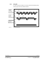
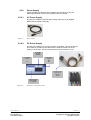
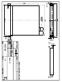
1
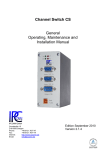
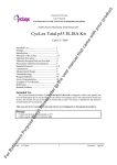
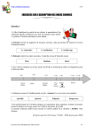
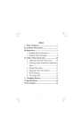
Industrial PC IPC191V2
General
Operating, Maintenance and
Installation Manual
Hardware Platform
Protocol Converter
Gundstraße 15
D-91056 Erlangen
Phone:
+49 9131 7677 47
Fax:
+49 9131 7677 78
Internet:
http://www.ipcomm.de
Email:
[email protected]
Edition November 2007
Version 1.0.2
Index
1
INTRODUCTION .............................................................................................................................. 1
2
HARDWARE DESCRIPTION .......................................................................................................... 2
2.1
GENERAL .................................................................................................................................... 2
2.2
HARDWARE COMPONENTS ........................................................................................................... 3
2.2.1
Mainboard .......................................................................................................................... 3
2.2.2
CPU-Module RS232 Interfaces ......................................................................................... 4
2.2.3
Hardlock Dongle ................................................................................................................ 5
2.2.4
8-Port RS232 Communication Board (RS232 Interfaces for remote communication) ...... 5
2.2.5
Ethernet Interfaces ............................................................................................................ 5
2.2.6
CompactFlash .................................................................................................................... 6
2.2.7
CMOS Lithium Battery ....................................................................................................... 6
2.2.8
CPU LED ........................................................................................................................... 7
2.2.9
Power Supply ..................................................................................................................... 8
3
INTERFACE CONFIGURATION ..................................................................................................... 9
3.1.1
3.1.2
3.1.3
3.1.4
3.1.5
Model A .............................................................................................................................. 9
Model C.............................................................................................................................. 9
Model B ............................................................................................................................ 10
Modell L ........................................................................................................................... 10
Modell D ........................................................................................................................... 10
4
TECHNICAL DATA........................................................................................................................ 11
5
APPENDIX ..................................................................................................................................... 12
5.1
IPC191 CAD DRAWING ............................................................................................................ 13
1
Introduction
All technical information, descriptions and illustrations contained in this Operating, Maintenance and
Installation Manual remain our property and shall not be used otherwise than for operating this
System, nor shall they be copied, reproduced or passed on to third parties or brought to their notice
without our prior written consent.
The information represented in this manual is in keeping with current standards and is subject to later
alterations.
This manual contains important instructions referring to safe installation, commissioning, operation
and maintenance.
Read this manual carefully before starting up the protocol converter and observe the instructions.
In order to comply with the guidelines for electro-magnetic compatibility in industrial PCs (or other
variants) only CE-certified components are used in compliance with project-specific requirements.
It is to be noted that the Protocol Converter (IPC191) has not been protected against lightning and the
operator should, if desired, take appropriate protective precautions.
All trademarks and brand names contained in this user manual are for identification purposes only and
can be owned by their respective holders.
Finally we want to draw your attention to the fact that any warranties with respect to delivered goods
will be invalid in the event that:
•
Operation, servicing and maintenance are not carried out accurately according to the
instructions, repairs are not carried out by our personnel or without our prior written consent.
•
Commissioning is not carried out by our personnel or we have not given our approval for the
commissioning or the commissioning is carried out by untrained personnel.
•
The unit is used inadequately, incorrectly, negligently or inappropriately or for a purpose other
than that originally intended.
•
The serial number is removed from the product.
For your protection, observe the following safety precautions when setting up your equipment:
•
Follow all cautions and instructions marked on the equipment.
•
Ensure that the voltage and frequency of your power source match the voltage and frequency
inscribed on the equipment's electrical rating label.
•
Never push objects of any kind through openings in the equipment. Dangerous voltages may
be present. Conductive foreign objects could produce a short circuit that could cause fire,
electric shock, or damage to your equipment.
Subject to alterations
IPCOMM GmbH
Gundstraße 15
D-91056 Erlangen
Version 1.0.2
-1-
IPC191 V2 Manual
Copyright © 2007 IPCOMM GmbH
All rights reserved
2
2.1
Hardware Description
General
As hardware platform for the protocol converter a 19” industrial PC is used.
This solution offers a high degree on flexibility, performance and reliability.
Mounting and intensive tests of the industrial PC are done in our company.
Before and after a 48 hour Burn-in Test each device must run through a
complete function test
All components are cooled passively. Only if critical system temperatures
have been reached two independent housing fans are switched on
automatically. Important for the selection of our components are particularly
items like quality, availability and a high durability.
The industrial PC consists of a 19“ chassis (1U) with an integrated Dual PCI
riser card for inserting the appropriate cards.
The mains power supply is 90 – 264 V AC, 127 – 373 V DC autorange,
optional 10 – 30 V DC power supply (other on request).
S/N, Model, Voltage
CompactFlash Card
Power
LED
DVD-RW Drive
Power
Button
CPU LED
Figure 1.
Subject to alterations
IPCOMM GmbH
Gundstraße 15
D-91056 Erlangen
COM 2
Port
Front view Industrial PC
Version 1.0.2
-2-
IPC191 V2 Manual
Copyright © 2007 IPCOMM GmbH
All rights reserved
On the figure 2 you can see the reverse side of our Industrial PC. The pin
assignments vary according to execution. Overview of the different models is
to be found under 3. Interface Configuration.
Main Power
Supply input
Monitor
LAN
LAN
PCI 2
Keyboard
PCI 1
e.g.: COM 4 – COM 11
COM 1
8 Port DB 9 Male connector
cable
(Optional: DB25 (Male, Female) )
Figure 2.
2.2
2.2.1
Overview Interfaces
Hardware Components
Mainboard
The Mini-ITX Mainboard is an ultra compact x86 dual LAN platform with all the
necessary interfaces. Its heart consists of a fanless highly efficient embedded
VIA Eden processor. The mainboard provides one DIMM slot for DDR
memory modules and supports up to 1GB system memory.
The following interfaces are provided by the CPU module:
•
•
•
•
•
•
2 x RS232 Interface (model-specific)
2 x RJ45 LAN Interface
Bi-directional Parallel Port
EIDE Interface
VGA Interface
Keyboard- / Mouse Port
Subject to alterations
IPCOMM GmbH
Gundstraße 15
D-91056 Erlangen
Version 1.0.2
-3-
IPC191 V2 Manual
Copyright © 2007 IPCOMM GmbH
All rights reserved
2.2.2
CPU-Module RS232 Interfaces
The installed mainboard provides 3 serial interfaces. However, depending on
the model these interfaces are completely or only partly available at the
chassis. COM 2 – COM 3 do not possess an RI signal.
The signal level of the serial interfaces can be changed between 5 and 12 V
by means of a jumper. COM3 interface is reserved for internal purpose and
can not be used.
This interface type is used for COM 1
SERIAL PORT
RS232 DTE
DB9 male connector
Pin
Direction
Description
1
INPUT
DCD Data Carrier Detect
2
INPUT
RXD Receive Data
3
OUTPUT
TXD Transmit Data
4
OUTPUT
DTR Data Terminal Ready
5
Figure 3.
GND Ground
6
INPUT
DSR Data Set Ready
7
OUTPUT
RTS Request To Send
8
INPUT
CTS Clear To Send
9
INPUT
RI
Ring Indicator
Pin Assignment of DB9 Interface (Computer) COM1
This interface type is used for COM 2 – COM 4
SERIAL PORT
RS232 DTE
DB9 male connector
Pin
Direction
Description
1
INPUT
DCD Data Carrier Detect
2
INPUT
RXD Receive Data
3
OUTPUT
TXD Transmit Data
4
OUTPUT
DTR Data Terminal Ready
5
GND Ground
6
INPUT
DSR Data Set Ready
7
OUTPUT
RTS Request To Send
8
INPUT
CTS Clear To Send
9
Figure 4.
Pin Assignment of DB9 Interface (Computer) COM2 – COM4
Subject to alterations
IPCOMM GmbH
Gundstraße 15
D-91056 Erlangen
Version 1.0.2
-4-
IPC191 V2 Manual
Copyright © 2007 IPCOMM GmbH
All rights reserved
2.2.3
Hardlock Dongle
The hardlock dongle is a hardware protection for the software. It must be
attached onto the parallel interface. Without hardlock dongle the software
does not boot!
Figure 5.
2.2.4
Hardlock Dongle
8-Port RS232 Communication Board (RS232 Interfaces for
remote communication)
Each IPC191 can be equipped with up to two serial interface cards.
SERIAL PORT
RS232 DTE
DB9 male connector
Pin
Direction
Description
1
INPUT
DCD Data Carrier Detect
2
INPUT
RXD Receive Data
3
OUTPUT
TXD Transmit Data
4
OUTPUT
DTR Data Terminal Ready
5
GND Ground
6
INPUT
DSR Data Set Ready
7
OUTPUT
RTS Request To Send
8
INPUT
CTS Clear To Send
9
Figure 6.
2.2.5
Pin Assignment of DB9 interface (Communication Board)
Ethernet Interfaces
The industrial PC features up to two Ethernet Interfaces generally. The
connection is set up via a 10/100 Mbps BaseT (RJ45) interface. Further
Interfaces with 10/100 Mbps or 10/100/1000 Mbps BaseT are possible on
request.
Subject to alterations
IPCOMM GmbH
Gundstraße 15
D-91056 Erlangen
Version 1.0.2
-5-
IPC191 V2 Manual
Copyright © 2007 IPCOMM GmbH
All rights reserved
2.2.6
CompactFlash
The CompactFlash card serves as a mass storage device, i.e. for storing the
operating system, the applications and configuration data. As a result the
disadvantages involved with the use of a rotating harddisk are avoided, thus
improving the reliability of the system substantially since a CompactFlash has
an MTBF of at least 4,000,000 hours.
The CompactFlash adapter is simply connected to the IDE bus of the CPU
module and treated just like a hard disk.
Push to take
CompactFlash
out
Figure 7.
CompactFlash Adapter
With the power supply switched off the CompactFlash card can simply be
taken out or inserted enabling a quick change to different hardware.
2.2.7
CMOS Lithium Battery
The onboard CMOS RAM stores system configuration data and has an
onboard battery power supply. The long-life Lithium battery has normally a
lifetime of at least 5 years.
If the CMOS battery is empty and the CMOS information has been deleted,
the CMOS-RAM is programmed by the BIOS with default settings.
The converter can be operated faultlessly even if the CMOS RAM is not
provided by the battery. After the battery has been changed only time and
date must be input.
For opening the case 3 screws on the top must be removed. The battery
holder is soldered in the Mainboard and well visible. Attention: Open-frame
power supplies are used. Because of this, the process should be carried out
only by experienced electronic engineers. The device must be completely
disconnected from any power supply. Before opening please push the power
button (without electricity supply) several times to eliminate residual voltages
of the power supply.
Battery replacement must be carried out by qualified specialists. CAUTION!
Incorrect replacement might cause the danger of explosion. Replace the
battery exclusively by the same type (3 V DC, CR2032). Used batteries are to
be disposed absolutely in accordance with the manufacturer's instructions.
Please pay attention to the correct polarity!
Subject to alterations
IPCOMM GmbH
Gundstraße 15
D-91056 Erlangen
Version 1.0.2
-6-
IPC191 V2 Manual
Copyright © 2007 IPCOMM GmbH
All rights reserved
2.2.8
CPU LED
The CPU LED shows the states of conversion software and operating system.
Following figure shows all possible indications:
Passive
Mode
(Standby)
0,5
ON
OFF
Active
Mode
0,5
5s
ON
OFF
Software has
stopped
ON
OFF
Figure 8.
CPU-LED indications
Subject to alterations
IPCOMM GmbH
Gundstraße 15
D-91056 Erlangen
Version 1.0.2
-7-
IPC191 V2 Manual
Copyright © 2007 IPCOMM GmbH
All rights reserved
2.2.9
Power Supply
Power supplies with different input voltages can be used in the IPC191.
Please pay attention to the correct polarity and input voltage.
2.2.9.1
AC Power Supply
By using AC voltages a specific power supply cable (Fig. 8) is supplied.
Please use this cable exclusively.
Figure 9.
Power Cable
2.2.9.2
DC Power Supply
By using DC voltages only a male connector is supplied. This connector has
to be used. By connecting the cable with the male connector the correct
polarity must be kept. The wire cross-section must be at least 1,5 mm².
Connection
for Earth
Potential
Power Supply
Input
Power Supply
Input
-
+
DC Power Cable
(Example, not
included in
delivery)
Label for correct
Power Voltage
(e. g. 24 V)
Figure 10.
DC Power Connection socket
Subject to alterations
IPCOMM GmbH
Gundstraße 15
D-91056 Erlangen
Version 1.0.2
-8-
IPC191 V2 Manual
Copyright © 2007 IPCOMM GmbH
All rights reserved
3
Interface Configuration
The following tables represent the configuration of the individual interfaces of
miscellaneous models. The setting is carried out either in the BIOS or via
jumpers on the appropriate card depending on the unit. The allocation
diagram of the link can be found in the documentation of the component.
3.1.1
Model A
Assembly
Device
I/O port
IRQ
Mainboard
ser1
3F8
4
ser2
ser3
en1
en2
2F8
3E8
PCI
PCI
3
5
PCI
PCI
Label
IOIOI (Chassis
rear)
IOIOI (Chassis
front)
CPU (Diagnose)
LAN1
LAN2
ser4
ser5
ser6
ser7
ser8
ser9
ser10
ser11
PCI
PCI
PCI
PCI
PCI
PCI
PCI
PCI
PCI
PCI
PCI
PCI
PCI
PCI
PCI
PCI
COM4
COM5
COM6
COM7
COM8
COM9
COM10
COM11
DB9ST
DB9ST
DB9ST
DB9ST
DB9ST
DB9ST
DB9ST
DB9ST
Assembly
Device
I/O port
IRQ
Connector
Mainboard
ser1
3F8
4
ser2
ser3
en1
en2
2F8
3E8
PCI
PCI
3
5
PCI
PCI
Label
IOIOI (Chassis
rear)
IOIOI (Chassis
front)
CPU (Diagnose)
LAN1
LAN2
DB9ST
NOT Connected
RJ45
RJ45
en3
PCI
PCI
LAN3
RJ45
ser4
ser5
ser6
ser7
ser8
ser9
ser10
ser11
PCI
PCI
PCI
PCI
PCI
PCI
PCI
PCI
PCI
PCI
PCI
PCI
PCI
PCI
PCI
PCI
COM4
COM5
COM6
COM7
COM8
COM9
COM10
COM11
DB9ST
DB9ST
DB9ST
DB9ST
DB9ST
DB9ST
DB9ST
DB9ST
UART 1
3.1.2
DB9ST
DB9ST
NOT Connected
RJ45
RJ45
Model C
Ethernet
10/100
BaseT
UART 1
Subject to alterations
IPCOMM GmbH
Gundstraße 15
D-91056 Erlangen
Connector
DB9ST
Version 1.0.2
-9-
IPC191 V2 Manual
Copyright © 2007 IPCOMM GmbH
All rights reserved
3.1.3
3.1.4
3.1.5
Model B
Assembly
Device
I/O port
IRQ
Mainboard
ser1
3F8
4
ser2
ser3
en1
en2
2F8
3E8
PCI
PCI
3
5
PCI
PCI
Label
IOIOI (Chassis
rear)
IOIOI (Chassis
front)
CPU (Diagnose)
LAN1
LAN2
UART 1
ser4
ser5
ser6
ser7
ser8
ser9
ser10
ser11
PCI
PCI
PCI
PCI
PCI
PCI
PCI
PCI
PCI
PCI
PCI
PCI
PCI
PCI
PCI
PCI
COM4
COM5
COM6
COM7
COM8
COM9
COM10
COM11
DB9ST
DB9ST
DB9ST
DB9ST
DB9ST
DB9ST
DB9ST
DB9ST
UART 2
ser12
ser13
ser14
ser15
ser16
ser17
ser18
ser19
PCI
PCI
PCI
PCI
PCI
PCI
PCI
PCI
PCI
PCI
PCI
PCI
PCI
PCI
PCI
PCI
COM4
COM5
COM6
COM7
COM8
COM9
COM10
COM11
DB9ST
DB9ST
DB9ST
DB9ST
DB9ST
DB9ST
DB9ST
DB9ST
Assembly
Device
I/O port
IRQ
Connector
Mainboard
ser1
3F8
4
ser2
ser3
en1
en2
2F8
3E8
PCI
PCI
3
5
PCI
PCI
Label
IOIOI (Chassis
rear)
IOIOI (Chassis
front)
CPU (Diagnose)
LAN1
LAN2
Assembly
Device
I/O port
IRQ
Mainboard
ser1
3F8
4
ser2
ser3
en1
en2
2F8
3E8
PCI
PCI
3
5
PCI
PCI
Label
IOIOI (Chassis
rear)
IOIOI (Chassis
front)
CPU (Diagnose)
LAN1
LAN2
ser4
PCI
PCI
COM4
DB9ST
DB9ST
NOT Connected
RJ45
RJ45
Model L
DB9ST
DB9ST
NOT Connected
RJ45
RJ45
Model D
USART 1
Subject to alterations
IPCOMM GmbH
Gundstraße 15
D-91056 Erlangen
Connector
Connector
DB9ST
DB9ST
NOT Connected
RJ45
RJ45
DB25ST
Version 1.0.2
- 10 -
IPC191 V2 Manual
Copyright © 2007 IPCOMM GmbH
All rights reserved
4
Chassis
Power Supply
Mainboard
Serial Cards
Mass Storage
Video
General
Operating
Environment
Technical Data
•
•
•
19“ rack mount chassis (1U)
Dual PCI riser card
Excellent air flow for maximum heat dissipation
•
•
•
•
Fanless
90 – 264 V AC, 127 – 373 V DC autorange, optional 24 V DC,
further voltages on request
Power consumption: max. 50 W (depending on the used type)
CE/TÜV certified
•
•
•
•
•
•
•
•
VIA Eden processor 600 MHz CPU
Max 1 GB DDR RAM
EIDE hard disk and flash disk drive interface
Digital I/O Interface
2 x high speed serial ports
Bi-directional parallel port
Real-time clock/calendar
2 x RJ45 10/100BaseT LAN interface onboard
•
•
•
•
Up to sixteen serial RS232 ports
DB9 male connectors, optional DB25 (Male, Female)
50 bps to 921.6Kbps transmission speed
16KV ESD Protection
•
•
•
•
•
•
•
Rugged CompactFlash, Industrial – Grade
Removable flash card
No Moving Parts
64 MB, max. 4 GB supported
Vibration: 15 G peak to peak max.
Shock: 1000 G max.
MTBF ≥ 4.000.000 hours
•
Standard VGA graphic adapter
•
•
•
•
All components are CE certified
Height: 1 U
Dimension (W x H x D): 19" x 1.75" x 15"
(482.6 mm x 44.45 mm x 381 mm)
Weight: 5,80 kg
•
•
•
Operating Temperature: 0° C to 45° C
Storage Temperature: 0° C to 60° C
Relative Humidity (non condensing): 5 % to 90 %
Assembled by IPCOMM GmbH/Germany
Subject to alterations
IPCOMM GmbH
Gundstraße 15
D-91056 Erlangen
Version 1.0.2
- 11 -
IPC191 V2 Manual
Copyright © 2007 IPCOMM GmbH
All rights reserved
5
Appendix
Subject to alterations
IPCOMM GmbH
Gundstraße 15
D-91056 Erlangen
Version 1.0.2
- 12 -
IPC191 V2 Manual
Copyright © 2007 IPCOMM GmbH
All rights reserved