1
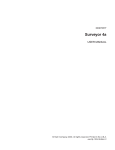
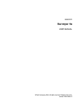
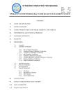
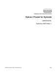
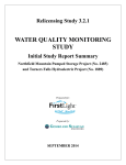
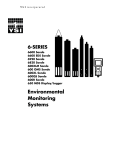
CHAPTER 8
CALIBRATING AND MAINTAINING
MULTIPROBE INSTRUMENTS
This chapter describes the calibration procedures for the most commonly used multiprobe
instruments. Since the TCEQ and the CRP planning agencies use Hydrolab and YSI
products, this section was written to address calibration and maintenance of those products.
If another multiprobe instrument (for example, Greenspan, In-Situ) is being used, refer to the
manufacturer’s instruction manual. Such other instruments must meet the post-calibration
error limits discussed in this chapter. The manufacturers’ manuals also detail other instrument
functions not described in this chapter, such as downloading data. For all instruments used,
manufacturers’ maintenance and calibration manuals must be kept for reference. All calibration
and maintenance activities must be recorded in a SWQM Multiprobe Calibration Logbook or
something similar (see Figures 8.3 and 8.4 for examples).
Calibrate parameters in the order given in this chapter and on the calibration log sheets—
specific conductance, pH, and DO (see Figures 8.3 and 8.4).
Calibration Logbooks for SWQM
Each instrument must have its own logbook to facilitate efficient review of calibration and
post-calibration results and maintenance procedures. The SWQM Program has developed
logbooks for use with Hydrolab and YSI instruments; they are available upon request from the
SWQM Program or the CRP. Both the Hydrolab and YSI calibration logbooks summarize the
calibration procedures and contain a number of individual calibration log sheets. See Figures 8.3
and 8.4 for YSI and Hydrolab calibration log sheets. The calibration log sheets are also available
on the Web (see Appendix A).
Keep full calibration logs on file for at least five years or as defined in a program or
project QAPP.
The following is basic information to be recorded in a log for each calibration.
# The date, time, and the initials of the person performing the calibration.
# The name and model number of the instrument being calibrated.
# The battery voltage.
# Initial instrument readings during immersion in the calibration standard before calibration
(temperature, value of standard, and initial reading).
# The calibrated to value obtained after adjusting the instrument to the calibration
standard value.
As needed, the following information is recorded for each instrument.
# Factory maintenance, including the date shipped for any repairs, the date returned from
repair, and a description of the repair work.
Calibration and Maintenance
8-1
10/2008
# In-house instrument maintenance, including the date and a description of any maintenance
activity (for example, battery replacement, probe cleaning, membrane replacement, stirrer
cleaning, reference-solution replacement).
Temperature-Controlled Environment
Take into consideration the environment in which the multiprobe instrument will be calibrated. It
is very important that the standards, buffers, rinse waters, and the instrument itself be acclimated
in a environment with stable temperature. Deionized (DI) water used for rinsing sensors should
be stored in a large container in the room normally used for calibration. The temperature of tap
water or DI water from a column used for rinsing is often very different from room temperature.
If the instrument, standards, buffers, and rinse water are transported to the field, and calibration or
a post-calibration check away from the laboratory becomes necessary, make sure the instruments
have acclimated to the same temperature. For example, place the solutions and instruments in a
motel room in the evening and calibrate in the morning.
Rinsing the Sensors
It is very important to rinse with DI water between the calibration of specific conductance
and pH.
■
Unscrew the cap and remove it from the calibration cup.
■
Fill the calibration cup about halfway with DI water.
■
Place the cap on the calibration cup.
■
Shake the sonde to rinse any contaminants that might interfere with calibration. Rinse with DI
water at least twice.
■
Repeat this procedure with the appropriate calibration standard. Rinse at least twice,
discarding the rinse each time. Fill the calibration cup with the standard and proceed with
calibration.
■
Warning: Do not allow the calibration cup to touch any of the sensors during this procedure.
Damage can occur if the cup makes hard contact with a sensor face.
Temperature-Sensor Check
Temperature is essential to the successful calibration of the other instrument parameters (DO,
pH, and specific conductance) so it is important to determine the continued accuracy of the
temperature probe. Multiprobe temperature sensors are typically very stable and accurate over a
long period of time. Temperature sensors are factory calibrated and cannot be adjusted by the
user. Calibration and maintenance (other than general cleaning) of the sensor are not required.
However, a check must be performed to ensure the proper calibration of other multiprobe water
quality sensors. Temperature data are used by every sensor in the sonde. A malfunctioning
temperature probe will cause calibration errors.
Check the temperature-sensor accuracy during routine instrument maintenance.
■
Using water acclimated to room temperature, put a laboratory thermistor or thermometer with
an accuracy of ±0.2EC and the instrument into the same water bath. This can be an ice chest
or a large bucket.
Calibration and Maintenance
8-2
10/2008
■
Allow the temperature to stabilize and record the reading from the multiprobe instrument and
the laboratory thermistor or thermometer in the calibration log. The difference between the
two temperatures must be within ±0.2°C.
■
If the temperature of the multiprobe is off by more than ±0.2°C, schedule the instrument for
recalibration by the manufacturer. If the temperature is off by ±0.5°C or more, data collected
between the accuracy checks may need to be flagged.
The laboratory thermistor or thermometer must be calibrated annually against a National Institute
of Standards and Technology (NIST) traceable thermometer. Some electronic thermistors can be
calibrated and are to be adjusted to the NIST value. Traditional thermometers cannot be changed;
check the NIST thermometer against the lab thermometer and determine a correction value. For
example, if the lab thermometer reads 23.1°C and the NIST thermometer reads 23.3°C, a
correction factor must be applied to the laboratory thermometer. Each time you take a reading,
add 0.2°C. Attach a correction-factor label to the thermometer. The calibration can be performed
for TCEQ personnel either during the annual audit or at the annual SWQM meeting. Other
monitoring organizations may choose an appropriate time for their annual calibration.
Calibration Standards and MultiprobeSensor Solutions
Store calibration standards and electrolyte solutions in a temperature-controlled environment.
Date containers upon receipt and again after opening them. Label any secondary containers with
their contents and expiration date. Commercially purchased calibration standards, which must be
NIST traceable, come with an expiration date. Do not use calibration standards for specific
conductance and pH beyond their expiration dates. However, expired calibration standards can be
used for rinsing probes during and after calibration. DO-electrolyte and pH reference solutions
have an indefinite shelf life.
Specific-Conductance Calibration Standards
Calibrate the conductivity system with a potassium chloride solution of known specific
conductance. Choose a standard solution with a specific conductance similar to, but higher than,
that of the water being sampled. For example, if the same instrument is used to sample water
bodies with specific-conductance values ranging from 250 to 800 µS/cm, calibrate with a
standard greater than 800 µS/cm, typically 1,500 µS/cm.
Calibrating Hydrolab Instruments
Specific Conductance
Series 3 (DataSonde 3, H20, Recorder, Reporter) and Quanta Sondes
Series 3 and Quanta Sondes require a one-point conductivity calibration (no zero needed).
■
Before calibration, rinse the sensors twice with DI water.
■
Use the rubber cap to cover the calibration cup and shake vigorously.
■
Rinse at least twice with the chosen standard solution and dispose of the solution.
■
Fill the calibration cup, covering the DO sensor, with the calibration standard and allow the
sensor to stabilize.
Calibration and Maintenance
8-3
10/2008
■
In Series 3 Sondes, check for air bubbles that may have become trapped in the conductivity
cell block. Remove bubbles if present.
■
Record the initial specific conductance value, value of standard, and temperature of the
calibration standard in the calibration log.
■
Using the four Function Keys under the LCD Screen, select Setup/Cal, Calibrate, and
then Sonde.
■
Use the arrow keys to scroll through the MiniSonde menu options.
■
Scroll to SpCond:µS/cm (or SpCond:mS/cm). Press Select.
■
Use the arrow keys to move the cursor left or right to enter the conductivity standard
concentration. Press Select to select the appropriate number. Enter the appropriate
concentration, and press Done.
■
The messages Calibration Successful, Press any key should appear. Select any function key
to remove the message.
■
Select Go Back and confirm the specific conductance reading from the display screen.
■
Record the value calibrated to in the calibration log.
Series 4, Series 4a, and Series 5 Sondes (DataSonde and MiniSonde)
Series 4, 4a, and 5 sondes require a two-point conductivity calibration.
■
Before calibration, rinse the sensors twice with DI water.
■
Replace the storage cup cap to cover the storage cup and shake vigorously.
■
Calibrate the zero point first by leaving the conductivity sensor in air.
■
Record the initial value, the value calibrated to, and the temperature in the calibration log.
■
Correct the initial specific-conductance value to zero and save the calibration.
■
Record the initial value and the value calibrated to (zero) in the calibration log, and the
temperature in the calibration log.
■
Calibrate the second point (“slope”) by rinsing at least twice with the chosen standard
solution.
■
Fill the storage cup with calibration standard, covering the DO sensor, and allow the sensor
to stabilize.
■
Record the initial specific-conductance value, the value of the standard, and the temperature
of the standard in the calibration log.
■
Correct the initial specific conductance value to match the standard value and save
the calibration.
■
Record the initial value, the value of the standard, the value calibrated to, and the temperature
in the calibration log.
pH Sensor
Calibrate the pH system with a buffer of pH 7.0, and either pH 4.0 for naturally acidic waters
or pH 10.0 for alkaline waters. The pH buffers contain high concentrations of phosphate.
Calibration and Maintenance
8-4
10/2008
During calibration, avoid leaving traces of buffer on equipment or at the workplace that could
contaminate water samples.
■
Before calibration, check the condition of the probes—ensure that they are intact and free
of surface films. If probes appear questionable, perform sensor maintenance according to
accepted procedures.
■
For Series 3 and Quanta Sondes, remove the storage cup from the sonde and replace with the
calibration cup. For Series 4, 4a, and 5 Sondes, remove the cap from the storage cup. Rinse
the sensors twice with DI water. Cover the cup and shake it.
■
Rinse at least twice with the pH 7 buffer solution.
■
Fill the cup, covering the DO sensor, with the pH 7 buffer solution and allow the sensor to
stabilize for two minutes.
■
Record the initial pH value and the temperature of the calibration standard in the
calibration log.
■
Using the temperature of the pH 7 buffer solution, determine the pH 7 calibration value.
See Table 8.3 for pH-calibration values corrected for temperature.
■
Record the calibration standard value in the calibration log.
■
Using the four function keys under the LCD Screen, select Setup/Cal, Calibrate, and
then Sonde.
■
Use the arrow keys to scroll through the MiniSonde menu options.
■
Scroll to pH. Press Select.
■
Use the arrow keys to move the cursor left or right to enter the pH standard concentration.
Press Select to choose the appropriate number, then press Done.
■
The messages Calibration Successful, Press any key should appear. Press any function key to
remove the message.
■
Record the value calibrated to in the calibration log.
■
Select Go Back and confirm the pH reading from the display screen.
■
Repeat this procedure with either pH 4 or pH 10 buffer solution. Choose a pH buffer that best
represents the pH of the environment to be monitored.
Dissolved-Oxygen Sensor
DO concentrations in water are measured using either a polarographic electrode or
optical sensors.
DO-sensor calibration requires a current uncorrected reading for barometric pressure (BP).
See below, “Barometric Pressure.”
Clark Polarographic DO Cell
Precalibration
Clean the sonde and the stirrer using running water to remove debris. Check the condition of the
DO membrane—ensure it is intact and free of wrinkles, bubbles, and surface films. Inspect the
appearance of the DO sensor and the electrolyte. Note any discoloration. If probes appear
Calibration and Maintenance
8-5
10/2008
questionable, perform sensor maintenance according to accepted procedures. Confirm that the
circulator or stirrer is operational.
Calibration
■
Remove the DO sensor guard if present. Invert the sonde (point its sensors upward) with the
calibration cup in place.
■
Carefully blot the DO membrane dry using a Kimwipe or a soft towel. Be careful not to apply
pressure to the membrane, which can change its tension.
■
Fill the calibration cup with water to a level just below the trimmed edge of the DO
membrane and O-ring.
■
Cover the calibration cup loosely with the cap to prevent air exchange and allow the sensor to
stabilize for about five minutes.
■
Record the initial DO% saturation value, temperature, and calibration standard (100%) in
the calibration log.
■
Calibrate the DO sensor using DO% Saturation. Enter the uncorrected BP stated in mm Hg.
See below, “Barometric Pressure.” Using the four function keys under the LCD Screen, select
Setup/Cal, Calibrate, and then Sonde.
■
Use the arrow keys to scroll through the Minisonde menu options.
■
Scroll to DO%: Sat. Press Select.
■
Use the arrow keys to move the cursor left or right to enter the absolute BP. Select the
appropriate number, then press Done.
■
The messages Calibration Successful, Press any key should appear. Select any function key
to remove the message.
■
Select Go Back and confirm the DO percent saturation reading from the display screen. The
value should be at or near 100 percent.
■
Record the value calibrated to in the calibration log. For Hydrolab instruments the value is
100 percent, indicating oxygen saturation referenced to the uncorrected BP input by the user.
Luminescent DO Cell—Series 5 Sondes Only
Precalibration
Clean the sonde using running water to remove debris. Inspect the cap of the luminescent
dissolved-oxygen (LDO) sensor cap. If the cap or the sensor appears questionable, perform
sensor maintenance according to accepted procedures.
Water-Saturated-Air Calibration
Note: It is important to maintain temperature stability during calibration. Keep the sonde out
of direct sunlight and away from any other source of heat or other energy that may change the
temperature in the cup during calibration. If the temperature in the cup changes more than 0.5°C
during calibration, recalibration is recommended.
To calibrate the sensor using water-saturated air:
■
Remove the calibration cup from the sonde. Fill the calibration cup with approximately
½ inch of DI water or tap water (specific conductance < 0.5 mS/cm). See Figure 8.1.
Calibration and Maintenance
8-6
10/2008
■
Before attaching the calibration cup to the sonde carefully remove any water droplets from
the sensor cap.
■
Gently set the sonde with the sensors down into the calibration cup. Do not fully attach the
calibration cup. The goal is to block air exchange with the outside environment. Fully
attaching the cup increases the inside pressure and will give a false reading. The water should
not touch the sensor cap (see Figure 8.1).
■
Allow the DO and temperature readings to stabilize for approximately 5–10 minutes. At this
point the air inside the calibration cup should be fully saturated with water.
■
Record the initial DO% saturation value, temperature, and calibration standard (100%) in
the calibration log.
■
Calibrate the DO sensor using LDO% Saturation. Enter the uncorrected BP stated in mm Hg.
See below, “Barometric Pressure.” Using the four function keys under the LCD Screen, select
Setup/Cal, Calibrate, and then Sonde.
■
Use the arrow keys to scroll through the Minisonde menu options.
■
Scroll to LDO%: Sat. Press Select.
■
Use the arrow keys to move the cursor left or right to enter the absolute BP. Select the
appropriate number, then press Done.
■
The messages Calibration Successful, Press any key should appear. Select any function key
to remove the message.
■
Select Go Back and confirm the reading for DO percent saturation from the display screen.
The value should be at or near 100 percent.
■
Record the value calibrated to in the calibration log. For Hydrolab instruments the value is
100 percent, indicating oxygen saturation referenced to the uncorrected BP input by the user.
Calibrating YSI Instruments
Specific Conductance
This procedure calibrates conductivity, specific conductance, salinity, and total dissolved solids.
Figure 8.1. Water-Saturated-Air Calibration: (1) Calibration Cup, (2) Filling
Calibration Cup, (3) Putting Sonde in Cup, (4) Screwing Calibration Cup to Sonde
Calibration and Maintenance
8-7
10/2008
Pour enough standard into the calibration cup to fully immerse the cell and temperature sensor.
Choose a standard within the same conductivity range as the ambient water to be measured.
Note: Standards with conductivities less than 1 mS/cm (1000 µS/cm) are not recommended.
■
Rinse the sensor twice with the conductivity standard. Fill the calibration cup with the
standard. Make sure that the probe is completely immersed past the vent hole. Gently tap
the side of the calibration cup to dislodge any air bubbles from the cell.
■
Allow at least one minute for temperature equilibration to occur before processing.
■
From the Calibrate Menu, select 1—Conductivity to access the calibration procedure or
1—SpCond to initiate the procedure for calibrating specific conductance. Enter the calibration
value of the standard ms/cm at 25°C and press Enter. The current values of all enabled
sensors will appear on the screen and will change with time as they stabilize.
■
Record the initial specific conductance value, value of standard, and temperature of the
standard in the calibration log.
■
Observe readings under Specific Conductance; when no significant change is observed for
approximately 30 seconds, press Enter. The screen will indicate that the calibration has been
accepted; press Enter again and return to the Calibrate menu.
■
Record calibration information in the calibration log. Rinse the sonde with DI water.
Conductivity Cell Constant
Record the conductivity probe cell constant after calibration. Access the cell constant from the
sonde’s Advanced menu, select Calibration Constants. The acceptable range is 5.0 ±0.5. The
probe cell constant is similar in principle to an instrument offset, and is an indication of how well
an instrument has been calibrated. Accepting a bad calibration will cause the cell constant to fall
outside of the acceptable range.
The cell constant is a maintenance tool, not a QA or QC measurement. An out-of-range cell
constant does not signify an inaccurate measurement and does not mean that data need to be
flagged as suspect. Maintenance and recalibration of the sensor are recommended if the cell
constant is out of range. Replacement of the sensor may become necessary if the cell constant
remains out of range and the sensor fails to calibrate properly.
pH Two-Point Calibration
pH 7
■
Rinse the sensors at least twice with pH buffer.
■
Place enough pH 7 buffer into the prerinsed calibration cup to immerse the pH probe,
reference junction, and thermistor. Allow at least one minute for the temperature to
equilibrate before reading.
■
From the Calibrate Menu, select 4-ISE 1 pH to access the pH calibration choices, then press
2-2 Point (or 3-3 Point). Press Enter and input the value of the buffer at the prompt. Press
Enter, and the current values of all enabled sensors will appear on the screen. Observe
the pH mV reading. This value should be 0.0 mV ±50 mV. Record this value in the
calibration log.
■
Record the initial pH value, and temperature of the calibration standard in the
calibration log.
Calibration and Maintenance
8-8
10/2008
■
Observe the pH reading and when it shows no significant change for approximately 30
seconds, press Enter. The display will indicate that the calibration is accepted.
■
Record the value calibrated to in the calibration log.
■
After the pH 7 calibration is complete, press Enter again to continue. Rinse the sonde with
DI water.
pH 4 or 10
■
Rinse the sensors at least twice with pH buffer.
■
Place enough pH 4 (or 10) buffer into a prerinsed calibration cup to immerse the pH probe,
reference junction, and thermistor. Allow at least one minute for the temperature to
equilibrate before reading.
■
Press Enter and input the value of the second buffer at the prompt. Press Enter and the
current values of all enabled sensors will appear on the screen.
■
Observe the pH mV reading. This value should range from 130 to 230 in pH 4 buffer, and
from –130 to –230 mV in pH 10 buffer. Record this value in the calibration log. See “pH
Millivolt Response,” below, for additional information on this response indicator.
■
Record the initial pH value and the temperature of the calibration standard in the
calibration log.
■
Observe the pH reading. When it shows no significant change for approximately 30 seconds,
press Enter. After the second calibration is completed, press Enter again. If you are
performing a two-point calibration, the screen will return to the Calibrate Menu.
■
Record calibration information in the calibration log. Rinse the sonde with DI water.
■
Discard the pH buffer and rinse with DI water (to remove any residual buffer) before
calibrating the DO sensor.
pH Millivolt Response
YSI multiprobe instruments report millivolts (mV) as an indicator of pH sensor response.
Millivolt response should be recorded in the logbook to assist the user with in troubleshooting
activities, and to track sensor performance over time. An out-of-range response alerts the user that
a probe may soon require reconditioning or replacement. There are expected mV response ranges
for the various pH buffers:
Buffer
4
7
10
Slope
Response
130 to 230
–50 to +50
–130 to –230
160 to 185
The mV response is a maintenance tool, not a QA or QC measurement. An out-of-range mV
response does not signify an inaccurate measurement and does not mean that data need to be
flagged as suspect. However, a sensor slope (mV difference between pH 7 and 10 or pH 4 and 7)
less than 160 mV is an indication that the sensor is malfunctioning and pH data are suspect.
Calibration and Maintenance
8-9
10/2008
DO (Rapid Pulse Sensor) Calibration for
Instantaneous Sampling
■
When using the YSI Model 600XLM or Model 6920 for instantaneous (discrete) sampling,
disable the auto-sleep function. From the Main Menu, select 8—Advanced and then 2—Setup.
If the auto-sleep functions are enabled, select 5—Auto Sleep RS232 and 6—Auto Sleep SDI12
and press Enter to disable them.
■
Pour about 1/8 inch of water in the bottom of the calibration cup. Place the probe in the cup.
Make certain that the DO and temperature probes are not immersed in the water. Engage only
one thread of the calibration cup to ensure that the DO probe is vented to the atmosphere.
Wait at least 10 to 15 minutes for the air in the calibration cup to become water saturated and
for the temperature to equilibrate. Note: Run the sonde in Discrete Mode while waiting. This
will help burn in the sensor and improve stability.
■
Record the initial DO% saturation value and temperature in the calibration log.
■
From the Calibrate Menu, select 2—Dissolved Oxygen, then 1—DO% to access the
calibration procedure for DO percent saturation.
■
Enter the current BP in mm Hg. See below, “Barometric Pressure.”
■
Observe the temperature and DO readings; when there is no significant change for
approximately 30 seconds, press Enter. The screen will indicate that the calibration has been
accepted. Press Enter again to return to the Calibrate Menu.
■
Record calibration information in the calibration log. For YSI instruments the value
calibrated to is determined for each calibration site and oxygen saturation referenced to
760 mm Hg. To determine the calibration standard for DO percent saturation, use the
following equation:
Current barometric pressure / 760 × 100 = DO% saturation calibration standard
DO (Rapid Pulse Sensor) Indicators
There are several indicators of DO sensor response, DO gain and DO charge. These indicators
are recorded in the calibration log. DO gain and DO charge ranges should not be considered
quality control criteria, but rather guidelines to assist the user in performing maintenance and
calibration activities.
■
Record the DO gain, located in the Advanced Menu > Cal Constants. The range should be
–0.7 to 1.4. DO gain is similar in principle to an instrument offset, and is an indication of
how well an instrument has been calibrated. If you accept a bad calibration, the gain will fall
outside of range. If DO gain remains out of range, and the sensor ceases to calibrate properly,
its replacement may become necessary.
■
Record the DO charge, which can be set to appear on the display screen from the Report
Menu. The range should be 25 to 75. The DO charge is an indicator of membrane, electrolyte,
and sensor-electrode condition. When the DO charge falls outside of the acceptable range,
perform maintenance procedures—including electrode polishing, and replacement of the KCl
solution and the Teflon membrane.
Calibration and Maintenance
8-10
10/2008
DO (Rapid Pulse Sensor) Calibration for
Unattended Sampling
When using the Model 600XLM or Model 6920 in unattended mode, make sure the auto-sleep
functions are enabled. From the Main Menu, select 8—Advanced and then 2—Setup. Ensure that
5—Auto Sleep RS232 and 6—Auto Sleep SDI12 are enabled. If not, select 5—Auto Sleep RS232
and 6—Auto Sleep SDI12 and press Enter to enable both functions.
Verify that the sonde DO warm-up time—located in the Advanced Menu > Sensor—is set
correctly. The 600XLM factory default is 40 seconds; for all other instruments, 60 seconds is
recommended. When setting up any YSI instrument, ensure that the warm-up time is set at
90 seconds, rather than the default.
Calibrate as described in the previous section, “YSI Instruments DO (Rapid Pulse Sensor) Calibration
Procedure for Instantaneous Sampling.”
Place the sonde in the calibration cup (vented) with water and allow 15 minutes for the water to
saturate. Select DO% and activate the countdown timer for the DO warm-up time. After DO
warm-up is complete, the readings just before and after calibration are displayed. Press Enter
when prompted and the screen will return to the DO Calibration Menu.
Record the DO gain found at the Advanced Menu > Cal Constants. The range should fall between
–0.7 to 1.4.
Record the DO charge, enabled from the Report Menu. The range should be 25 to 75.
DO ROX Optical-Sensor Calibration
Calibration Using Percent Air Saturation—One Point
The calibration procedure for the DO ROX optical sensor is the same for both discrete and
unattended sampling. There are several methods for calibrating this sensor. YSI recommends onepoint calibration using water-saturated air to obtain sufficient accuracy under normal operating
conditions.
Note: Air-saturated-water calibration of the optical dissolved-oxygen (ODO) sensor will provide
the maximum accuracy, since it reduces variability associated with changing air temperature. This
method uses a saturated water bath which can simply be a 5 gallon pail that has been sparged with
room-temperature air (using an aquarium air pump) for at least 1 hour. Since the air-saturated
water method is time-consuming, the water-saturated air method is recommended for routine
water quality monitoring in the SWQM program.
Water-Saturated-Air Calibration
■
Place the YSI optical DO sensor (6150) into a calibration cup—vented (by loosening the
threads)—containing about 1/8 inch of water. Wait approximately 15 minutes before
proceeding to allow the temperature and oxygen sensors to equilibrate.
■
Select ODO sat% and then 1-Point to access the DO-calibration procedure. Calibration of the
optical DO sensor in the DO% mode results in the calibration of the DO mg/L mode.
■
Enter the current uncorrected BP reading in mm Hg (mm = in × 25.4). See below,
“Barometric Pressure.”
Calibration and Maintenance
8-11
10/2008
■
Press Enter and the current values of all enabled sensors will appear on the screen and change
with time as they stabilize. Observe the readings under ODO sat%. When there is no change
for approximately 30 seconds, press Enter. The screen will indicate that the calibration has
been accepted. Press Enter again to return to the Calibrate menu.
■
Record the initial value, the value calibrated to, and the temperature in the calibration
log. Record the ODO Gain also found at the sonde’s Advanced Menu > Calibration
Constants. The value should fall between –0.7 and 1.45.
Barometric Pressure
Obtaining the correct BP is essential in calibrating the DO sensor. BP affects the partial pressure
of oxygen in saturated water. The higher the BP, the more oxygen can be dissolved in water—
thus, the percent-saturation calibration value will also be higher.
If the instrument display unit has an internal BP function installed, take the reading directly from
the unit. However, the internal BP function should be checked against a known BP at least once a
month. Barometric pressure for both YSI and Hydrolab handheld display units can be calibrated.
The calibration of BP follows the general calibration procedure used for other parameters.
Details on calibrating the BP are outlined in the operating manuals for the display units
(Appendix 3 for Hydrolab and Section 9.2 for YSI).
For display units without a BP function, a detailed discussion on obtaining the uncorrected
absolute BP follows.
Absolute Barometric Pressure
Barometer. Absolute BP is defined as what a mercury barometer would read in the room where
the calibration is taking place. There are several options for determining BP. The most direct
method is to read a handheld or fixed (mounted) barometer. No corrections are required.
Weather reports. The second option is to obtain a BP reading from a local weather office, radio
or television station, weather radio, or similar source. Many local television stations have Web
sites or links to sites where local weather information, including BP, is continuously updated.
The National Weather Service also offers easy-to-access weather information online. See
Appendix A.
Uncorrecting barometric readings corrected to sea level. Most barometric readings obtained
from local and Internet sources are corrected to sea level to remove the effect of altitude and are
reported in inches of mercury. Sometimes corrections are reported as altimeter readings in inches
of mercury.
Convert the barometric reading reported in inches Hg to millimeters (mm) Hg by multiplying
inches by 25.4. The corrected BP value will always be available; however, you may ask for the
uncorrected BP. Many stations can provide this absolute reading. The uncorrected BP reading
(after conversion to mm) can be directly entered, provided the weather station is located nearby
and at the same general elevation.
If the BP reading supplied is corrected to sea level, obtain the local altitude where the
instrument is being calibrated in feet above sea level from a USGS topographic map or other
Calibration and Maintenance
8-12
10/2008
source and use the following equation (which is also located on each calibration log sheet), to
account for altitude.
Barometric Pressure (BP) = Corrected Barometric Pressure (CBP) – 2.5 (A/100)
where BP = estimated absolute barometric pressure
CBP = local BP corrected to sea level (from a weather bureau or other source);
convert reading supplied in inches to mm: inches × 25.4 = mm
2.5 = decrease in constant atmospheric pressure decreases (in mm Hg) for each
increase in altitude of 30.5 meters (100 feet)
A = local altitude in feet above mean sea level
Example: A BP reading of 29.50 in mm Hg, corrected to sea level, at an altitude of
650 feet above sea level is uncorrected by:
29.5 inches × 25.4 = 749 mm Hg
BP = 749 mm – 2.5 (650/100)
BP = 732.8 mm Hg
The above equation should be posted in the laboratory or at the site where the instruments are
routinely calibrated. Once an initial calculation is made, the last term of the equation, 2.5 (A/100),
will then be constant and can be subtracted from the corrected BP.
If an instrument needs to be calibrated at a remote location where the BP is not available from the
usual sources, the BP can be estimated from the following equation:
Barometric Pressure (BP) = 760 – 2.5 (A/100)
Example: If the altitude at the site of calibration is 1,200 feet above sea level, the
estimated BP is:
BP = 760 – 2.5 (1200/100)
BP = 730 mm Hg
Calculating a DO Calibration Value (mg/L)
Hydrolab and YSI multiprobe instruments use DO% saturation to calibrate the DO sensor. Other
instruments may be calibrated using a calculated DO calibration value in mg/L. Use the following
procedure to calculate a DO calibration value in mg/L.
■
Using the temperature recorded at the start of calibration, go to the DO saturation table
(Table 8.1) to obtain the DO saturation value. For example, the temperature is 22.2°C. The
DO saturation value for this temperature is 8.68 mg/L.
■
Get the local BP value as described in the previous section. Uncorrect the BP if necessary.
For this example, the uncorrected BP is 756.8 mm.
Calibration and Maintenance
8-13
10/2008
Table 8.1. DO Saturation Values in mg/L (Oxygen Content of Air-Saturated
Freshwater at 760 mm Hg)
Oxygen Solubility at 760 mmHg
Temp
(EC)
0.0
0.1
0.2
0.3
0.4
0.5
0.6
0.7
0.8
0.9
1
14.17
14.13
14.09
14.06
14.02
13.98
13.94
13.90
13.87
13.83
2
13.79
13.75
13.72
13.68
13.65
13.61
13.57
13.54
13.50
13.47
3
13.43
13.40
13.36
13.33
13.29
13.26
13.22
13.19
13.15
13.12
4
13.08
13.05
13.01
12.98
12.94
12.91
12.88
12.84
12.81
12.77
5
12.74
12.71
12.68
12.64
12.61
12.58
12.55
12.52
12.48
12.45
6
12.42
12.39
12.36
12.33
12.30
12.27
12.23
12.20
12.17
12.14
7
12.11
12.08
12.05
12.02
11.99
11.96
11.93
11.90
11.87
11.84
8
11.81
11.78
11.75
11.73
11.70
11.67
11.64
11.61
11.59
11.56
9
11.53
11.50
11.48
11.45
11.42
11.40
11.37
11.34
11.31
11.29
10
11.26
11.23
11.21
11.18
11.15
11.13
11.10
11.07
11.04
11.02
11
10.99
10.97
10.94
10.92
10.89
10.87
10.84
10.82
10.79
10.77
12
10.74
10.72
10.69
10.67
10.64
10.62
10.60
10.57
10.55
10.52
13
10.50
10.48
10.45
10.43
10.41
10.39
10.36
10.34
10.32
10.29
14
10.27
10.25
10.23
10.20
10.18
10.16
10.14
10.12
10.09
10.07
15
10.05
10.03
10.01
9.98
9.96
9.94
9.92
9.90
9.87
9.85
16
9.83
9.81
9.79
9.77
9.75
9.73
9.71
9.69
9.67
9.65
17
9.63
9.61
9.59
9.57
9.55
9.53
9.51
9.49
9.47
9.45
18
9.43
9.41
9.39
9.37
9.35
9.34
9.32
9.30
92.8
9.26
19
9.24
9.22
9.20
9.19
9.17
9.15
9.13
9.11
9.10
9.08
20
9.06
9.04
9.02
9.01
8.99
8.97
8.95
8.93
8.92
8.90
21
8.88
8.86
8.85
8.83
8.81
8.80
8.78
8.76
8.74
8.73
22
8.71
8.69
8.68
8.66
8.65
8.63
8.61
8.60
8.58
8.57
23
8.55
8.53
8.52
8.50
8.49
8.47
8.45
8.44
8.42
8.41
24
8.39
8.38
8.36
8.35
8.33
8.32
8.30
8.29
8.27
8.26
25
8.24
8.23
8.21
8.20
8.18
8.17
8.15
8.14
8.12
8.11
26
8.09
8.08
8.06
8.05
8.03
8.02
8.01
7.99
7.98
7.96
27
7.95
7.94
7.92
7.91
7.89
7.88
7.87
7.85
7.84
7.82
28
7.81
7.80
7.78
7.77
7.76
7.75
7.73
7.72
7.71
7.69
29
7.68
7.67
7.65
7.64
7.63
7.62
7.60
7.59
7.58
7.56
30
7.55
7.54
7.52
7.51
7.50
7.49
7.47
7.46
7.45
7.43
31
7.42
7.41
7.40
7.38
7.37
7.36
7.35
7.34
7.32
7.31
32
7.30
7.29
7.28
7.26
7.25
7.24
7.23
7.22
7.20
7.19
33
7.18
7.17
7.16
7.15
7.14
7.13
7.11
7.10
7.09
7.08
34
7.07
7.06
7.05
7.03
7.02
7.01
7.00
6.99
6.97
6.96
35
6.95
6.94
6.93
6.92
6.91
6.90
6.88
6.87
6.86
6.85
Calibration and Maintenance
8-14
10/2008
■
Next, calculate the correction factor (CF) for the DO saturation value. This adjusts the table
DO saturation value to the local BP. The correction factor is determined using the following
calculation:
Uncorrected BP mm / 760 mm = CF
(for example, 756.8 mm / 760 mm = 0.996)
■
After determining the correction factor, calculate the calibration value using the following
equation:
table saturation value × CF = calibration value
(for example, 8.68 × 0.996 = 8.82 mg/L)
Calibrating the Depth Sensor
■
Zero the depth sensor immediately before making the initial measurement with the instrument
at the first station of the day.
■
For Hydrolab instruments, calibrate by entering zero for the standard at the monitoring site or
laboratory (if the BP at the lab is the same as that of the sample site) to cancel the effect of
changes in BP.
■
For YSI instruments, from the Calibration menu, select Pressure-Abs to begin depth
calibration. Input 0.00, press Enter, and wait for the reading to stabilize. If no significant
change occurs after 30 seconds, press Enter to confirm the calibration. This zeroes the sensor
with regard to the current BP. Press Enter again to return to the Calibration menu. Record the
BP at the time of calibration.
Post-Calibration Check
The post-calibration check is a QC measure to verify the measurement accuracy of the
instrument. A post-calibration check must be performed after each use of the instrument
and before any instrument maintenance. The sooner this procedure is performed, the more
representative the results will be for assessing performance during the preceding field
measurements. Calibration and post-calibration should be no more than 24 hours apart when
used for routine monitoring.
After making measurements at the last station, fill the sampling cup with ambient water (not
deionized or tap water) and return to the lab. In the lab, take the same care used in performing
the initial calibration and—
■ Rinse with DI water and the appropriate calibration standard.
■ Fill the calibration cup with the standard and allow the instrument to stabilize.
■ Read the value directly off the instrument display unit.
■ Record the value in the same log used for the calibration.
Do not use the calibration menu during the post-calibration check. No adjustments are made
during this process.
Calibration and Maintenance
8-15
10/2008
The purpose of post-calibration is to determine if the instrument has held calibration during the
day of sampling. Compare the post-calibration values to the expected values for the standards, so
the field measurements for the day can be reported with confidence. The difference between the
post-calibration value and expected standard value can be used to indicate both calibration
precision and instrument performance.
24-Hour DO Monitoring
Post-calibration-check requirements for other monitoring activities such as 24-hour DO
and continuous monitoring vary depending on the deployment time and location of the site.
For 24-hour DO monitoring, the post-calibration check should be done as soon as possible
when returning from the field. The period of time an instrument is left at a site when
collecting 24-hour DO data is generally based on the instrument being used, the conditions
at the site, and the operator’s experience with the instrument. The longer the time between
calibration and the post-calibration check, the greater the risk of losing data due to failure of
the QC checks.
Post-Calibration Check: Error Limits
If post-calibration values fall outside the error limits for DO, pH, and specific conductance,
then the data collected do not pass QA and should not be reported (Table 8.2). If post-calibration
measurements do not consistently fall within the error limits after in-house troubleshooting,
return the instrument to the manufacturer for maintenance. For depth and temperature, errors
found during the routine checks need to be corrected by the manufacturer.
Table 8.2. Error Limits for the Post-Calibration Check
Parameter
Value
Dissolved oxygen
± 0.5 mg/L, ±6% saturation
pH
± 0.5 standard units
Specific conductance
±5%
Temperature
±0.2°C
Depth
± 0.2 m at 1 m
General Maintenance
Document maintenance in the calibration and maintenance log.
Short-Term Instrument Storage
■
Keep the sensors moist.
■
Thoroughly rinse the sensors with tap water upon returning from the field.
■
Pour a small amount of tap water into the storage cup. It is not required that the sensors be
immersed in water. It is recommended that the sensors be stored with at least 10 mL
(approximately 2 teaspoons) of water in the sealed storage cup.
Calibration and Maintenance
8-16
10/2008
■
Avoid storing the sondes where they would be subjected to extreme high and low
temperatures. Do not allow water to freeze in the storage cup.
Note: Never use alcohol to prevent freezing—it may damage sensors.
Scheduled Maintenance
Hydrolab Multiprobes
Make sure to observe the following schedule for minimal maintenance, regardless of how
much use the instruments get. This schedule has been developed from the record of instrument
performance and from consultation with the manufacturer.
Routine maintenance. Carry out these important steps in preventive maintenance.
■
Post-calibrate the instrument before general cleaning and maintenance.
■
Following post-calibration, rinse off the sensors and store them in tap water. Do not use
distilled or deionized water for storage.
■
Keep the watertight rubber cable connectors well lubricated and dry on the inside. The
best procedure is to store the instrument with all connectors separated and open to the air
until dry.
■
Check rubber cable connectors regularly to ensure that the mated surfaces are covered
with a thin film of white silicone.
■
As necessary, use tissue paper to remove old traces of silicone and dirt and then reapply
the silicone.
■
Before calibrating, flush the entire instrument with clean, fresh water. Use soapy
water and a soft brush to clean the outside surfaces of the instrument. A mild
dishwashing detergent will work very well. Soak the entire instrument in fresh
water for at least 30 minutes.
Note (DO membrane): Exercise particular caution when cleaning the polarographic dissolvedoxygen membrane as its tension may be affected.
Note (pH electrode): Use a cotton swab or a soft brush to clean the glass bulb of the
pH electrode.
Conductivity
Every two months or once every 15 field trips
■
For instruments with cell blocks, polish the conductivity electrode shafts and tips with
emery paper.
■
Remove the O-rings on the electrodes before polishing the electrode shafts. Take care not to
scratch the glass pH probe.
■
Swab the conductivity cell block with a cotton swab soaked in methanol to remove dirt,
grease, and other substances. Rinse twice with deionized water.
■
Inspect the small O-rings and replace them if stiff, cut, or flattened.
■
Reassemble the components, ensuring that the O-rings are wet to create a proper seal.
■
Rinse well with deionized water.
Calibration and Maintenance
8-17
10/2008
■
If possible, let the conductivity electrodes stand in tap water overnight before
calibrating again.
■
For newer-generation products without cell blocks, clean the conductivity sensor with a
cotton swab soaked with methanol or detergent.
pH
Every two months or once every 15 field trips
■
Wipe the pH probe with a cotton swab soaked in warm, soapy water.
Note: Alcohol is not recommended for cleaning the pH probe as it may damage some of the
sensors by drying the glass electrode.
For 4000 series, Surveyor 2, and DataSonde 1 Instruments
■
Replace the pH electrolyte solution in the pH reference probe sleeve with 3M KCl solution in
pH 7 buffer (225g KCl in 1L of pH 7 buffer).
For Series 3, 4, 4a, and 5 Sondes and Quanta Transmitters
■
Replace the pH electrolyte solution with pH reference electrolyte (Hydrolab part number
005308HY), 4M KCl saturated with silver chloride. Additionally, potassium chloride pellets
(Hydrolab part number 005376HY) may be added. The KCl pellets serve to maintain the pH
reference electrolyte at saturation—useful if working long term in waters of very low
conductivity.
■
Clean the plastic reference probe sleeve and Teflon junction inside and out with a cotton
swab soaked in warm, soapy water.
For 4000 Series, Surveyor 2, and DataSonde 1 Instruments
■
Wipe the reference pH electrode (glass bulb) with a cotton swab soaked in warm,
soapy water.
■
Series 3, Series 4, Series 4a, and Series 5 Sondes and Quanta transmitters use a silver anode
in the pH reference probe. This anode should not require cleaning or general maintenance.
■
Rinse everything with deionized water before refilling and reassembling.
■
When replacing the pH reference sleeve, fill the sleeve completely with pH reference
electrolyte. Point the sonde downward and push the sleeve up until it contacts and just covers
the O-ring. Then point the sonde upward and continue to push the sleeve all the way to the
base of the probe. This allows any trapped air to rise to the top, where it is forced out through
the porous Teflon junction with excess electrolyte. As a side benefit, it also serves to clean
the Teflon junction.
■
Inspect the pH reference sleeve for air bubbles by observing the pH reference probe while
inverting the sonde. If a large bubble is found, repeat the filling procedure.
■
Some Series 4, 4a, and 5 Sondes may be configured with an integrated pH-reference probe. In
those cases, the Teflon junction is noticeably smaller and installed using a screwdriver.
■
To refill an integrated pH-reference probe with pH-reference electrolyte, point the sonde
upward and fill the reference reservoir using a plastic syringe. This ensures that the reservoir
is completely filled and no large air bubbles are left. When it is full, install the Teflon
Calibration and Maintenance
8-18
10/2008
junction with a screwdriver, using care to not over tighten the junction. Observe excess
electrolyte being forced out through the porous Teflon junction.
Every 12 months
■
Replace the Teflon junction and O-ring.
■ Store spare junctions in a 2–5 molar (> 50,000 μS/cm) KCl solution.
pH Troubleshooting
If pH still doesn't calibrate correctly, do the following:
■
Evaluate the condition of the Teflon junction on the terminal end of the pH reference sleeve.
The sleeve should slide on easily with some force applied. If the sleeve is difficult to apply,
then the junction may have become clogged. In contrast, if the sleeve slides on too easily with
little resistance, the junction is too porous. In both instances the junction must be replaced.
■
If replacing the junction does not solve pH problems, then clean the probe by alternately
soaking it in 0.1 N HCl and then in 0.1 N NaOH for five minutes in each solution. Use
the small black caps that protect display unit terminals to isolate the probes for soaking
with these solutions.
Safety Note: Wear safety glasses and gloves
when working with these corrosive chemicals.
■
For 4000 series, Surveyor 2, and DataSonde 1 instruments, clean the glass pH and reference
probes at the same time. Do not use these solutions on the metallic posts of newer-generation
products (H20, Reporters, Recorders, DataSondes 3 or 4, and MiniSondes).
■
Reattach the calibration cup, fill it with pH 4.0 buffer, and allow all probes to soak an
additional 10 minutes.
■
Thoroughly rinse with deionized water and refill the pH reference sleeve.
■
If those two procedures do not correct pH problems, check with the manufacturer. A new
probe may be required.
Batteries
Every two months or once every 15 field trips
■
Review the calibration and replacement schedule for batteries.
■
Recharge the 6-volt NiCad Gel cell batteries (nickel-cadmium or nickel-metal hydride)
for 12 to 24 hours, regardless of the voltage displayed by the instrument. Ensure that
NiCad batteries are recycled or disposed of properly. They should not be put in the
regular trash.
Stirrer
Every two months or once every 15 field trips
For 4000 Series, Surveyor 2, and Series 3 Stirrers
Lift the impeller off its post. Thoroughly clean all lubricant, dirt, and debris from the impeller and
the post. Reapply a very small amount of silicon grease to the tip and replace the impeller on its
Calibration and Maintenance
8-19
10/2008
post. Test the stirrer’s performance; if sluggish, wipe away excess silicon grease from the
impeller post and retest.
For Series 4, 4a, and 5 Sondes and Quanta Transmitters
Remove the screw that holds the impeller in place. Visually inspect the impeller—it should move
very freely on the screw. If there is any resistance, clean the bore in the impeller using the screw.
Replace the impeller if it should show extreme wear.
Test the screw for straightness by laying it on a desktop and gently pushing it. A straight screw
should roll in a circle without any noticeable wobble. Replace it if crooked.
Visually inspect the impeller bearing for extreme wear. Replace it if it is worn out.
Reinstall the impeller bushing, the impeller, and the impeller screw. Make certain that the
impeller is oriented with the dimples upward. Test the stirrer performance.
Dissolved Oxygen
Every six months or once every 15 field trips
Clark Polarographic DO Cell
■
Change the DO membrane and add fresh DO electrolyte (Hydrolab part number 000537HY).
■
Invert the sonde on a ring stand.
■
Remove the DO guard, the O-ring, and the old membrane.
■
Shake out the old DO electrolyte.
■
Rinse the DO cell twice with fresh DO electrolyte.
■
Fill the DO cell with fresh DO electrolyte. Gently tap the side of the DO cell to release any
bubbles trapped in the DO cell.
■
Replace the DO membrane (Hydrolab part number 002589HY) and secure with the O-ring
(Hydrolab part number 000498HY). See Figure 8.2.
■
Visually inspect the membrane for wrinkles, tears, or trapped air bubbles.
■
Remove the membrane and pour out the DO electrolyte.
■
Rinse the DO cell with deionized water.
■
Invert the sonde on a ring stand and, with a small syringe, fill the DO cell with 1:1 ammonia
solution until the anode is covered. Do not allow the ammonia solution to contact the gold
cathode ring. Have a moist towel available to wipe the ring if needed.
■
Let stand for 10 minutes.
■
Rinse twice with deionized water and refill according to the standard procedure as
described above.
Calibration and Maintenance
8-20
10/2008
A. Secure a membrane between your thumb and
the probe body. Add electrolyte solution to the
probe until a large meniscus covers the goldcolored cathode.
Note: Handle membrane material with care,
touching only the edges.
B. With the thumb and forefinger of your other
hand, grasp the free end of the membrane.
C. With a continuous motion, stretch the
membrane up, over, and down the other side of
the sensor. Stretching forms the membrane to
the contour of the sensor tip.
D. Secure the end of the membrane under your
forefinger while still holding the probe.
E. Roll the O-ring over the end of the probe, being
careful not to touch the membrane surface.
There should be no wrinkles in the membrane
or trapped air bubbles under it. Some wrinkles
may be removed by lightly tugging on the
edges of the membrane beyond the O-ring.
F. Trim off excess membrane with scissors or a
knife.
Figure 8.2. Replacing the DO Membrane
(text, Southern Illinois University, 2003; illustration from YSI operations manual)
Troubleshooting Notes
1. If anything other than a rapid and stable oxygen calibration occurs, replace the membrane as
a first step in troubleshooting. Please note that the new DO membrane is stretched during
installation (see Figure 8.2). This stretching affects the rate of diffusion for oxygen molecules
passing through the membrane to the DO cell. As the membrane relaxes, the rate of diffusion
will change unpredictably. For that reason it is recommended that the newly installed DO
membrane be allowed up to eight hours to ensure total relaxation. If the sonde must be
pressed into service, 2–3 hours is recommended to allow the membrane to achieve at
minimum approximately 80 percent relaxation.
2. If it is necessary to use the DO probe before the new membrane has eight hours to relax,
carefully recalibrate the probe immediately before taking each set of measurements.
3. If the gold cathode ring is discolored or appears tarnished, polish it lightly with a lint-free
cloth or a pencil eraser. Point the sonde downward to prevent any debris from falling into
the DO cell. Flush the cell twice with DO electrolyte to remove any debris.
Calibration and Maintenance
8-21
10/2008
4. The white triangular anode in the center of the DO cell may discolor with use,
darkening from white to gray to black. The darkening is generally caused by a buildup
of silver oxide. Darkening of the anode indicates wear, but does not automatically
indicate a problem. The anode may be cleaned using a 1:1 solution of household ammonia
and deionized water.
Luminescent DO Cell—Series 5 Sondes Only
The Hach LDO sensor is not affected by fouling or other debris, unless the growth is an organism
that locally consumes or produces oxygen, such as barnacles, or algae growing on the sensor cap.
Nevertheless, the manufacturer recommends periodic maintenance to remove contaminants such
as oil, biological growth, and dirt. Sensor maintenance should be conducted after every
deployment cycle.
Visually inspect the LDO sensor cap. Use optical tissue or a cotton swab with soapy water to
clean the sensor cap. Rinse with fresh water.
Note: Do not use organic solvent solutions such as acetone or methanol with the Hach LDO
sensor. Those solvents will damage the plastic sensor cap.
Avoid removing the LDO sensor cap unless the cap is being replaced. If the cap is sealed properly
using the top O-ring seal, no water should be present between the cap and the clear plastic
window and the top of the probe. If water is present, remove the cap and thoroughly dry the
inside of the cap and the clear plastic window. The cap may require replacement.
For detailed instructions on replacing the LDO sensor cap, refer to the Hach LDO Sensor
Instruction Sheet (see Appendix A).
Sonde
Every 12 months
Replace desiccant inside the display and sonde units.
YSI Multiprobes
The following schedule for minimum maintenance is mandatory, regardless of the use that the
instruments get. This schedule has been developed from the record of instrument performance
and in consultation with the manufacturer.
DO Probe
■
Change the KCl solution and membrane before each long-term deployment and at least once
every 30 days.
■
Replace the KCl and membrane if (a) air bubbles are visible under the membrane, (b)
deposits of dried KCl appear on the membrane or O-ring, (c) the readings are unstable, or (d)
the DO charge reading is less than 25 or greater than 75.
■
If the DO charge is higher than 75, perform maintenance on the DO probe.
■
Remove the membrane and dry the probe completely with lens-cleaning tissue.
■
Next, hold the probe in a vertical position, place one of the fine sanding disks (in the 6035
DO Probe Reconditioning Kit) under your thumb, and stroke the probe face in a direction
Calibration and Maintenance
8-22
10/2008
parallel to the gold electrode. The motion should be similar to that used in striking a match.
Stroke the electrodes 10 times in each direction.
■
After completing the sanding procedure, rinse the probe face with water and wipe with lenscleaning tissue to remove any grit left by the sanding disk.
■
After cleaning, thoroughly rinse the entire tip of the probe with water.
■
Replace the KCl solution, install a new membrane, and change the O-ring that retains the
membrane. A loose-fitting O-ring can allow the electrolyte to leak out and cause noisy data.
Notes: (1) Use only the fine sanding disks provided in the 6035 maintenance kits. (2) Sand
parallel to the gold electrode.
Conductivity and Temperature Probe
■
The conductivity cell must be cleaned regularly to remove deposits formed on the electrode.
The conductivity cell constant should be in the range of 4.5–5.5.
■
Dip the cleaning brush into water and insert into each hole 15–20 times. You may also use a
mild detergent to remove deposits from the electrodes.
■
Rinse the cell with tap water, then rinse it several times with deionized water.
■
After cleaning, check the response and accuracy of the conductivity cell with fresh standard.
■
Check the cell constant to ensure that it is within the specified range.
■
Dry the sonde port and probe connector.
■
Clean probe O-rings and apply a very thin coat of lubricant before installation.
■
Keep the thermistor clean and free of debris, using water and a cotton swab. Use mild
detergent and a cloth, as necessary.
Notes:
■
To access the conductivity cell constant using the 610-D display: from the main menu, select
Smart Terminal, then choose Advanced, and choose Cal constants.
■
To access the cell constant using the 610-DM display-logger: From the Main Menu, select
Communications and then Smart Terminal. Select Advanced and then choose Cal constants.
■
To access the conductivity cell constant using PC 6000 or Ecowatch software, select 8—
Advanced, press Enter, and then choose 1—Cal constants.
pH Probe
Cleaning is required whenever deposits or contaminants appear on the glass surface of the probe.
Use clean water and a cotton swab to remove all foreign material from the glass bulb. Use a
moistened cotton swab to carefully remove any material that may be blocking the reference
electrode junction of the sensor.
If good pH is not restored, perform the following procedure:
1. Soak the probe for 10 to 15 minutes in clean water containing a few drops of
dishwashing liquid.
2. Gently clean the glass bulb with a cotton swab.
Calibration and Maintenance
8-23
10/2008
3. Rinse the probe with clean water, wipe with a cotton swab saturated with clean water, and
then rinse with clean water again.
If you suspect biological contamination of the reference junction, or if good response is not
restored by the above procedures, perform the following cleaning steps:
1. Soak the probe for approximately one hour in a 1:1 dilution of commercially available
chlorine bleach and water.
2. Rinse the probe with clean water and then soak for at least one hour in clean water with
occasional stirring to remove residual bleach from the junction. (If possible, soak the probe
for a period of time longer than 1 hour in order to remove all traces of chlorine bleach.) Then
rinse the probe again with clean water and retest.
Caution: Dry the probe port and probe connector and apply a very thin coat of O-ring lubricant to
all O-rings before reinstallation.
Depth Sensor
Clean the depth sensor after each deployment or when readings become unstable. At the side of
the instrument there is a circular cap with two or four small holes that protect the depth sensor.
The cap cannot be removed, but a syringe is supplied in the maintenance kit for cleaning the
pressure port. Fill the syringe with clean water, place the tip of the syringe into one of the holes,
and gently force water through the pressure port. Ensure that water comes out of the other hole.
Continue flushing the pressure port until the water comes out clean.
Note: Never try to remove the circular pressure-port cap.
Long-Term Storage of Hydrolab Instruments
The following information applies specifically to Hydrolab instruments. Refer to the YSI
instrument manual for long-term storage recommendations specific to YSI instruments.
Field instruments are often stored for indefinite periods of time. For example, backup instruments
are used during repair of the primary instrument. The instrument cannot be kept in a perpetual
state of readiness without regular maintenance.
Whenever multiprobe instruments are to be stored for extended periods of time, make the
following preparations:
■
Thoroughly clean the probes.
■
Remove installed batteries such as AA or C cells. If a lithium battery powers the multiprobe
internal clock, do not remove it.
■
Fill the storage cup with 1 inch of clean tap water and screw the cap onto the instrument.
■
Store the instrument in a location where freezing will not occur, away from direct sunlight.
The instrument can be reliably reactivated the day before field use with minimal effort.
Calibration and Maintenance
8-24
10/2008
Downloading Data
HyperTerminal is readily available software that can be used to download data from both YSI and
Hydrolab instruments. YSI also uses EcoWatch for Windows to download data; its use is detailed
in the YSI 6-Series User’s Manual. See Appendix A; also refer to the manufacturer’s instruction
manual for specific details on programming instruments and downloading data from long-term
deployments.
Calibration and Maintenance
8-25
10/2008
Calibration
Date:
Time:
Employee Name:
Battery Voltage:
Sonde Type and Serial No.:
Temp. of
Standard
Function
Value of
Standard
Calibrated
to
Initial Reading
Comments
Specific conductance (high)
≥1,000 µS/cm
Range 5.0 ± 0.5
Conductivity cell constant
pH calibrated (~7)
Range 0 ± 50 mV
pH mV for pH 7 solution
pH slope (~ 4/10)
Range: –130 to –230 mV
Range: 130 to 230 mV
pH mV for pH 10
pH mV for pH 4
Dissolved oxygen (%sat) *
Dissolved-oxygen charge
Range 25 to 75
Dissolved-oxygen gain
Range 0.7 to 1.4
DATA NEEDED FOR DISSOLVED-OXYGEN CALIBRATION
Altitude (A) =______________ feet above MSL
Barometric pressure _________ inches _______________ mm
Barometric-Pressure (BP) Options
Barometric-Pressure Formulas
Barometer
Barometric pressure (inches) ________ × 25.4 = BP ________mm
From local source after correction (CBP)
BP _________ mm = CBP _______mm – 2.5 (altitude ____/100)
Estimated from altitude only
BP _________ mm = 760 mm – 2.5 (altitude _____/100)
* DO% saturation standard calculation
Current barometric pressure in mm / 760 × 100
Deployment Checklist (required for data logging only)
Logging interval: Yes No
SDI-12 Autosleep enabled: Yes No
DO warm-up time:
Battery volts in sonde (days):
RS 232 autosleep enabled: Yes No
Available memory in sonde (days):
Post-Calibration Check
Date:
Time:
Battery Voltage:
Employee Name:
Sonde Type and Serial No.:
Temp. of
Standard
Function
Value of
Standard
Initial Reading
Comments
Specific conductance
pH calibrated (~7)
pH slope (~ 4/10)
Dissolved oxygen (% sat) *
Barometric pressure ___________ inches ___________ mm
Were data associated with this cal/post-cal used? Yes No
Check previous maintenance and use; do the following before calibration as scheduled:
Brush conductivity cell. Must be cleaned within the last two months
or once every 15 field trips or deployment days.
Date:
Name/comments:
Inspect DO membrane for nicks or bubbles. Must be changed
within last six months or once every 15 field trips or deployment
days.
Date:
Name/comments:
Temperature: Check temperature as part of routine maintenance
against NIST traceable thermometer
Date:
Thermometer:
Location of Deployment, Routine Run, or Special Study:
Date/Time
Deployed:
Use
(circle one):
24-hour
Continuous
Grab
Sonde:
Difference:
Date/Time
Retrieved:
Referee
TCEQ-20118 (rev. 09/20/08)
Figure 8.3. YSI Multiprobe Calibration and Maintenance Log
Page 1 of 1
Date:
Time:
Employee Name:
Battery Voltage:
Sonde Type and Serial No.:
Calibration
Temp. of
Standard
Function
Value of
Standard
Initial
Reading
Calibrated
to
Comments
Specific conductance
(zero)
Specific conductance
(2nd point or slope)
pH calibrated (~7)
pH slope (~ 4/10)
Dissolved oxygen*
*DO% saturation standard calculation
Current barometric pressure in mm / 760 × 100
Altitude (A )=______________feet above MSL
Barometric pressure _________ inches
Barometric-Pressure (BP) Options
____________ mm
Barometric-Pressure Formulas
Barometer
Barometric pressure (inches) ________ × 25.4 = BP ________mm
From local source correction (CBP)
BP _________ mm = CBP _______mm – 2.5 (altitude ____/100)
Estimated from altitude only
BP _________ mm = 760 mm – 2.5 (altitude _____/100)
Post-Calibration
Date:
Time:
Employee Name:
Battery Voltage:
Sonde Type and Serial No.:
Temp. of
Standard
Function
Value of
Standard
Initial
Reading
Was this within
post-calibration
error limits?
Yes No
Were data
associated with
this Cal/Post-Cal
used? Yes No
Specific conductance
pH calibrated (~7)
pH slope (~ 4/10)
Dissolved oxygen*
* DO% saturation standard calculation
Current barometric pressure in mm / 760 × 100
Altitude (A) =______________ feet above MSL Barometric pressure _________ inches
____________ mm
MAINTENANCE
(Refer to Chapter 8 for maintenance requirements)
Temperature
Check
Sonde
Thermometer
Difference
Temperature
Sensor
The difference between the thermometer and sonde
should be within ±0.2EC
Perform temperature check along with regular
maintenance
Date
Initials
Maintenance Completed
pH
DO
Specific
Conductance
Location of Deployment, Routine Run, or Special Study:
Use
(circle one):
24-hour
Continuous
Date/Time
Deployed:
Grab
Date/Time
Retrieved:
Referee
TCEQ-20116 (Rev. 09/20/08)
Figure 8.4. Hydrolab Multiprobe Calibration and Maintenance Log
Page 1 of 1
Table 8.3. pH-Calibration Standards
Temperature
(EC)
pH 4
Standard
pH 7
Standard
pH 9
Standard
pH 10
Standard
10
4.00
7.06
9.33
10.15
11
4.00
7.06
9.32
10.14
12
4.00
7.05
9.31
10.13
13
4.00
7.05
9.30
10.12
14
4.00
7.04
9.29
10.11
15
4.00
7.04
9.28
10.10
16
4.00
7.04
9.27
10.09
17
4.00
7.03
9.26
10.08
18
4.00
7.03
9.25
10.07
19
4.00
7.02
9.24
10.06
20
4.00
7.02
9.23
10.05
21
4.00
7.01
9.22
10.05
22
4.00
7.01
9.21
10.04
23
4.00
7.00
9.20
10.03
24
4.00
7.00
9.19
10.01
25
4.00
7.00
9.18
10.00
26
4.00
7.00
9.17
9.99
27
4.00
7.00
9.16
9.98
28
4.01
6.99
9.16
9.98
29
4.01
6.99
9.15
9.97
30
4.01
6.99
9.14
9.96
31
4.01
6.99
9.13
9.95
32
4.01
6.99
9.13
9.94
33
4.02
6.98
9.12
9.93
34
4.02
6.98
9.12
9.92
35
4.02
6.98
9.11
9.91
36
4.02
6.98
9.10
9.90
37
4.02
6.98
9.09
9.89
38
4.02
6.98
9.08
9.88
Calibration and Maintenance
8-28
10/2008