1
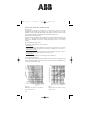
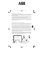
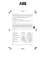
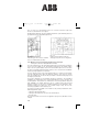
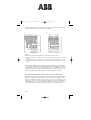
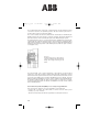
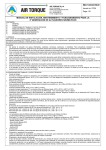
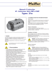
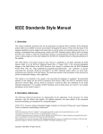
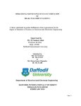
ABB_11_E_08
13.08.2007
9:07 Uhr
Seite 379
8. Switchgear and switchgear installations for
high voltage up to and including 52 kV (medium
voltage)
8.1 Switchgear apparatus (< 52 kV)
This voltage range is generally referred to as ”medium voltage”, even though the term
has not been standardized anywhere.
The principal terms relating to switchgear are defined in section 10.1.
8.1.1 Disconnectors
The classic design of the disconnector is the knife-contact disconnector (Fig. 8-1). It
has become less common with the increasing use of withdrawable circuit-breakers
and switch-disconnectors. This functional principle is now again becoming more
frequent in gas-insulated switchboard technology.
knife-contact
8
Fig. 8-1
Medium-voltage
disconnectors
The blades of knife-contact disconnectors installed in an upright or hanging position
must be prevented from moving by their own weight.
Disconnectors can be actuated manually and, in remotely operated installations, by
motor or compressed-air drives.
8.1.2 Switch-disconnectors
Switch-disconnectors are increasingly being used in distribution networks for
switching cables and overhead lines. Switch-disconnectors in connection with HRC
fuses are used for protection of smaller transformers.
Switch-disconnectors are switches that in their open position meet the conditions
specified for isolating distances. General purpose switches can make and break all
types of operating currents in fault-free operation and in the event of earth faults. They
can also make and conduct short-circuit currents.
a)
b)
Fig. 8-2
NAL type knife-contact switch-disconnector:
a) without and
b) with fuse assembly
379
Die ABB AG übernimmt keinerlei Verantwortung für eventuelle Fehler
oder Unvollständigkeiten in diesem Dokument.
Vervielfältigung - auch von Teilen - ist ohne vorherige schriftliche
Zustimmung durch die ABB AG verboten.
Copyright © 2007 by ABB AG, Mannheim
Alle Rechte vorbehalten.
ABB_11_E_08
13.08.2007
a)
9:07 Uhr
Seite 380
b)
Fig. 8-3
C4 rod-type switch-disconnector:
a) without fuse assembly b) with fuse assembly
Knife-contact switch-disconnectors as per figure 8-2 and rod-type switchdisconnectors as shown in figure 8-3 are actuated in two ways, depending on their
type:
a) ”Snap-action mechanism”, also referred to as toggle-spring mechanism. With this
type of operating mechanism, a spring is tensioned and released shortly before the
operating angle is completed and its release force actuates the main contact systems.
This is used for both closing and opening.
b) ”Stored-energy mechanism”. This mechanism has one spring for closing and a
second spring for opening. During the closing operation, the opening spring is
simultaneously tensioned and latched. The stored energy for the opening operation is
released by magnetic trips or the striker pin of the HRC fuse.
The rod-type switch-disconnector is particularly suitable for the design of compact
switchgears, because the knife-contact switch-disconnector requires a greater depth
for the switching zone because of the projecting contact blade in its open state. The
rod-type switch-disconnectors also enable very small phase spacings without phase
barriers.
8.1.3 Earthing switches
Earthing switches are installed in switchgears primarily near cable sealing ends, i.e.
before the main switching device. However, earthing switches are often specified also
for busbar earthing, for example in metering panels. If the main switching device is a
switch-disconnector, the earthing switch and the switch-disconnector will often be on
a common base frame (Fig. 8-4).
Fig. 8-4
Arrangement of
earthing switches
on a switchdisconnector base
frame
380
ABB_11_E_08
13.08.2007
9:07 Uhr
Seite 381
Every earthing switch must be capable of conducting its rated short-time current
without damage. ”Make-proof” earthing switches are also capable of making the
associated peak current at rated voltage. For safety reasons, make-proof earthing
switches are recommended with air-insulated switchgear because of possible faulty
actuations (DIN VDE 0101, Section 4.4). In gas-insulated switchgear, the earthing of a
feeder is often prepared by the earthing switch and completed by closing the circuitbreaker. In this case, a separate make-proof earthing switch is not required.
8.1.4 Recognizable switch position
Because disconnectors, switch-disconnectors and earthing switches are very
important to safety in the isolation of cables, lines and station components, there are
special requirements for their position indication. It is true that the switch contacts
themselves no longer need to be directly visible, but it is required that the switch
position be recognizable, i.e. that actuation of indicators or auxiliary switches must be
picked up directly at the switch contacts and not from a link in the force transmission
mechanism upstream from the operating spring (IEC 62271-102 (VDE 0671 Part 102)).
The load current flows in fuse links through narrow melt-out conductor bands, which
are arranged spirally in a sealed dry quartz sand filling in the interior of an extremely
thermally resistant ceramic pipe. The conductor bands are designed with a narrower
cross-section at many points to ensure that in the event of an overcurrent or shortcircuit current, a defined melting will occur at many points simultaneously. The
resulting arc voltage ensures current limiting interruption in case of high short-circuit
currents.
Fig. 8-5
Fuse base with fuse link
The cap-shaped end contacts of the HRC fuse link are picked up by the terminal
contacts of the fuse base. HRC fuse links can be fitted with indicators or striker pins,
which respond when the band-shaped conductors melt through. The striker pin is
required for mechanical tripping of the switching device when used in the switch/fuse
combination (IEC 62 271-105 (VDE 0671 Part 105)).
381
8
8.1.5 HRC fuse links (DIN VDE 0670 Part 4)
ABB_11_E_08
13.08.2007
9:07 Uhr
Seite 382
Characteristic current values for HRC fuse links:
Rated current
The majority of fuse links in operation have a rated current < 100 A. For special
applications with smaller service voltages (e.g. 12 kV), fuse links up to 315 A are
available. The associated melt-through times of the fusible conductors can be found in
the melting characteristics published by the manufacturers (Fig. 8-6).
Rated maximum breaking current
This value must be provided by the manufacturer of the fuse link. It is influenced by the
design for a specified rated current. When selecting fuse links for transformer
protection in distribution systems, the maximum breaking current is not a critical
quantity.
Rated minimum breaking current
Classification of fuse links into three categories
– Back-up fuses
Smallest breaking current (manufacturer’s information) in general at 2.5 to 3.5 times
rated current. Suitable for application in switch/fuse combinations. Very common!
– General purpose fuses
The smallest breaking current is that which results in melt-through after 1 hour or
more of exposure time (generally twice the rated current).
– Full-range fuses
Every current that results in a melt-through can be interrupted.
Melting time
seconds
Max. cut-off current kA (peak value)
minutes
Cut-off current characteristic
The maximum value of the current let-through by the fuse depends on its rated current
and the prospective short-circuit current of the system at the point of installation. Fig.
8-7 shows a characteristic field.
current in A
Fig. 8-6
Melting time in relation to overcurrent /
short-circuit current
382
Short-circuit current kA (eff.)
Fig. 8-7
Cut-off current in relation to shortcircuit current
ABB_11_E_08
13.08.2007
9:07 Uhr
Seite 383
Selecting fuse links for specific conditions
When protecting transformers and capacitors with fuses, the inrush currents must be
taken into account. When protecting transformers, selectivity is required by making
the melting times of low-voltage fuses and HRC fuses match to ensure that the lowvoltage fuses respond first.
In capacitor banks the rated current of the HRC fuse links should be at least 1.6 times
the rated current of the capacitors. Experience has demonstrated that this covers also
the influences of possible system harmonics and increased voltage.
When selecting fuse links for protection of high-voltage motors, the starting current
and the starting time of the motors must be taken into account. The frequency of startups must also not be neglected, if this is frequent enough to prevent the fuses from
cooling down between starts.
8.1.6 Is-Limiter® – the world’s fastest switching device
It is often not technically possible or not economical for the user to replace switchgear
and cable connections with new equipment with increased short-circuit current
capability. The implementation of Is-limiters when expanding existing installations and
constructing new installations reduces the possible short-circuit current and costs.
χ
A circuit-breaker does not provide protection against
impermissibly high peak shortcircuit currents, because it trips too slowly. Only the Is-limiter is capable of detecting
and limiting a short-circuit current in the initial rise, i.e. in less than one millisecond.
The maximum instantaneous current value that occurs remains well below the peak
value of the short-circuit current of the system.
The Is-limiter, like a fuse, is therefore a current-limiting switching device, which detects
and limits the short-circuit current in the initial rise (figure 8-8). The short-circuit current
through the Is-limiter is limited so quickly that it does not contribute in any way to the
peak value of the short-circuit current at the fault location.
a)
b)
i
126 kA
T1
io = i1 + i2
IK = 25 kA
i1
i = i1 + i2
63 kA
IK = 25 kA
i2
IK zul. = 25 kA
i m= i1 + i2
(25 kA x χ x 2)
i1
i2
t
Fig. 8-8
T2
Short-circuit breaking with Is-limiter
a) Current path
io Total current without Is-limiter
im Total current with Is-limiter
b) Single line diagram
383
8
The increasing requirements for energy throughout the world demand higher rated or
supplementary transformers and generators and tighter integration of the supply
systems. This can also result in the permissible short-circuit currents of the equipment
being exceeded and the equipment being dynamically or thermally destroyed.
ABB_11_E_08
13.08.2007
9:07 Uhr
Seite 384
In principle, the Is-limiter consists of an extremely fast switching device that can
conduct a high rated current but has only a low switching capacity, and a parallel
configured fuse with high breaking capacity (figure 8-9). To achieve the desired short
switching delay, a small charge is used as energy storage to interrupt the main
conductor. When the explosive charge has detonated, the current commutates to the
parallel fuse, where it is limited within 0.5 ms and then is finally interrupted at the next
voltage zero.
Fig. 8-9
Holder and insert of an Is-limiter
1
2
1 Insulating tube
2 Charge
3 Bursting bridge (main conductor)
4 Fuse
5 Pulse transformer
4
3
5
Depending on the voltage, the rated currents of Is-limiter inserts range up to 4,000 A
(and even up to 4,500 A at 0.75 kV) and they can be connected in parallel for higher
current levels.
Is-limiters are most commonly used (figure 8-10)
– in couplings,
– in connections between the public network and internal power supply systems
– in parallel with reactors,
(avoidance of copper losses and voltage drops at reactors)
– in transformer or generator feeders, and
– in outgoing feeder panels.
a)
T1
b)
T2
c)
G
Fig. 8-10
Example applications of Is-limiters
a) couplings, b) feeders, c) parallel circuits to reactors in incoming and outgoing
feeders
384
ABB_11_E_08
13.08.2007
9:07 Uhr
Seite 385
8.1.7 Circuit-breakers
There are still a number of ”small-oil-volume” circuit-breakers in use for rated voltages
up to 52 kV in systems, but for new installations only vacuum or SF6 circuit-breakers
are used.
Circuit-breakers can be stationary mounted or integrated into the panel in
withdrawable unit design with appropriate interlocking mechanisms.
Circuit-breakers must be capable of making and breaking all short-circuit and service
currents occurring at the operational site. See 10.4.3 for details. The testing conditions
for the corresponding verifications can be found in DIN VDE 0671 Part 100.
Vacuum circuit-breakers
Vacuum circuit-breakers of the VD4 type are available from the ABB production range
for short-circuit breaking currents up to 63 kA with rated currents from 400 to 4,000 A.
The VD4 range covers the voltage ranges of 12 kV, 17.5 kV, 24 kV and 36/40.5 kV.
Fig. 8-11 shows a vacuum circuit-breaker of the VD4 type in column design.
Fig. 8-11
8
Section of a vacuum circuit-breaker type VD4
for 12 kV, 2,000 A, 40 kA
1 Upper terminal
2 Vacuum interrupter
3 Cast resin enclosure
4 Lower terminal
5 Multi-contact
6 Piston
7 Contact pressure spring
8 Insulated actuating rod
9 Opening spring
10 Guide lever
11 Mechanism shaft
12 Release mechanism
13 Mechanism enclosure with stored-energy
spring mechanism
The components of the main current path (upper breaker terminal, vacuum interrupter,
lower terminal, etc.) are embedded in cast resin and thus completely enclosed by
insulating material. The concept of these embedded pole parts, in which the vacuum
interrupter forms a positive and non-positive unit with the entire pole, precludes
disruptive external influences on the switching element proper. The VD4 vacuum
circuit-breaker is therefore particularly suitable for construction of compact panels.
385
ABB_11_E_08
13.08.2007
9:08 Uhr
Seite 386
Figure 8-12 shows the VD4 circuit-breaker with isolating contact arms on the
withdrawable module frame for service in air-insulated panels of type UniGear ZS1.
Fig. 8-12
Vacuum circuit-breaker type VD4 for 12
kV as a withdrawable unit
Fig. 8-13 shows the most important components of a vacuum interrupter from the ABB
range in sectional view. All joints of the conducting path and of the external enclosure
are manufactured by brazing in vacuum furnaces with the aid of special hard solder.
This results in an extremely reliable and long-lasting seal.
Fig. 8-13
Partial section of a vacuum interrupter,
simplified schematic illustration
1 Insulator
2 Fixed contact
3 Moving contact
4 Metal bellows
5 Screen
6 Interrupter lid
7 Anti-rotation element
The contacts are a copper/chromium composite material, a copper base containing
evenly distributed fine-grained chromium particles, which has a good extinguishing
and arc-resistant response when switching short-circuit currents, and is also
distinguished by low-chopping current values when breaking small inductive currents.
386
ABB_11_E_08
13.08.2007
9:08 Uhr
Seite 387
Switching overvoltages
Switching overvoltages when switching inductive loads with vacuum circuit-breakers
have long been a subject of discussion. The introduction of copper/chromium as the
contact material has significantly reduced the occurrence of hazardous overvoltage
levels. To cover the residual risk, surge arresters based on metal oxide (MO) are
recommended for certain applications. Examples of such applications are:
– small motors (with starting current below about 600 A),
– small generators,
– reactor coils for power factor correction,
– dry-type transformers in industrial applications.
Only in special cases (e.g. furnace transformers) are supplementary RC circuits
required, preferably in the form of ZORC combinations (zinc oxide+R+C).
The travel of the moving contact between the open and closed positions in the
vacuum circuit-breaker is between 8 and 14 mm depending on the rated voltage. At
the end of the closing stroke, the energy for tensioning the contact pressure springs is
required. The relatively low total energy requirement for vacuum circuit-breakers is
generally provided by mechanical spring stored energy operating mechanisms, as with
the VD4 type. Tripping is initiated by magnetic releases or manually. The mechanical
operating mechanism of the VD4 circuit-breaker is always suitable for autoreclosing
(0 – t – CO).
Figure 8-14 shows a new operating mechanism system for the vacuum circuit-breaker
of type VM1.
1 Upper terminal
2 Vacuum interrupter
3 Cast resin enclosure
4 Lower terminal
5 Flexible connector
6 Contact pressure spring
7 Insulated actuating rod
8 Lever shaft
9 Sensor for switch position ON
10 Sensor for switch position OFF
11 ON coil
12 Permanent magnets
13 Magnet armature
14 OFF coil
15 Emergency manual switch-off
16 Mechanism enclosure
Fig. 8-14
Vacuum circuit-breaker type VM1 with magnetic actuator (compatible with type VD4)
387
8
Actuating systems
ABB_11_E_08
13.08.2007
9:08 Uhr
Seite 388
The movable contacts here are actuated by a permanent magnet mechanism with two
stable limit positions. The contact movements are initiated by current pulses to one
coil for each contact (approx. 100 Watt / 45 ms), generated by discharge of a
capacitor, i.e. with less energy than with the magnetic releases of the stored-energy
spring mechanism.
The release currents are exclusively controlled by electronic components (thyristors
and transistors). A fixed-programmed logic circuit coordinates the processes and
interlock conditions. The contact position is detected by sensors. The interface to the
automation system is through binary inputs and outputs.
Because of the extremely small number of individual parts, this actuating system offers
significant advantages in reliability, durability (up to 100,000 switching cycles) and
manufacturing costs.
The pole section (figure 8-14) with the vacuum interrupter moulded in epoxy resin has
optimum dielectric properties, permanent protection against external influences of all
types and because of the small number of parts, very little likelihood of faults
occurring. This eliminates the requirement for maintenance of this switching device
under standard operating conditions.
SF6-circuit-breakers
After its successful implementation in the range of transmission voltages (cf. section
10), SF6 has also become established in the medium-voltage range. The puffer type
arc-quenching principle, which was introduced first, provides an effective arcquenching gas flow by a mechanically driven piston. However, this requires high
energy driving systems. Hence self-blast arc-quenching systems of different types
were developed, where the relative movement between the gas and the arc is provided
by the arc itself.
The ABB SF6 circuit-breakers of type HD4 make use of a combination of these twodifferent arc-quenching principles (see figure 8-15). They cover the voltage range up to
24 kV, with short-circuit breaking currents up to 50 kA and service currents up to 4,000
A. The arc-quenching system applies the gas compressed in the lower chamber to
interrupt small currents with overvoltage factors < 2.5 p.u. even in the case of small
inductive currents. High short-circuit currents are interrupted by the self-blast effect
applying the pressure built up in the moving chamber by the arc energy.
Fig. 8-15:
SF6 circuit-breaker:
Functional principle of
the ”Autopuffer”
quenching system
388
1 Upper terminal
2 Main contact
3 Nozzle
4 Arcing contact
5 Nozzle pressure chamber
6 Valves
7 Lower chamber
8 Insulating enclosure
left: closed
right: open
ABB_11_E_08
13.08.2007
9:08 Uhr
Seite 389
8.1.8 Vacuum contactors
Vacuum contactors, in connection with HRC fuses, are particularly suitable for
operational switching of motors with very high switching frequency, e.g. medium
voltage motors for pumps, fans, compensators and capacitors. HRC fuses provide
protection for cables and circuit components in case of a short circuit. Vacuum
contactors have a life expectancy (electrical) of 1•106 operating cycles, and can handle
a switching frequency up to 1,200 on/off operations per hour. The vacuum contactors
of type VSC (figure 8-16) have rated voltages of 3.6 to 12 kV and a rated current of 400
A, and are suitable for switching of motors with ratings of 1,500 (3.6 kV) to 5,000 kW
(12 kV), and capacitors from 1,500 to 4,800 kVAr. This does not however take account
of whether suitable fuses are available to take advantage of the listed performance
ranges.
a)
b)
Fig. 8-16
8
Vacuum contactor, type
VSC, with magnetic actuator
a) Front view
b) Sectional view
8.2 Switchgear installations (≤ 52 kV)
8.2.1 Specifications for switchgear installations
This voltage range – generally referred to as medium voltage – covers switchgears and
controlgears in use and on the market that can be classified as per one of the two
following standards:
DIN VDE 0101 or
IEC 62271-200 (VDE 0671 Part 200)
8.2.2 Switchgear and controlgear DIN VDE 0101
Switchgears and controlgears to DIN VDE 0101 are designed to comply with fixed
minimum clearances of live components from one another, from earth potential and
from protecting barriers. They can basically be manufactured at the site where they will
be operated. Current-carrying capacity for service and short-circuit currents must be
verified by calculation (see also section 4). Type testing is not required.
When setting up these installations in electrical equipment rooms with restricted
accessibility, protection against accidental contact with live components, e.g. screens
or rails, is sufficient. The switchgear can also be designed with sheet metal walls and
doors (minimum height 180 cm) (cf. sections 4.5; 4.6 and 5.2). Reinforced wallboard
is also frequently encountered as a wall material. The switchgears can also be
completely enclosed for full protection for operation outside locked premises.
389
ABB_11_E_08
13.08.2007
9:09 Uhr
Seite 390
The use of insulating materials and intelligent design will allow smaller clearances,
particularly in the terminal zone of circuit-breakers and switch-disconnectors, than the
specified minimum clearances as per DIN VDE 0101 (cf. Table 4-12). A device of this
kind must be tested with connected conductors in the zone in which the permissible
minimum clearances are not met. This zone is referred to as the ”tested terminal zone”
(see DIN VDE 0101). It must be included in the user’s manual for the switching devices
with the main dimensions (figure 8-17).
Fig. 8-17
Tested terminal zone to DIN VDE 0101
M = Minimum clearance to DIN VDE 0101.
Here, the tested terminal zone = 200 mm.
Today, switchgears and controlgears to DIN VDE 0101 are mainly encountered in
individual installation design on site or are manufactured by smaller companies
without in-house test laboratories.
DIN VDE 0101 also includes basic specifications for the general design of a substation,
including the structural requirements. They are also applicable for the installation of
type-tested switchgear as per IEC 62271-200 (VDE 0671 Part 200).
8.2.3 Metal-enclosed switchgear and controlgear to IEC 62271-200 (VDE 0671
Part 200)
Metal-enclosed switchgear and controlgear are generally assembled from type-tested
panels these days. As per IEC 62271-200 (VDE 0671 Part 200) metal-enclosed
switchgear installations must be designed so that their insulation capacity, degree of
protection, current carrying capacity, switching capacity and mechanical function
conform to the requirements set by the testing provisions. This is verified by a type test
on a prototype panel. In addition, a routine test is made on every completed panel or
every transport unit.
Note: Together with IEC 62271-200 (VDE 0671 Part 200), the higher-order standard
IEC 60694 (VDE 0670 Part 1000) is always to be observed. Type-tested
switchgear installations with insulated enclosures are subject to IEC 60466.
However, there is no longer a corresponding European or German standard.
390
ABB_11_E_08
13.08.2007
9:09 Uhr
Seite 391
Rated voltage
The rated values for the insulation level of a switchgear installation must be selected
on the basis of the requirements of the system at the installation site from the selection
tables in IEC 60 694 (VDE 0670 Part 1000).
Table 10-1 (Section 10) shows the selection values for the range of rated voltages up
to 52 kV. The voltage values ”over the isolating distance” only apply for switching
devices with which the safety requirements for the open contacts of disconnectors
must be met.
Table 10-1 lists two value pairs that can be selected for the rated lightning impulse
voltage level for almost all rated voltages. The options correspond to the former
subdivision in list 1 and list 2.
When making the selection, the degree of danger from lightning and switching
overvoltages, the type of neutral treatment and, if applicable, the type of overvoltage
protection should be considered. The higher value pairs in each case are the ones to
be selected for installations and equipment exposed to atmospheric overvoltages, e.g.
by direct connection to overhead lines. The lower value pairs can be used for
installations that are not exposed to atmospheric overvoltages or are protected from
these overvoltages by arresters.
IEC 62271-200 covers both switchgear in which atmospheric air acts as the gaseous
insulation within the enclosures and also switchgear in which an insulating medium in
the form of a fluid other than the atmospheric air (e.g. SF6) is used (air-insulated:
AIS/gas-insulated: GIS).
Degree of protection for metal-enclosed switchgear and controlgear
The metallic and earthed enclosure protects personnel against approach to live
components and against contact with moving parts. It also protects the installation
against the penetration of foreign bodies. One of three different degrees of protection
may be selected for switchgear to IEC 62271-200. The difference is whether the
enclosure is suitable for repelling fingers or similar objects (IP 2X to IEC 60694,
Minimum requirements for metal-enclosed switchgear), rigid wires more than 2.5 mm
in diameter (IP 3X) or rigid wires more than 1 mm in diameter (IP 4X).
Compartments, accessibility and service continuity
Within the general term ”metal-enclosed”, distinctions were formerly made between
three categories – ”metal-clad”, ”compartmented” and ”cubicle” switchgear –
depending on the design of the internal compartmentalization. This structural
definition of compartmentalization has now been replaced in IEC 62271-200 by
classification according to the accessibility of the compartment with high voltage
components. Three of four classes are determined by how access is controlled, and
whether it is necessary to open the compartment in normal operation or only for
maintenance. Opening of all compartments which are only accessible by means of
tools is not part of normal operation. The fourth class describes non-accessible
compartments, such as those found in gas-insulated switchgear.
391
8
Insulating media
ABB_11_E_08
13.08.2007
9:09 Uhr
Seite 392
With a view to the accessibility of the compartments, the following distinctions are
made:
– ”Interlock-controlled accessible compartment”
Integral interlocks enable access to open the compartment for normal operation
and/or maintenance.
– ”Procedure-based accessible compartment”
Access to open the compartment for normal operation and/or maintenance is
regulated by a suitable procedure combined with locking.
– ”Tool-based accessible compartment”
The compartment can be opened with tools, but not for normal operation and/or
maintenance.
– ”Non-accessible compartment”
Categorization is then determined by the loss of service continuity, focusing on the
main switching device. The LSC categories result from the scope of switchgear
components to be taken out of service when a compartment is opened:
– LSC 1:
This category covers the lowest level of service continuity. It applies to an accessible
compartment in a panel which would require at least one further panel to be taken
out of service when it is opened. If a busbar compartment is opened, all the panels
in the relevant section must be de-energized.
– LSC 2A:
Category 2A stands for a panel which has to be taken completely out of service
when a compartment is opened. The panel has partition walls separating it from the
adjacent panels and at has least two compartments and an isolating distance.
– LSC 2B:
Category 2B provides the least restriction to service continuity and means that all
other panels in the installation and all cable termination compartments (including
that in the panel concerned) remain in operation when a compartment is opened. It
requires partition walls to the adjacent panels and at least three compartments and
two isolating distances per panel.
When a compartment has been opened, partitions and shutters to the adjacent
compartment or panel provide a degree of protection against live high voltage
components. The ”partition class” indicates whether the partition is metallic
throughout or contains parts of insulating material.
– Class PM:
”Partition of metal”; metallic shutters and partitions between live parts and an open
compartment.
– Class PI:
”Partition of insulating material”; discontinuity in the metallic partition/shutter
between live parts and an open compartment, which is covered by insulating
material.
Both partition classes provide the same protection against accidental contact for the
worker, but a metallic partition also screens off the electric field.
392
ABB_11_E_08
13.08.2007
9:09 Uhr
Seite 393
The decision on which of these installation categories is to be used in any specific
case is up to the user, with most attention paid to safety of personnel during
maintenance and cable work inside the metal-encelosed switchgear and controlgear.
Restricting the effects of faults is important only when the resistance of the
compartment walls to arcing has been verified and when the compartmentalization
forms a true potential separation (class PM).
Internal arcing
Internal short-circuit arcs during operation can occur by overvoltage, faulty insulation
or improper control. The test consists of inducing the arc with an ignition wire
connected over all three phases. The arc has temperatures of around 4.000 K in the
area of its footing points and around 10.000 K or more in the area of the arc column.
Immediately after the arc has been ignited, the gas in the immediate vicinity of the arc
heats up instantly, causing a very steep rise in pressure in the compartment
concerned. This pressure increase would continue to the load limit of the enclosure if
pressure relief vents were not built into it. The sealing covers or membranes of these
vents respond in ca. 5 to 15 ms and open the path to allow the heated gases to vent
(figure 8-18). This characteristic process is not determined only by the response time
of the pressure relief valves but it also results from the mechanical inertia of the heated
gas mass.
The maximum pressure reached is dependent on the volume of the compartment
where the fault occurs and on the magnitude of the short-circuit current. The greatest
quantity of heated gases is given off into the area around the switchgear during the
expansion phase. The pressure stress on the panel exceeds its high point as early as
about 15 ms, that of the building has reached its maximum stress after around 40 ms.
A powerful ejection of still heated gases of low density and glowing particles occurs in
the subsequent emission phase and in the thermal phase.
Fig. 8-18
Pressure development in the faulty panel
caused by internal arcing,
1 Compression phase (pressure build-up),
2 Expansion phase (pressure relief),
3 Emission phase (hot gases released),
4 Thermal phase (ejection of glowing
particles).
a) isochorous pressure rise,
b) opening of pressure relief valves.
393
8
All specialists are in basic agreement that manufacturers and users must make every
effort to prevent under all circumstances faults in switchgear installations in which
internal arcing occurs. However, it is also acknowledged that such faults cannot be
completely prevented in all cases. For this reason, it is expected that current
switchgear designs have been tested for response to internal arcing.
ABB_11_E_08
13.08.2007
9:09 Uhr
Seite 394
Guidelines for testing metal-enclosed switchgear for its response to internal arcing can
be found in Appendix A of IEC 62271-200 (VDE 0671 Part 200).
The specified test conditions require the internal arcing to be ignited with a thin ignition
wire in each compartment of the panel to be tested. The point of ignition and the
direction of energy flow are specified in such a way that the arc burns as long as
possible at the most distant location from the feeder. The short-circuit test plant
supplying the test object, which consists of at least two panels, must have sufficient
power to allow a short-circuit current as high as the rated short-time withstand current
to flow in three phases over the internal arcing during the agreed duration of the test
(recommended times 1.0, 0.5 or 0.1 s). This will cover the normal protection grading
times at full short-circuit current. With this short-circuit duration, the test result is
restricted to the question of whether the tested compartment withstands the stress
caused by the internal overpressure.
During the test, fabric indicators (black, cretonne or cotton-wool batiste) are stretched
vertically at a defined spacing on metal frames in front of the accessible walls of the
panels and horizontally at 2 m height above the zone where personnel would be when
operating the installation. With metal-enclosed switchgear, a distinction is made
between two degrees of accessibility which are possible at the point of installation:
Accessibility type A: For authorized personnel only
Accessibility type B: Unlimited access for the general public
The test conditions are also defined in accordance with these accessibility types
(figure 8-19). Different sides of a switchgear installation can have different degrees of
accessibility. The identification code for these uses the letters F (front), L (lateral) or R
(rear).
Accessibility – Type A
Accessibility – Type B
Fig. 8-19
Arrangement of the indicators for an arc fault test
h = height of switchgear; i = arrangement of indicators
394
ABB_11_E_08
13.08.2007
9:09 Uhr
Seite 395
On completion of the short-circuit test, the behaviour of the tested panels is recorded
on the basis of five criteria:
– Criterion 1:
Doors and covers remain closed. Deformations are acceptable if no part reaches the
indicators or walls.
– Criterion 2:
No fragmentation of the enclosure occurs within the duration of the test. Projections
of small parts, up to an individual mass of 60 g, are acceptable.
– Criterion 3:
Arcing does not cause holes in the accessible outer sides of the enclosure up to a
height of 2 m
– Criterion 4:
Horizontal and vertical indicators must not be ignited by hot gases. Permitted
exceptions: ignition by burning paint coatings, stickers or glowing particles.
– Criterion 5:
Earth connections remain effective, as demonstrated by visual inspection.
If the arc fault test is passed, for instance in the context of a type test, this is
documented by the designation IAC (”Internal Arc Classified”) on the type plate. The
confirmation of testing is supplemented by additional data such as the accessibility
type, indications of the accessible sides, the test current and duration.
There are further points to be considered over and above criterion 5 of the
assessment, as in the event of ejection of hot gases, the switchgear and controlgear
itself is not primarily relevant for the effects. Reflection from the ceilings and walls in
the emission phase and the thermal phase (figure 8-18) can divert the hot gases
coming from the pressure relief vents into zones accessible for personnel and cause
hazardous conditions there. The highest degree of damage also occurs during this
period inside the switchgear and controlgear. The ejection of very hot gas reaches its
most hazardous amount under the condition when caused by the direction of supply
(from below) the electromagnetic forces compel the arc to persist in the immediate
vicinity of the pressure relief vent. A panel type may be considered fully tested only
after this case has been considered.
Countermeasures for protection of the operating personnel against these effects can
be as simple as installing screens or discharge plates. At high short-circuit currents,
hot gas conduits with blow-out facilities using absorbers discharging into the
switchgear installation room are the perfect solution. However, even better results
without additional installations can be achieved if it is possible to limit the arc duration
to approximately 100 ms by appropriate trip times. Because the grading times of the
system protection do not generally allow such a short-term tripping of the feeder
circuit-breaker, additional sensors are required, such as the Ith-limiter. When one of the
pressure relief valves opens and there is simultaneous persistent short-circuit current,
it initiates an undelayed trip command to the feeder circuit-breaker. This quenches the
internal arc in less then 100 ms.
395
8
Additional information can be obtained in the form of high-speed camera pictures or
videos taken during the test, and these are therefore highly recommended.
ABB_11_E_08
13.08.2007
9:09 Uhr
Seite 396
The pressure load on walls, ceilings, doors and windows of the switchgear installation
room is the result of the gas ejection during the expansion phase (figure 8-18). The
withstand capability can generally not be verified by testing. All major manufacturers
provide calculation programs for determining the pressure development in the
switchgear installation compartment to find out whether pressure relief vents are
required for the installation room.
8.2.4 Metal-enclosed air-insulated switchgear and controlgear
to IEC 62271-200 (VDE 0671 Part 200)
Switchgear of this type currently has the largest market share worldwide
Metal-enclosed switchgear with three compartments
Figure 8-20 shows an example of such a metal-enclosed panel of type UniGear ZS1 to
LSC category 2B and partition class PM.
Fig. 8-20
A Busbar compartment
B Main switching device
compartment
C Cable termination compartment
D Low voltage compartment
1 Busbar
2 Isolating contacts
3 Circuit-breaker
4 Earthing switch
5 Current transformer
6 Voltage transformer
The circuit-breaker of this type of switchgear can be moved between the operating
position and test position when the door is closed. Because vacuum circuit-breakers
under normal operating conditions are almost maintenance-free, the door to the
circuit-breaker compartment can remain permanently closed. However, if it should be
necessary to remove the breaker from the panel, this can be done without problems
on a service truck that can be adjusted for height to the exact position.
Access to the cable sealing ends can be made much easier by removing the circuitbreaker and also removing the partition between compartments B and C.
396
ABB_11_E_08
13.08.2007
9:09 Uhr
Seite 397
Compartment C has room for the sealing ends of several parallel cables. Metallic oxide
arresters for overvoltage protection of inductive loads can also be installed here.
When the circuit-breaker is in the test position and the panel doors are closed, the
cables can be earthed via the permanently installed earthing switch (4, with shortcircuit making capacity). In order to check that the cables are off-circuit, voltage
indicator plugs can be inserted into test sockets at the front of the panels. The test
sockets are connected to the terminals of capacitive dividers, which are integrated in
the current transformers.
Instead of the vacuum circuit-breaker, an SF6 circuit-breaker of the HD4 type with
identical main dimensions can be installed in this switchgear type.
In addition to the standard switchgear panels with withdrawable circuit-breakers, there
are variations for sectionalizers, metering panels and panels with permanently installed
switch-disconnectors for substation power supply transformers. A further type
provides for the use of vacuum contactors. Figure 8-21 shows a sectional view of such
a contactor panel of type ZVC. One advantage of this panel is the small width of only
325 mm. Short-circuit protection is performed here by an HRC fuse integrated in the
contactor module. Double busbar installations are constructed from single busbar
panels in accordance with the two circuit-breaker method in back-to-back or front-tofront configurations (figure 8-22 with panel type UniGear ZS1). One highly interesting
variant for constricted spaces is the opportunity to accommodate two circuit-breakers
Fig. 8-21
Fig. 8-22
Panel type ZVC with
vacuum contactor on
withdrawable part
Double busbar switchgear installation with
UniGear type ZS1 panels in back-to-back
configuration
397
8
The UniGear ZS1 panel shown in figure 8-20 is designed for rated voltages up to 24 kV,
rated currents up to 4,000 A and rated short-time currents (3s) up to 50 kA. For 12 and
17.5 kV, the panel dimensions range between widths of 650/800/1000 mm and depths
of 1300/1350 mm, and for 24 kV between 800/1000 mm and 1500 mm respectively.
The uniform height is 2200 mm.
ABB_11_E_08
13.08.2007
9:09 Uhr
Seite 398
on two levels in a UniGear Double Level Panel with a width of only 750 mm for 12 kV
and up to 31.5 kA (900 mm for 50 kA) (figure 8-23).
Fig. 8-23
Two level panel configuration of type
UniGear Double Level
Metal-enclosed switchgear with one or two compartments
Figure 8-24 shows metal-enclosed switchgear of type ZS8 with one compartment in
accordance with LSC category 1 and partition class PI. They are available as panels
with permanently installed switch-disconnectors for switching cables and overhead
lines and with HRC fuses for protection of distribution transformers. The switchdisconnectors can be remote-controlled by a motor-operated mechanism. In the
circuit-breaker panels, the VD4 and VM1 vacuum circuit-breakers are withdrawable
units that can be moved when the panel door is closed.
a)
b)
Fig. 8-24
Panels of type ZS8:
a) Switch-disconnector panel
b) Switch-disconnector panel with HRC fuses
c) Circuit-breaker panel
398
c)
ABB_11_E_08
13.08.2007
9:10 Uhr
Seite 399
ZS8 panels are equipped with earthing switches (with short-circuit making capacity)
for feeder earthing. The earthing switches can only be closed when the switchdisconnector is open or the circuit-breaker withdrawable unit is in the disconnected
position. There is an insulating plate integrated in every panel, which slides into the
open break of the switch-disconnector or in front of the busbar-side isolating contacts
of the circuit-breaker panel. This assures protection against accidental approach to
live components during work in the panel, e.g. at the cable sealing ends. There are also
ZS8 panels with ”tee-off partitions” to LSC category 2A and partition class PM (figure
8-25). These panels have earthed metallic partitions, which separate the busbar
system from the areas of switching devices and cable terminals. The protection
against accidental contact with the isolating contacts installed in epoxy resin spouts in
these panels is provided by earthed metallic shutters that swing in front of the epoxy
resin spouts. The panel doors can only be opened after closing the protection shutter
in all ZS8 type switchgear.
Checking that the cables are off-circuit can be performed with conventional voltage
indicators or by using voltage indicator plugs at externally accessible test sockets.
Measurements using sockets require installation of capacitive divider devices in the
epoxy resin insulators of the switch-disconnector or in the current transformer of the
circuit-breaker panels.
Panel variations of the ZS8 series in addition to the switchgear with switchdisconnectors or circuit-breakers include sectionalizers, busbar risers and metering
panels.
Fig. 8-25
Switchgear
partition
type
ZS8
with
tee-off
399
8
All the panel variants in the ZS8 series can be mounted side by side in spite of their
different dimensions. The switch-disconnector panel can however also be supplied in
the same depth as the circuit-breaker panel. The most important dimensions of these
panels are widths of 600 or 650 mm for the switch-disconnector panel and 650 or 800
mm for the circuit-breaker panel. Depending on the ratings, the panel depths are
600/800/1000 or 1200 mm. The panel height is standardized at 1900 mm. The rated
data cover a voltage range up to 24 kV, busbar currents and tee-off currents with
circuit-breakers up to 1,250 A, tee-off currents with switch-disconnectors up to 630 A,
and short-time currents (3s) up to 25 kA.
ABB_11_E_08
13.08.2007
9:10 Uhr
Seite 400
Here, too, there is a special design for the use of vacuum contactors. Figure 8-26
shows a sectional view of such a panel.
Double busbar switchgear can also be implemented in this system with ZS8 panels in a
special back-to-back configuration (figure 8-27).
Fig. 8-26
ZS8 switchgear with contactor and HRC
fuses on a withdrawable assembly
Fig. 8-27
Double busbar installation with ZS8
switchgear in back-to-back configuration
8.2.5 Metal-enclosed gas-insulated switchgear and controlgear
switchgear to IEC 62271-200 (VDE 0671 Part 200)
The same standard as for the air-insulated switchgear and controlgear described in
section 8.2.4 also applies to the gas-insulated switchgear of the medium-voltage
range. The term ”gas-insulated” refers to the fact that atmospheric air is not used as
the gaseous insulating material inside the panels, i.e. the enclosure of the installation
must be gas-tight against the environment.
The gas currently used in most gas-insulated designs is a synthetic electronegative
gas, SF6, with almost three times the dielectric resistance of air. (See also section
16.3.) The insulating gas can also be nitrogen, helium or air dried for the purpose and
at a higher pressure level.
The decisive advantage of gas-insulated switchgear compared to an air-insulated
installation is its independence from environmental influences such as moisture, salt
fog and pollution. This results in less maintenance, increased operational safety and
high availability. The smaller dimensions due to compact design and increased
dielectric resistance of the gaseous insulating material are also advantages. Gasinsulated switchgear technology in the medium-voltage range has become
increasingly significant over the last 30 years.
The numerous designs available on the market can be generally classified into three
different application groups:
– switchgear with circuit-breakers
– switchgear with switch-disconnectors and circuit-breakers
– ring-main units
One technical solution for each of these application groups is described below as an
example.
400
ABB_11_E_08
13.08.2007
9:10 Uhr
Seite 401
Gas-insulated switchgear with circuit-breakers
Figure 8-28 shows a panel of type ZX1 (for 12 to 36 (40.5) kV) with the versatile options
offered by the advanced technology of these new switchgear designs.
The principles used for the application are:
– High-precision enclosure
– The gas-tight enclosure of the live components is manufactured from stainless steel
using laser technology for high-precision cutting and welding. This not only ensures
that the enclosure is gas-tight but also allows the panels to be mounted side by side
at site without problems.
b)
8
a)
Fig. 8-28
Metal-enclosed gas-insulated switchgear of type
ZX1 with single busbar system
a) Outgoing feeder panel, 630 A
b) Outgoing feeder panel, 1,250 A with 2
parallel cables and optional instrument
transformers
c) Incoming feeder panel, 2,500 A with 4
parallel cables and current and voltage
transformers
1 Density sensor
2 Circuit-breaker operating mechanism
3 Multifunctional protection and control unit
REF542 plus
4 3-position switch operating mechanism
5 3-position switch
6 Busbar
7 Pressure relief disk
8 Pressure relief duct
9 Toroidal-core current transformer
10 Cable plug
11 Cable socket
12 Measuring sockets for capacitive voltage
indicator system
13 Test socket
14 Circuit-breaker
15 Plasma deflector
SF6
c)
401
ABB_11_E_08
13.08.2007
9:10 Uhr
Seite 402
Vacuum switching technology
– The application of vacuum switching technology as the quenching principle of the
circuit-breaker meets a primary requirement for gas-insulated switchgear: the
interrupter unit must be maintenance-free. So far, this requirement is really only met
by vacuum interrupters, because of their low contact burn-off and their high
electrical durability. Gas-insulated switchgear for this voltage range with SF6 circuitbreakers is however also available.
Plug connector technology
– The application of plug-in technology is essential for ensuring short assembly times
when setting up installations. Several parallel cables can be connected to the
commercially available internal conical sockets in the baseplate of the core module.
The plug-in technology in the area of the busbar bushings is new but based on the
same technology as the cable connectors. These bushings designed as plug
connectors are the most important requirement for easy installation of the
completed panels. There are additional plug connectors in the supply lines for
auxiliary power and in the fibre-optic connections to the higher-order control
system, if present.
Sensors for measured quantities and states
– The combined current/voltage sensor has three functions. For current
measurement, it has a Rogowski coil, which gives a voltage signal that has a linear
dependency on the current and therefore can be used in a very broad current range
(e.g. to 1250 A in one type). This not only simplifies planning but also increases the
flexibility when modifying installations that are already operating.
– A high-resistance (200 MΩ) voltage divider is used as a voltage sensor. Two bellshaped screening electrodes ensure equal distribution of the electric field along the
resistance. The voltage signal captured at the subresistance of the divider is fed to
the bay control unit.
– The earth side of the two screening electrodes is simultaneously used as a
capacitive pick-off for voltage indication with standard commercial plugs. It is
connected to test sockets on the front of the panel to allow checking that the cables
are off-circuit independently of the functional availability of the bay control unit.
– The positions of the two switching devices and the ‘ready for switching’ indication
of the circuit-breaker mechanism are detected by inductive proximity sensors. A
temperature-compensated pressure sensor signals three pressure/density levels:
filling pressure at 20°C, lower operational pressure limit and pressure with internal
arcing. All sensor information goes directly to the bay control unit and is displayed
and processed there.
Digital bay control and protection unit
– The multifunctional bay control and protection unit REF542 plus is the base of the
intelligence and communications interface of the new switchgear (see also section
14).
It has the following functions:
– Local and remote actuation
– Display of switch positions, measured values and protection parameters
– Interlocking, internal and external
402
ABB_11_E_08
13.08.2007
9:10 Uhr
Seite 403
– Protection (all protective functions except for differential cable protection)
– Storage of events
– Information transmission to a higher-order control system
– Monitoring its own functions and the release and measurement circuits
– Disturbance recorder – recording time 5 s with sampling rate 1.2 kHZ
Personnel safety design
– In a switchgear system such as that of the ZX1 family, the occurrence of faults with
internal arcing is unlikely from the start. However, ZX1 panels offer complete
personnel protection in the event of internal arcing. In the case of a fault in the area
of the insulating gas, the housing is relieved from excessive stress by the response
of the pressure relief diaphragm, either directly into the switchgear room via the
plasma absorber or into a pressure release duct which runs horizontally across all
the panels and at the end of the installation releases the gas into the open air
through an outside wall or into the switchgear installation room via an absorber. The
response of the pressure sensor at 0.6 bar overpressure can be used to trip the
feeder circuit-breaker immediately without requiring additional components,
thereby reducing the arcing time to less than 100 ms. In the event of a fault in the
cable plug area, the pressure is also relieved into the pressure relief duct.
Here too, double busbar switchgear installations can be designed with the panels of
type ZX1, in accordance with the two-circuit-breaker method in back-to-back or frontto-front arrangement. Panel variants such as sectionalizers, busbar risers and
metering panels are also available.
The most important ratings are as follows: Rated voltage up to 36 (40.5) kV, rated
current up to 2,500 A and rated short-time current (3 s) up to 31.5 kA. The panel width
is 600 or 800 mm, depending on the current, the depth varies from 1300 to 1800 mm
depending on the cables connected, and the height is 2100 mm. The insulating gas is
SF6 at a rated filling pressure of 130 kPa.
The switchgear of type ZX2 (figure 8-29) is suitable for ”conventional” double busbar
systems that have two busbar systems for each panel. This switchgear has the same
advanced features as described for switchgear of type ZX1.
The technical data implemented to date include the rated voltage of up to 36 (40.5) kV,
rated current up to 2,500 A and rated short-time current (3 s) up to 40 kA. Here too, the
panel width is 600 or 800 mm, depending on the current, the depth is 1760 mm and
the height is 2300 mm. The insulating gas is SF6 at a rated filling pressure of 130 kPa.
403
8
– Faults in the sequence of actuation of circuit-breaker and disconnector/earthing
switch function of the transfer switch are prevented by interlocking in the control
unit. The earthing process can be automatically run as a programmed sequence
while retaining the ”five rules of safety”. Any required protective functions can be
installed as software before delivery. Software changes can be made on site at any
time with a laptop computer. Parameter changes can be made by pressing buttons
on the device itself.
ABB_11_E_08
13.08.2007
9:10 Uhr
Seite 404
Single busbar switchgear in the ZX2 design can also be used without the rear busbar
system to make full use of the advanced technical data.
a)
b)
Fig. 8-29
Metal-enclosed gas-insulated switchgear with double busbar, type ZX2
a) Incoming feeder panel, 2,000 A, with 4 parallel cables and current and voltage
sensors
b) Incoming feeder panel, 2,000 A, for 4 parallel cables, with conventional control
equipment: current and voltage transformers with process variables of 1 A and
100 V
In both the ZX2 and ZX1 series, an additional double panel with two outgoing feeders
is now available, requiring a width of only 400 mm per feeder for applications up to 24
kV and 630 A at 25 kA. These double panels leave the manufacturer’s works as
completely tested units and are connected directly to the adjacent panels at site
without any additional gas work, using the tried and tested plug-in technology.
Gas-insulated switchgear with switch-disconnectors and circuit-breakers
Gas-insulated switchgear technology is becoming a subject of increasing interest for
distribution systems and smaller industrial consumers. Because the high performance
data of the installations described in the previous section are not required, special
switchgear series have been developed for this application. A major characteristic of
this application is the use of switch-disconnectors for feeders with cables and
overhead lines and in combination with fuses for protection of small transformers.
404
ABB_11_E_08
13.08.2007
9:11 Uhr
Seite 405
Figure 8-26 shows cross-sections of variants from the ZX0 switchgear series in block
design. SF6 is used as the insulating gas and quenching medium for the switchdisconnectors for all rated voltages.
The switch-disconnectors integrated into the panels as three position switches include
the function of the earthing switch for the feeder. The contact blades are actuated by the
same mechanism with one actuating shaft for each function. The combination device as
a switch-disconnector meets the same requirements as a switch-disconnector tested
and manufactured as a single unit as per IEC 60265-1 (VDE 0670 Part 301). The
requirements of IEC 62271-200 (VDE 0671 Part 102) apply for the earthing function (with
short-circuit current-making capacity).
b)
c)
8
a)
Fig. 8-30
Metal-enclosed gas-insulated switchgear system type ZX0
in block design
a) Circuit-breaker panel for outgoing feeder currents of
630/800 A
b) Circuit-breaker panel for incoming feeder current 1,250 A
with integrated current and voltage transformers
c) Switch-disconnector panel
d) Switch-disconnector panel with fuses
d)
In order to check that the cables are off-circuit before earthing, voltage indicator plugs
can be inserted into test sockets at the front of the panels. These sockets are
connected to the taps of field grading electrodes inside the cable-plug bushings.
405
ABB_11_E_08
13.08.2007
9:11 Uhr
Seite 406
The circuit-breaker panels of this type of switchgear have vacuum interrupters with a
cast resin enclosure as arc-quenching systems. This also forms the pivot of the 3position switch for disconnecting and earthing.
The connected cables are therefore earthed via the circuit-breakers. The REF542 plus
digital protection and control unit also controls the actuation, interlocking, display and
protection functions in the circuit-breaker panel of the ZX0 switchgear system.
The ZX0 switchgear series as a compact all-rounder is available in the block design
variants with up to 6 panels grouped together to form a single gas compartment either
with manual mechanisms or electrical actuation, and as a variant with individual panel
partitioning and manual operation of all switching devices with the option of remote
control (figure 8-31).
Fig. 8-31
Circuit-breaker panel of type ZX0 for
1,250 A in individual panel partitioning
design with voltage metering at the
feeder
The technical data of the compact switchgear of type ZX0 are as follows: Rated
voltage up to 24 kV, rated current for busbar and feeder with circuit-breaker 1,250 A
and for feeder with 3-position switch-disconnector 630 A, and rated short-time current
(3 s) 25 kA. The insulating gas is SF6 with a rated filling pressure of 130 kPa. The panel
widths are 400 mm and 600 mm for feeder currents > 800 A and for individual panels;
the height is 2100 mm (2250 mm when increased space is required for secondary
systems) and the panel depths are 850 mm and 1000 mm for feeder currents > 800 A
and for individual panels.
Gas-insulated ring-main units (RMUs) for secondary energy distribution
There are two basic designs in use for the application of ring-main units:
– Systems with a common gas volume inside a common enclosure with a preset
number (e.g. 3 or 4) of feeders
– Panels mounted side by side with the opportunity for subsequent extension
406
ABB_11_E_08
13.08.2007
9:11 Uhr
Seite 407
Figure 8-32 shows such systems of type SafeRing with common enclosures for all
three feeders and the possibility of extension in type SafePlus.
a)
b)
8
Fig. 8-32
Elevations of ring-main units
a) Ring-main unit of type SafeRing
b) Ring-main unit of type SafePlus
SF6-switch-disconnectors are also used here to switch the connected cables and
overhead lines. For protection of transformers, either a vacuum circuit-breaker with
electronic protection (configuration CCV, figure 8-32a) or a switch-disconnector in
combination with HRC fuses (configuration CCF, same dimensions as CCV) can be
supplied.
Every panel has an earthing switch with specified making capacity to earth the
connected cables. In order to check that the cables are off-circuit before earthing,
voltage indicator plugs can be inserted into test sockets at the front of the panels.
These sockets are connected to capacitive pick-offs on the cable plug bushings.
The switch-disconnectors and circuit-breakers of the switchgear can be remotely
actuated with motor-operated mechanisms.
The technical limit data and dimensions of the SafeRing ring-main unit are as follows:
Rated voltage up to 24 kV, rated current for the C panel 630 A, for the F panel in
accordance with the fuse current, and for the V panel 200 A. Rated short-time current
(3 s) up to 21 kA for the C and V panels; F panel with limitation by HRC fuse. The
insulating gas is SF6 with a rated filling pressure of 130 kPa. The dimensions are
dependent on the number of panels per unit: widths are 696 mm (2 panels), 1021 mm
(3 panels) and 1346 mm (4 panels). The heights in the same order are 622, 947 and
1272 mm, and the depths 663, 983 and 1313 mm.
407
ABB_11_E_08
13.08.2007
9:11 Uhr
Seite 408
8.2.6 Control systems for medium voltage switchgear
Conventional secondary technology
A wide range of devices for protection, control and monitoring tasks is available for
conventional secondary technology in medium voltage switchgear installations. The
planning engineer selects the required units and combines them into one installation.
The output variables from the encoders are predominantly standardized to 1 A for
current and 100 V for voltage.
The information on measured values, switchgear status and fault messages is
transmitted through parallel wiring from the various medium voltage panels to a main
control desk or a telecontrol system. Records, data storage, graphical measured value
processing, help information when faults occur and self-monitoring functions are not
possible with this technology.
Microprocessor control systems
The implementation of digital system designed for the requirements of medium voltage
networks allows a number of much more powerful solutions at moderate expense. A
system of this type is divided into the bay level, the switchgear level and the control
room level (see also section 14.4).
At the bay level autonomously operating, modular and multifunctional devices that can
be adapted for the required protection, control and regulating tasks by appropriate
software are used. These monitoring devices are installed directly in the low voltage
compartments of the medium voltage panels. Here, all measured values, switch
positions and messages from the panels are acquired, processed and sent over a
serial (unified) interface. The device, which operates independently of the next
hierarchical level, combines the protective functions, the switching position display,
the measured value display and the local operation of the switchgear, which is
protected against maloperation, in one single housing. Its modular design makes it
adaptable for the panel-specific protection tasks and selectively or in combination it
controls functions such as motor protection, overcurrent definite-time protection,
overvoltage and undervoltage protection, earth fault detection, distance protection,
differential protection and disturbance recording. It has comprehensive selfmonitoring functions and also allows events to be sorted by time with real-time
stamping.
The multifunctional protection and control unit REF542 plus is a device of this type. It
can optionally be implemented autonomously for one panel only or integrated into a
higher-order automation system.
408
ABB_11_E_08
13.08.2007
9:11 Uhr
Seite 409
8.3 Terminal connections for medium voltage switchgear
8.3.1 Fully insulated transformer link with cables
Plastic-insulated cables and fully insulated (plug-in) cable terminals provide a number
of operational improvements in substation design when consistently used at the
interfaces between cables and station components. The key component for a new
type of cable link, as shown in figure 8-33, between the power transformer and the
switchgear installation is a multiple transformer terminal to figure 8-34 for four parallel
power cables. The multiple terminal is designed for a voltage of up to 36 kV and
enables currents of up to 3,150 A. The module can be retrofitted to all power
transformers. In addition to the operational advantages, this technology offers savings
because the transformer no longer requires a cable rack. For more information on plug
connectors for power cables, see section 13.2.8.
2
1
8
3
4
Fig. 8-33
Substation design with fully insulated cable link to the transformer
1 Multiple transformer terminal, 2 Substation building, 3 Switchgear, 4 Cable link in a
protective conduit
Fig. 8-34
Multiple transformer terminal
a) Elevation
b) Sectional view
1 Cable plug
2 Cast resin body with sockets
3 Metal casing
4 Conductor bar
5 Contact system
6 Transformer housing
7 Control shield
409
ABB_11_E_08
13.08.2007
9:11 Uhr
Seite 410
8.3.2 Solid-insulated bar connection
An option for making bar connections with low space requirements is to use
prefabricated epoxy resin-insulated capacitor-controlled single-phase conductors.
They are available for service voltages of up to 72.5 kV and for operating currents of
up to 5,000 A.
Design of the bar system
The preferred conductor material is an aluminium alloy with high mechanical strength
and low weight. A high voltage coating is first applied to the entire surface of the circular
or tubular conductor, and the appropriate insulation for the voltage level, consisting of
paper and a special cast resin impregnation, is applied to that (figure 8-35), with
capacitive control provided by conducting layers at the ends. The covering layer at earth
potential is fully embedded in the insulation. For outdoor use the bars are also enclosed
in a protective tube of aluminium or a flexible metal hose. The space between the bar
itself and the protective cover is then filled with cast resin.
a)
b)
c)
Fig. 8-35
Arrangement of a solid-insulated conductor bar for indoor use
a) Connecting bar between two switchgear sections with a wall opening
b) Connecting bar between two switchgear sections with cast resin-insulated,
capacitively controlled joint
c) Inner cone plug for connection to gas-insulated switchgear
The bars are manufactured in sections of up to 12 m in length. Single or multiple bends
are available as required made to fit the assembly and connection dimensions. The
bars are connected rigidly or flexibly to the devices or panels with screw or plug-type
terminals. Individual lengths are joined with special insulating cylinders. The
recommended phase clearances, e.g. 200–300 mm at 2,500 A, correspond to the
phase spacings of the switchgear. Standard support structures and clamps withstand
the short-circuit forces. The earth connections comply with the relevant specifications.
410