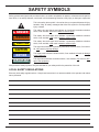
1
HS6000
MOUNTED
HYDRAULIC COMPACTOR
Safety, Operation and Maintenance
USER'S MANUAL
© 2010 Stanley Black & Decker, Inc.
New Britain, CT 06053
U.S.A.
65765 1/2014 Ver 6
TABLE OF CONTENTS
CERTIFICATE OF CONFORMITY............................................................................................................................. 4
SAFETY SYMBOLS.................................................................................................................................................... 5
SAFETY PRECAUTIONS........................................................................................................................................... 6
TOOL STICKERS & TAGS......................................................................................................................................... 7
OPERATION............................................................................................................................................................... 8
PREOPERATION PROCEDURES........................................................................................................................ 8
DAILY MAINTENANCE CHECKS ......................................................................................................................... 8
PRE-INSTALLATION INSTRUCTIONS................................................................................................................. 8
LOW-TEMPERATURE WARM-UP PROCEDURE................................................................................................ 8
GENERAL INSTRUCTIONS.................................................................................................................................. 9
COMPACTION....................................................................................................................................................... 9
GENERAL.............................................................................................................................................................. 9
SLOPE TECHNIQUE............................................................................................................................................. 9
SOIL TESTING...................................................................................................................................................... 9
DRIVING.............................................................................................................................................................. 10
TROUBLESHOOTING...............................................................................................................................................11
FLOW TEST PROCEDURES................................................................................................................................... 12
DEFINITION OF TERMS.......................................................................................................................................... 14
SPECIFICATIONS.................................................................................................................................................... 15
TORQUE TABLE...................................................................................................................................................... 15
HS6008F PARTS ILLUSTRATION........................................................................................................................... 16
HS6008F PARTS LIST............................................................................................................................................. 17
HS6019F, HS6026, HS6027 & HS6100 PARTS ILLUSTRATION............................................................................ 18
HS6019F, HS6026, HS6027 & HS6100 PARTS LIST.............................................................................................. 19
IMPORTANT
To fill out a Product Warranty Recording form, and for information on your warranty,
visit Stanleyhydraulic.com and select the Warranty tab.
(NOTE: The warranty recording form must be submitted to validate the warranty).
SERVICING THE STANLEY HYDRAULIC compactor. This manual contains safety, operation, and routine
maintenance instructions. Stanley Hydraulic Tools recommends that servicing of hydraulic tools, other
than routine maintenance, must be performed by an authorized and certified dealer. Please read the following warning.
WARNING
SERIOUS INJURY OR DEATH COULD RESULT FROM THE IMPROPER REPAIR OR SERVICE OF THIS TOOL.
REPAIRS AND / OR SERVICE TO THIS TOOL MUST ONLY BE
DONE BY AN AUTHORIZED AND CERTIFIED DEALER.
For the nearest authorized and certified dealer, call Stanley Hydraulic Tools at the number listed on the
back of this manual and ask for a Customer Service Representative.
3
DECLARATION OF CONFORMITY
DECLARATION OF CONFORMITY
ÜBEREINSTIMMUNGS-ERKLARUNG
DECLARATION DE CONFORMITE CEE
DECLARACION DE CONFORMIDAD
DICHIARAZIONE DI CONFORMITA
Hydraulic Tools
______________________________________________________________________
I, the undersigned:
Ich, der Unterzeichnende:
Je soussigné:
El abajo firmante:
lo sottoscritto:
Weisbeck, Andy
Surname and First names/Familiennname und Vornamen/Nom et prénom/Nombre y apellido/Cognome e nome
hereby declare that the equipment specified hereunder:
bestätige hiermit, daß erklaren Produkt genannten Werk oder Gerät:
déclare que l’équipement visé ci-dessous:
Por la presente declaro que el equipo se especifica a continuación:
Dichiaro che le apparecchiature specificate di seguito:
1.
Hydraulic Powered Compaction Machine
Category:
Kategorie:
Catégorie:
Categoria:
Categoria:
2.
Make/Marke/Marque/Marca/Marca
Stanley
3.
Type/Typ/Type/Tipo/Tipo:
HS3000, HS6000, HS8000, HS11000, HS22000
4.
Serial number of equipment:
Seriennummer des Geräts:
Numéro de série de l’équipement:
Numero de serie del equipo:
Matricola dell´attrezzatura:
5.
Mass/Masse/Masse/Masa/Massa
All
168/998 kg
Has been manufactured in conformity with
Wurde hergestellt in Übereinstimmung mit
Est fabriqué conformément
Ha sido fabricado de acuerdo con
E’ stata costruita in conformitá con
Directive/Standards
Richtlinie/Standards
Directives/Normes
Directriz/Los Normas
Direttiva/Norme
No.
Nr
Numéro
No
n.
Approved body
Prüfung durch
Organisme agréé
Aprobado
Collaudato
EN ISO
EN ISO
Machinery Directive
12100-1:2009
12100-2:2009
2006/42/EC:2006
Self
6.
Special Provisions:
None
Spezielle Bestimmungen:
Dispositions particulières:
Provisiones especiales:
Disposizioni speciali:
8.
Representative in the Union: Patrick Vervier, Stanley Dubuis 17-19, rue Jules Berthonneau-BP 3406 41034 Blois Cedex, France.
Vertreter in der Union/Représentant dans l’union/Representante en la Union/Rappresentante presso l’Unione
Done at/Ort/Fait à/Dado en/Fatto a Stanley Hydraulic Tools, Milwaukie, Oregon USA
Signature/Unterschrift/Signature/Firma/Firma
Position/Position/Fonction/Cargo/Posizione
Engineering Manager
4
1/6/2011
Date/Datum/le/Fecha/Data
1-6-11
SAFETY SYMBOLS
Safety symbols and signal words, as shown below, are used to emphasize all operator, maintenance and repair actions which, if not strictly followed, could result in a life-threatening situation, bodily injury or damage to equipment.
This is the safety alert symbol. It is used to alert you to potential personal injury
hazards. Obey all safety messages that follow this symbol to avoid possible
injury or death.
DANGER
This safety alert and signal word indicate an imminently hazardous situation
which, if not avoided, will result in death or serious injury.
WARNING
This safety alert and signal word indicate a potentially hazardous situation
which, if not avoided, could result in death or serious injury.
CAUTION
This safety alert and signal word indicate a potentially hazardous situation
which, if not avoided, could result in death or serious injury.
CAUTION
This signal word indicates a potentially hazardous situation which, if not avoided, may result in property damage.
NOTICE
This signal word indicates a situation which, if not avoided, will result in damage
to the equipment.
IMPORTANT
This signal word indicates a situation which, if not avoided, may result in damage to the equipment.
Always observe safety symbols. They are included for your safety and for the protection of the tool.
LOCAL SAFETY REGULATIONS
Enter any local safety regulations here. Keep these instructions in an area accessible to the operator and maintenance personnel.
5
SAFETY PRECAUTIONS
Tool operators and maintenance personnel must always comply with the safety precautions given in this manual and on the stickers and tags attached to the tool and hose.
These safety precautions are given for your safety. Review them carefully before operating the tool and before performing general maintenance or repairs.
Supervising personnel should develop additional precautions relating to the specific work
area and local safety regulations. If so, place the added precautions in the space provided in this manual.
The HS6008/6019 Mounted Hydraulic Compactor’s will provide safe and dependable
service if operated in accordance with the instructions given in this manual. Read and
understand this manual and any stickers and tags attached to the tool and hoses before
operation. Failure to do so could result in personal injury or equipment damage.
Check the rule and regulations at your location. The rules might include an employer's
work safety program. Regulations may identify hazards such as working around utility
supply lines or hazardous slopes.
BE THOROUGHLY TRAINED BEFORE OPERATING THE UNIT ALONE
• Operator training must start in an area without bystanders and use all the controls until he/she can control the machine
fully under the conditions of the work area.
• When learning to operate a machine, do so at a slow pace.
KNOW THE WORK CONDITIONS
• The operator must know any prohibited uses or work areas for the machine. For example, excessive slopes and poor
or dangerous terrain conditions must be avoided.
OBEY SAFETY RULES
• Replace all faulty or leaking hydraulic hoses or fittings before further operation.
• Always operate the compactor with backhoe outriggers firmly on the surface. The compactor weighs more than the
bucket. Position the compactor with caution.
• Travel with the compactor in full tuck (transport) position only.
• Never operate with any person near the compactor or between the compactor and operator.
• Operate the compactor in properly shored trenches and excavations. Do not allow personnel to work in the excavation
near compactor operation.
• Make sure all controls (levers and pedals) are in the NEUTRAL position before starting the carrier.
• Wear safety eye protection, hard hat, and safety foot protection while operating the compactor.
• Operate the carrier or compactor from the operator's seat ONLY. Make sure the seat belt is securely fastened before
activating any controls.
• Make certain that no other personnel are within the arc prescribed by the movement of the stabilizers, front bucket or
backhoe boom.
• Keep hands and feet on the controls at all times when the machine is running.
• Before leaving the operator's seat, always lower the loader arms and the backhoe boom.
• NEVER leave the machine with the engine running. ALWAYS ENGAGE THE PARKING BRAKE.
• Stop the engine before attempting to make any repairs or adjustments to either the carrier or compactor.
• To avoid personal injury or equipment damage, all tool repair, maintenance and service must only be performed by
authorized and properly trained personnel.
6
TOOL STICKERS & TAGS
47351
Composit Warning
29609
CE Spec Plate
(HS6019 Only)
29610
CE Spec Plate
(HS6008 Only)
HS6000
372083
Model Decal
47352
Lift Point Decal
19276
GPM Decal
09163
Stanley Logo Decal
7
OPERATION
Be sure the fluid and filter in the hydraulic system are
clean.
PREOPERATION PROCEDURES
When tightening pipe threads, be careful that any sealant used (Teflon ® tape, etc.) does not enter the hydraulic
system. Foreign matter introduced into the system may
damage hydraulic valves, motors and pumps.
DAILY MAINTENANCE CHECKS
Check for loose or missing fasteners. Tighten or replace as
needed. Refer to Torque Specifications in the Specification
section of this manual.
Follow instructions to install the Stanley priority valve in the
carrier hydraulic system. the warranty is in effect only if the
valve and compactor are installed as outlined in the valve
kit installation instructions. Major modifications or equipment substitution will cause the warranty to be void unless
prior engineering approval has been granted by Stanley
Hydraulic Tools.
Check to be certain that the flow control valve on the carrier
is set to the proper flow for the compactor. Refer to the
Specification section of this manual.
Check shock mounts for cracks or tears. Rotate shock
mounts 180° when fatigue tears begin to show at top outer
crease of the shock mount. This will prolong the life of the
shock mount.
The Stanley priority valve is a metering (to the hydraulic
tool) pressure compensating valve that controls the flow to
the attachment and gives the primary system (i.e. backhoe
functions) full operating pressure. Diverter valves or simple
flow control valves will not perform all of these required
functions.
Check for abrasion and hydraulic leaks at fittings and
hoses. Replace defective hoses and fittings. Adjust hoses
and tighten fittings so the hoses do not deflect into contact
with structure during use.
Note:
On carriers where priority valves are not used, check
with your local Stanley distributor for an adapter kit to
equip your carrier for a specific model of compactor.
WARNING
DO NOT USE BARE HANDS TO CHECK OR
SEARCH FOR HYDRAULIC LEAKS AROUND
HOSES AND FITTINGS. PINHOLE LEAKS CAN
PENETRATE THE SKIN. TO INSPECT FOR
LEAKS, DEPRESSURIZE THE SYSTEM, CLEAN
AROUND SUSPECTED AREA, REPRESSURIZE
THE SYSTEM, AND VISUALLY CHECK FOR
LEAKS.
LOW-TEMPERATURE WARM-UP PROCEDURE
When the weather gets cold, the shock mounts on compactors can become stiff. In severe weather, where the
ambient temperature is below freezing for extended periods, shock mounts can even become brittle. Therefore, it
is necessary to warm the shock mounts prior to using the
compactor. To warm the shock mounts follow these steps:
Lubricate bearings with two pumps of grease every 40
hours of operation. A greasing location is provided in both
bearing carriers.
1. After starting the carrier, warm up the system until hydraulic lines are warm to the touch.
Inspect pins and bushings for correct fit and lubrication.
2. With the carrier at idle, place the compactor flat on the
ground, and using a slight down pressure to keep the compactor in place, turn the compactor on. DO NOT place a
load on the compactor during this procedure.
Check level of hydraulic reservoir on carrier.
Make certain that quick couplers are fully engaged and leak
free.
3. When the ambient temperature is below freezing, the
compactor should be operated on the ground with a slight
down pressure (no load) for at least one minute before putting it to work.
PRE-INSTALLATION INSTRUCTIONS
Test the carrier hydraulic system to verify that the system
is operating at the manufacturer's specified capacity and
pressure ratings.
8
OPERATION
With a standard baseplate, the compactor is held with
full down pressure for no more than 5-10 seconds. The
application pattern should always begin next to a bank or
footing and at the previously compacted area. When the
maximum attainable density for that particular soil condition
is reached, a slight increase in vibration will be felt by the
operator. This increase in vibration is in no way harmful to
the tractor, and indicates that the soil will not compress any
further. In fact, additional time in that location may actually
loosen the soil previously compacted.
IMPORTANT
DO NOT SUSPEND THE COMPACTOR IN THE AIR DURING
THE WARM-UP PROCEDURE.
THE COMPACTOR MUST BE PLACED FLAT ON THE
GROUND WITH A VERY SLIGHT DOWN PRESSURE TO
KEEP IT IN PLACE. WHEN AMBIENT TEMPERATURES
ARE BELOW FREEZING, SUSPENDING THE COMPACTOR
IN THE AIR WITHOUT FIRST WARMING IT UP MAY CAUSE
THE SHOCK MOUNTS TO CRACK.
Work as much area as possible from one position and
overlap each compacted section slightly. The vibration
frequency has been chosen to give maximum efficiency in
granular soils using lifts of 2 to 4 feet. The closer the width
of the trench is to the width of the compactor, the higher the
delivered compactive effort.
FAILURE TO FOLLOW THESE PROCEDURES WILL VOID
COMPACTOR SHOCK MOUNT WARRANTY.
GENERAL INSTRUCTIONS
The compactor is a device that uses available force to
the best advantage. The DYNAMIC FORCE of the mass
weight assembly, turning at a high rpm, produces a vibratory force, and with controlled placement, an impact force.
The DOWN PRESSURE of the carrier on the compactor
gives a high static pressure which assists in the compaction or driving. The vibration frequency is controlled by the
hydraulic flow input to the compactor and is optimized for
use in granular soils. The rate and density of compaction
depends on such factors as moisture content of the soil,
condition of the compactor and carrier, and the skill of the
operator.
It is necessary to turn the compactor OFF when being
transported or sitting idle. Should the running compactor
be placed on a hard surface without down pressure, the
unit and the carrier will vibrate excessively. Down pressure
transmits the vibration to the soil; neutral pressure will rattle
the whole carrier assembly.
SLOPE TECHNIQUE
This method of compaction is of primary interest to a
pipeline contractor seeking high production and efficient
equipment utilization. The fill material is placed at one end
of the trench and allowed to seek its own angle of repose.
Compaction is begun on this angle above, but still near, the
top of the pipe. All fill material is backfilled to this angle and
the compactor is worked up and down the slope. Backfilling, compaction, and resurfacing can be done very shortly
after the pipe is in place.
NOTICE
Efficient compactor performance is directly related to the
flow rate specified. A higher flow rate does not improve
performance. It results in fluid overheating, and contributes
to early bearing failure. A lower flow rate causes reduced
compaction performance.
SOIL TESTING
Compaction density specifications are based on soil samples of a set moisture content and soil composition. Changing weather conditions, for example, can alter the moisture
content of the fill being used, and may make meeting the
specifications impossible. It is imperative that frequent and
reliable tests be conducted during application of the compactor to determine the maximum lift that can be used and
still provide the required density. It is important that lifts in
excess of the established test results NOT be used if the
required density is to be achieved and maintained.
The rate of compaction to a 95% Modified Proctor in
granular soils is approximately 25 cubic yards per hour for
the HS6000. This figure is variable and depends on such
factors as moisture content of the soil, condition of the compactor and carrier and the skill of the operator.
COMPACTION
GENERAL
The following instructions are very important to the proper
performance of the compactor and the attainment of the
specified compaction density.
9
OPERATION
DRIVING
Many driving jobs can be done with the compactor. Timber
sheeting, steel and aluminum sheeting, H and I-beams,
soldier piles and guard rail posts. The compactor will drive
these materials in most soil conditions, except solid rock or
soil with a very high clay content.
One note of caution; the forces generated and the methods used while driving with a vibratory device preclude the
calculation of "bearing loads" for a piling or sheet of material. DO NOT USE THE COMPACTOR IN APPLICATIONS
WHERE A BEARING LOAD IS SPECIFIED.
The compactor is placed on the object to be driven using
the front one-third (that portion of the baseplate furthest
from the operator) of the baseplate. This position is critical
to proper delivery of the compactor's vibratory force into the
object. The front portion of the compactor will impart an
impact or "slap" that will drive the material into the soil. The
center portion of the compactor will "rock" on the material
and provide very little impact force.
Apply down pressure evenly, but do not compress the
shock mounts fully. Too much down pressure will make
the compactor difficult to control on top of the driven object,
and the impact required will be damped out.
WARNING
SERIOUS INJURY OR DEATH COULD RESULT FROM ATTEMPTING TO SUPPORT THE DRIVEN MATERIAL.
PERSONNEL WHO ATTEMPT TO SUPPORT THE DRIVEN MATERIAL CAN BE STRUCK OR CRUSHED.
DO NOT ATTEMPT TO SUPPORT THE DRIVEN MATERIAL.
10
TROUBLESHOOTING
If symptoms of poor performance develop, the following chart can be used as a guide to correct the problem.
PROBLEM
Compactor Inoperative.
Rapid bearing failure.
Rapid shock mount failure.
Failure to achieve required compaction specifications.
CAUSE
SOLUTION
System Flow Valve not operating or
adjusted incorrectly.
Adjust flow for compactor; flow and
pressure test attachment circuit or
compactor flow control, if installed.
Seized bearings.
Replace bearings and perform flow
and pressure tests.
Kinked hose.
Replace.
Plugged quick-disconnect
Repair or replace.
Lack of lubrication.
Lubricate both bearings every 40
hours.
Overspeeding.
Adjust flow for compactor; flow and
pressure test attachment circuit or
compactor flow control, if installed.
Excessive down pressure or carrier
too large for compactor.
Compress shock mounts no more than
2-2.5 in./51-64 mm during operation.
Cold weather operation.
Warm up according to Low-Temperature Warmup procedure.
Improper use.
See Operation section of this manual.
Overspeeding or underspeeding of
compactor.
Adjust flow for compactor; flow and
pressure test attachment circuit or
compactor flow control, if installed.
Moisture/soil content incorrect for
specified density..
Correct condition of soil, or compactor
specifications are not reasonable for
conditions.
11
FLOW TEST PROCEDURES
The correct performance of this procedure will verify if the
auxiliary circuit of the carrier is adequate to properly operate a Stanley attachment.
This procedure is generic in form. It is the end users responsibility to ensure that this procedure will work with his
specific type of equipment.
If an adequate flow meter is not available contact your
Stanley Hydraulic Distributor for assistance.
TEST PROCEDURE
1. With the auxiliary circuit (or kit) completely installed connect the flow meter between the tool inlet and outlet hoses.
NOTE:
Always use the hoses that are supplied for the attachment and make sure the machine hydraulic oil is
between 90° to 120° F. This will assure correct readings
and adjustments.
2. With the machine setting at the mode that’s going to be
used to operate the attachment record the GPM _____.
Locate the correct flow for the attachment in the manual
under the specification section. Adjust the machine to the
correct GPM.
NOTE:
If possible, always set the machine to the highest GPM
output mode. This will prevent the operator from over
flowing the attachments.
3. Once the correct GPM flow is achieved fully open the
restrictor on the flow meter.
4. With the machine in the attachment mode set in step 2
record the back-pressure. At this point the pressure reading
on the pressure gauge is the back-pressure in the circuit.
This pressure must not exceed 200 psi/13.5 bar.
Excessive back-pressure will slow the attachments operation and lead to premature seal failures and over heating.
Record the back-pressure ______ psi.
5. Close the restrictor valve on the flow meter until the
attachment relief starts to crack or open. The relief valve
opens when the flow rate (GPM), indicated on the flow
meter begins to decline rapidly. Locate the tools operating
system relief pressure in the specification section in the
manual. Adjust attachment relief to specification.
NOTE:
The relief valve pressure must be greater than the operating pressure of the attachment and three times the
back-pressure. Never use the relief valve to control the
flow rate in the circuit. Cracking pressure means the
loss of 4 or more GPM.
Record the relief cracking pressure _____ psi.
Example:
Operation pressure of a breaker is 2700 psi. Back-pressure is 150 psi. A good rule to follow when setting the relief,
multiply the back pressure by 3 then add this number to the
operation pressure of the attachment.
Operating Pressure
Back-pressure
Operating pressure of the tool
2700 psi
450 psi
3150 psi
The relief valve setting must be greater than the estimated
operating pressure of the tool. If the setting is lower, damage to the circuit may occur. Excess heat will be generated
in the circuit which will damage the attachment and carrier.
HEAT LOAD TEST
With the installation kit properly installed and adjusted per
the above procedure, conduct the head load test as follows.
1. Connect the flow meter between the tool inlet and outlet
hoses.
2. With the carrier set in the attachment mode, restrict the
flow meter until a pressure of 1000 psi is achieved. This
pressure must be maintained throughout the heat test.
NOTE:
Closing of the restrictor may be required as the temperature increases.
Monitor the oil temperature from the flow meter until no
change is noted. Record the time required for oil to stabilize. Record the surrounding temperature (ambient temperature). Record the time required to stabilize ______
minutes.
Record the stabilized oil temperature ______F.
Record the ambient temperature ______ F.
The “heat rise” is calculated as the stabilized temperature
minus the ambient temperature.
12
FLOW TEST PROCEDURES
Example:
Stabilized Temperature
Ambient Temperature
Heat Rise
160°
-80°
80°
The normal operating temperature range of this circuit will
be the typical ambient temperature range for the geographical area plus the heat rise calculated above. Ensure that
the operating temperature range is lower than 180° for
optimum operation of the attachment.
TROUBLESHOOTING
If adequate pump flow is available from the carrier pump(s)
but is not getting to the attachment, consult your service
representative and review the following:
1. Attachment valve(s) are not actuating. Review all electrical connections that are part of the attachment kit.
2. Ensure proper voltage to the valve(s).
3. Ensure the REG port of the valve is not blocked.
4. Check to make sure the carriers main relief is set to the
manufacturers recommendation and that this value is equal
or greater than the attachment circuit relief.
5. If the valve will not turn off, check the drain (tank) line of
the valve to ensure that the pressure is 50 psi or less.
13
DEFINITION OF TERMS
Tool:
The hydraulic attachment which the auxiliary circuit is intended to power. These may include
hydraulic breakers, compactors, shears, etc.
Operating Pressure: That pressure at which the tool will naturally operate without influence of outside pressure relief
mechanisms. This pressure is an operating characteristic of the tool and cannot be altered by the
end user without changing the tool design.
Relief Pressure:
The relief pressure is that pressure at which the circuit will dump fluid in order to protect itself
from damage.
Back Pressure:
The pressure at the tool’s connection to the return circuit of the carrier.
Flow Meter:
Instrument for testing the operating characteristics of a hydraulic circuit. The data usually
available from this device are pressure (psi/bar), flow (gpm/lpm) and temperature (°F/°C).
Restrictor Valve:
A valve on the flow meter which allows the user to simulate an operating tool by adding a
pressure load (through restriction) to the circuit. This feature is used to evaluate relief settings
and flow ratings at pressure.
V60/V65/V100 Valves: A priority flow control valve manufactured by Stanley Hydraulic Tools. Allows for optimum
operation of any attachment by providing the proper amount of flow for operation of the tool the
“priority” aspect allows the attachment to function properly if another control function is activated.
Inlet Flow:
The hydraulic oil supplied to the “IN” port of the tool or valve.
Regulated Flow:
The flow of oil supplied to the tool by the V60/V100 valve.
By-Pass Flow:
The oil flow that is supplied by the carriers pump, but not used in the operation of the
attachment. By-pass flow equals inlet flow (to the valve) minus the regulated flow.
Pressure Line:
The hydraulic line(s) which supply pressurized oil from the pump to the valve or tool.
Return Line:
The hydraulic line which connects the “OUT” port of the tool to the tank circuit of the carrier.
Cracking Pressure:
The pressure at which the relief valve starts to open. Can be seen by a drop in the flow rate as
shown by the flow meter.
Full Open Pressure:
The pressure at which the relief valve is completely open dumping all system flow to the tank.
Ambient Air Temperature:
The temperature of the outside air.
Stabilized Temperature:
The temperature at which the carrier hydraulic system temperature will stop rising during
testing or operation.
14
SPECIFICATIONS
Performance
Centrifugal Force............................................................................................................................................6400 lb/2903 kg
Developed Frequency..............................................................................................................................................2000 vpm
Dimensions and Weights
Spread Between Pins .......................................................................................................................................14 in./35.6 cm
Baseplate Size ...................................................................................................................................................26 in./ 66 cm
Overall Length .....................................................................................................................................................34 in./86 cm
Width Inside Bracket ......................................................................................................................................10.25 in./26 cm
Overall Width.....................................................................................................................................................23.5 in./60 cm
Overall Height ...................................................................................................................................................27.5 in//70 cm
Weight ...............................................................................................................................................................850 lb/386 kg
Standard Mounting Pin Diameter ........................................................................................................................... Universal*
*Contact your dealer for appropriate mounting hardware for your application.
Hydraulic Requirements
Minimum Flow .................................................................................................................................................12 gpm/45 lpm
Maximum Flow ................................................................................................................................................25 gpm/95 lpm
Optimum Flow..................................................................................................................................................13 gpm/49 lpm
Normal Operating Pressure .........................................................................................................................2000 psi/138 bar
Back Pressure .......................................................................................................................... Not to Exceed 250 psi/17 bar
Relief Setting.................................................................................................................................................2500 psi/172 bar
Miscellaneous
Part Number
Flow Meter..................................................................................................................................................................... 29085
TORQUE TABLE
General Item No.
Swivel Top Item No.
Description
Apply
Ft/Lb
Nm
27
---
HHCS 3/8-16 UNC Grade 8
Anti-Seize
35
47
3, 15, 22
6
HHCS 1/2-13 UNC Grade 5
Anti-Seize
75
101
31
---
HHCS 1/2-13 UNC Grade 8
Anti-Seize
85
115
25
1
HHCS 5/8-11 UNC Grade 8
Anti-Seize
180
244
FLAT TOP MOUNTING DIMENSIONS
12.00
R.125
11/16
1.54
3.00
6.00
11.50
CARRIER SIDE
14.00
15
NOTE: Weights, dimensions and operating
specifications listed on
this sheet are subject to
change without notice.
Where specifications are
critical to your application,
please consult the dealer.
HS6008F PARTS ILLUSTRATION
46
47
48
49
50
3
2
4
19
52
8
35
5
53
44
40
45
9
6
36
41
43
1
34
10
8
7
54
41
51
39
13
31
43
14
47
2
42
37
19
2
15
16
18
17
20
18
17
30
13
20
21
19
22
33
2
14
32
2
31
23
24
25
55
12
30
29
28
27
26
46
47
16
HS6008F PARTS LIST
Item
Part No.
Qty
Description
Item
Part No.
Qty
Description
1
20652
1
Upper Frame, Swivel Top
40
360033
1
Hose
2
371050
20
Washer
41
372083
2
Decal, HS-6000
3
370256
4
Capscrew
42
29610
1
CE Specification Plate
4
370409
1
Capscrew
43
09163
2
Decal, Stanley
5
206106
1
Spacer
44
350241
1
Square Head Plug
6
372055
1
Dowel Pin
45
28841
1
Cap
7
47351
1
Decal, Composite Warning
46
370359
6
Capscrew
8
25803
2
Double Swivel, -12
47
371061
12
Washer
9
206105
1
Lower Bearing
48
206154
1
Retainer Plate
10
371501
1
Nylock Nut
49
206104
1
Upper Bearing
35379
1
Rotation Top Weldment
11
-----
--
NO ITEM
50
12
47352
1
Decal, Lift Point
51
-----
--
No Item
13
30167
4
Shock Mount
52
12549
1
Flow Control Cartridge
14
371500
32
Nylock Nut
53
25109
1
Plug
15
370250
16
Capscrew
54
12550
1
Check Valve Cartridge
16
206024
1
Bearing Cover HS-6000
55
21896
1
Adapter Plate, M-30 Motor
17
06330
2
O-ring
18
206019
2
Bearing
21654
1
Motor Seal Kit 13 gpm Motor
19
372003
3
Grease Fitting
206020
1
Motor Seal Kit 9 gpm Motor
20
206028
2
Bearing Carrier
67936
1
Motor Seal Kit (Permco)
21
206022
1
Mass Weight Assembly
22
370252
16
Capscrew
23
33688
1
Shoe Weldment
24
371061
8
Washer
25
370352
8
Capscrew
26
04860
1
Straight Thread Elbow 90°
27
370155
4
Capscrew
28
371056
4
Washer
29
206029
1
Inlet Manifold
30
00834
2
O-ring
31
02504
4
Capscrew
32
22061
1
Motor
33
350215
1
Split Flange Set
34
12546
1
Hose Block Assembly
35
02773
1
Straight Thread Connector
36
02112
1
Adapter
37
371507
6
Nylock Nut
38
02773
1
Male Connector
39
360101
1
Hose
NOTE: Use Part Number, Part Name and Compactor Serial Number when ordering.
17
HS6019F, HS6026, HS6027 & HS6100
PARTS ILLUSTRATION
18
HS6019F, HS6026, HS6027 & HS6100
PARTS LIST
Item
Part No.
Qty
Description
Item
1A
35887
1B
39737
1
Upper Frame Weldment, 14 in. Center
1
Upper Frame Weldment, 1/4 Yd. Wainroy
Part No.
Qty
Description
37
19276
1
Sticker, GPM
38
21896
1
Adapter Plate Only
1C
65740
1
Upper Frame Weldment, Flat Top
39
35791
1
Hose
2
371050
38
Washer
40
35790
1
Hose
3
370256
2
Capscrew
41
372083
2
Decal, HS-6000
4
47351
1
Decal, Composite Warning
42
29609
1
CE Specification Plate
5
47352
1
Decal, Lift Point
43
----
--
NO ITEM
6
----
--
NO ITEM
44
28841
1
Cap
7
09163
1
Decal, Stanley logo
45
350241
1
Square Plug
8
----
--
NO ITEM
46
35702
1
Flow Control Cartridge
9
----
--
NO ITEM
47
25109
1
Plug
10
----
--
NO ITEM
48
370353
6
Capscrew
20876
12
Washer
371514
6
Nut
11
----
--
NO ITEM
49
12
----
--
NO ITEM
50
13
30167
4
Shock Mount
14
371500
32
Nylock Nut, 1/2-13UNC
21654
1
Motor Seal Kit 13 gpm Motor
15
370250
16
Capscrew
206020
1
16
206024
1
Bearing Cover
Motor Seal Kit 9 gpm Motor (Commercial Intertech)
17
06330
2
O-ring
67936
1
Motor Seal Kit (Permco)
18
206019
2
Bearing
19
372003
2
Grease Fitting
20
206028
2
Bearing Carrier
21
206022
1
Mass Weight Assembly
22
370252
16
Capscrew
23
33688
1
Shoe Weldment
24
371061
8
Washer
25
370352
8
Capscrew
26
04860
1
Straight Thread Elbow 90°
27
370155
4
Capscrew
28
371056
4
Washer
29
206029
1
Inlet Manifold
30
00834
2
O-ring
31
02504
4
Capscrew
32
206025
1
Motor/Adapter Plate Assy.
-
22061
1
Motor only
33
350215
1
Split Flange Set 12SF
34
35704
1
Hose Block Assy. w/ Cartridge
35
02773
2
Connector
36
02112
1
Adapter
NOTE: Use Part Number, Part Name and Compactor Serial Number when ordering.
19
Stanley Hydraulic Tools
3810 SE Naef Road
Milwaukie, Oregon 97267
503-659-5660 / Fax 503-652-1780
www.stanleyhydraulic.com
20