1
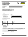
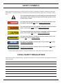
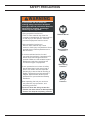
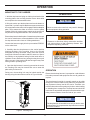
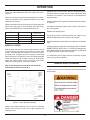
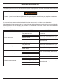
MOUNTED HYDRAULIC
DROP HAMMER
DH1500
DH3500
DH9000
Safety, Operation and Maintenance
USER’S MANUAL
© 2012 Stanley Black & Decker, Inc.
New Britain, CT 06053
U.S.A.
67737 5/2013 Ver. 8
TABLE OF CONTENTS
DECLARATION OF CONFORMITY.................................................................................................................................... 4
SAFETY SYMBOLS............................................................................................................................................................ 5
SAFETY PRECAUTIONS.................................................................................................................................................... 6
TOOL STICKERS & TAGS.................................................................................................................................................. 9
OPERATION...................................................................................................................................................................... 10
PRE-INSTALLATION INSTRUCTIONS.......................................................................................................................... 10
SKIDSTEER, BACKHOE OR EXCAVATOR SIZE.......................................................................................................... 10
TEST THE HYDRAULIC SYSTEM................................................................................................................................ 10
HYDRAULICS ............................................................................................................................................................... 10
TOOL INSTALLATION.................................................................................................................................................... 10
MOUNTING TO THE CARRIER.....................................................................................................................................11
OPERATION...................................................................................................................................................................11
ADJUSTING IMPACT..................................................................................................................................................... 12
MAINTENANCE................................................................................................................................................................ 12
DAILY INSPECTION ........................................................................................................................................................ 12
MONTHLY CHECK............................................................................................................................................................ 13
TRAVEL AND STORAGE.................................................................................................................................................. 13
TROUBLESHOOTING...................................................................................................................................................... 14
SPECIFICATIONS............................................................................................................................................................. 15
DH1500 PARTS ILLUSTRATION...................................................................................................................................... 16
DH1500 PARTS LIST........................................................................................................................................................ 17
DH3500 PARTS ILLUSTRATION...................................................................................................................................... 18
DH3500 PARTS LIST........................................................................................................................................................ 19
DH9000 PARTS ILLUSTRATION...................................................................................................................................... 20
DH9000 PARTS LIST........................................................................................................................................................ 21
IMPORTANT
To fill out a Product Warranty Recording form, and for information on your warranty,
visit Stanleyhydraulic.com and select the Warranty tab.
(NOTE: The warranty recording form must be submitted to validate the warranty).
SERVICING THE STANLEY HYDRAULIC DROP HAMMER. This manual contains safety, operation, and routine
maintenance instructions. Servicing of hydraulic tools, other than routine maintenance, must be
performed by an authorized and certified dealer. Please read the following warning.
SERIOUS INJURY OR DEATH COULD RESULT FROM THE
IMPROPER REPAIR OR SERVICE OF THIS TOOL.
REPAIRS AND / OR SERVICE TO THIS TOOL MUST ONLY BE
DONE BY AN AUTHORIZED AND CERTIFIED DEALER.
3
DECLARATION OF CONFORMITY
ÜBEREINSTIMMUNGS-ERKLARUNG
DECLARATION DE CONFORMITE CEE
DECLARACION DE CONFORMIDAD
DICHIARAZIONE DI CONFORMITA
Hydraulic Tools
______________________________________________________________________
I, the undersigned:
Ich, der Unterzeichnende:
Je soussigné:
El abajo firmante:
lo sottoscritto:
Weisbeck, Andy
Surname and First names/Familiennname und Vornamen/Nom et prénom/Nombre y apellido/Cognome e nome
hereby declare that the equipment specified hereunder:
bestätige hiermit, daß erklaren Produkt genannten Werk oder Gerät:
déclare que l’équipement visé ci-dessous:
Por la presente declaro que el equipo se especifica a continuación:
Dichiaro che le apparecchiature specificate di seguito:
1.
Category:
Kategorie:
Catégorie:
Categoria:
Categoria:
Drop Hammer, Breaker
2.
Make/Marke/Marque/Marca/Marca
Stanley
3.
Type/Typ/Type/Tipo/Tipo:
DH1500, DH1501, DH1502, DH3500, DH9000, DH9001
4.
Serial number of equipment:
Seriennummer des Geräts:
Numéro de série de l’équipement:
Numero de serie del equipo:
Matricola dell´attrezzatura:
All
Has been manufactured in conformity with
Wurde hergestellt in Übereinstimmung mit
Est fabriqué conformément
Ha sido fabricado de acuerdo con
E’ stata costruita in conformitá con
Directive/Standards
Richtlinie/Standards
Directives/Normes
Directriz/Los Normas
Direttiva/Norme
No.
Nr
Numéro
No
n.
Approved body
Prüfung durch
Organisme agréé
Aprobado
Collaudato
EN ISO
Machinery Directive
EN ISO
982:2008
2006/42/EC:2006
12100-1, 12100-2:2009
Self
Self
Self
5.
Special Provisions:
None
Spezielle Bestimmungen:
Dispositions particulières:
Provisiones especiales:
Disposizioni speciali:
6.
Representative in the Union: Patrick Vervier, Stanley Dubuis 17-19, rue Jules Berthonneau-BP 3406 41034 Blois Cedex, France.
Vertreter in der Union/Représentant dans l’union/Representante en la Union/Rappresentante presso l’Unione
Done at/Ort/Fait à/Dado en/Fatto a Stanley Hydraulic Tools, Milwaukie, Oregon USA
Signature/Unterschrift/Signature/Firma/Firma
Position/Position/Fonction/Cargo/Posizione
Engineering Manager
1/10/2011
4
Date/Datum/le/Fecha/Data
1-10-11
SAFETY SYMBOLS
Safety symbols and signal words, as shown below, are used to emphasize all operator, maintenance and repair
actions which, if not strictly followed, could result in a life-threatening situation, bodily injury or damage to equipment.
This is the safety alert symbol. It is used to alert you to potential personal
injury hazards. Obey all safety messages that follow this symbol to avoid
possible injury or death.
This safety alert and signal word indicate an imminently hazardous situation which, if not avoided, will result in death or serious injury.
This safety alert and signal word indicate a potentially hazardous situation
which, if not avoided, could result in death or serious injury.
This safety alert and signal word indicate a potentially hazardous situation
which, if not avoided, may result in minor or moderate injury.
CAUTION
This signal word indicates a potentially hazardous situation which, if not
avoided, may result in property damage.
NOTICE
This signal word indicates a situation which, if not avoided, will result in
damage to the equipment.
IMPORTANT
This signal word indicates a situation which, if not avoided, may result in
damage to the equipment.
Always observe safety symbols. They are included for your safety and for the protection of the tool.
LOCAL SAFETY REGULATIONS
Enter any local safety regulations here. Keep these instructions in an area accessible to the operator and maintenance personnel.
5
SAFETY PRECAUTIONS
WARNING
Do not operate the tool unless the
following safety instructions have been
thoroughly read and understood! Read this
manual before installing, operating or
maintaining this equipment.
A flying projectile from the tool,
Rock or other material may enter the
operator's compartment and cause serious
or fatal injury to the operator. Personal
protection equipment must be used.
A flying projectile from the tool
Rock or other material may cause
serious or fatal injury to bystanders. Never
operate the tool when bystanders are in
the work area.
On some machines/carriers, the tool
can enter the operator's compartment if it
breaks loose and swings toward the
operator. Make sure that suitable impact
shields are used when operating the
Tool with this type of equipment.
Do not operate the tool unless all safety
decals described in this manual are in
place. The decals must be inspected
periodically to ensure that all wording is
legible. The decals must be replaced if
illegible. Replacement decals can be
obtained from your authorized Stanley
Distributor.
When operating the tool you must use
ear protection, eye protection, and
breathing protection.
Exposure to silica dust during construction
activities can cause serious or fatal respiratory
disease. Use adequate respiratory protection.
6
Read the Manual
Wear Breathing
Protection
Wear Hearing
Protection
Wear Eye
Protection
SAFETY PRECAUTIONS
Tool operators and maintenance personnel must always comply with the safety
precautions given in this manual and on the stickers and tags attached to the tool and
hose.
These safety precautions are given for your safety. Review them carefully before operating
the tool and before performing general maintenance or repairs.
Supervising personnel should develop additional precautions relating to the specific work
area and local safety regulations. If so, place the added precautions in the space provided
on page 5 in this manual.
The mounted hydraulic drop hammers will provide safe and dependable service if
operated in accordance with the instructions given in this manual. Read and understand this
manual and any stickers and tags attached to the tool and hoses before operation. Failure
to do so could result in personal injury or equipment damage.
Check the rules and regulations at your location. The rules might include an employer's
work safety program. Regulations may identify hazards such as working around utility supply lines or hazardous slopes.
BE THOROUGHLY TRAINED BEFORE OPERATING THE UNIT ALONE
• Operator training must start in an area without bystanders and use all the controls until he/she can control the machine
fully under the conditions of the work area.
• When learning to operate a machine, do so at a slow pace.
KNOW THE WORK CONDITIONS
• The operator must know any prohibited uses or work areas for the machine. For example, excessive slopes and poor or
dangerous terrain conditions must be avoided.
OBEY SAFETY RULES
• Operate the tool in accordance with all laws and regulations which affect you, your equipment and the work-site.
• Do not operate the tool until you have read this manual and thoroughly understand all safety, operation and
maintenance instructions.
• The operator must be familiar with all prohibited work areas such as excessive slopes and dangerous terrain
conditions.
• Do not operate the tool until you have read the carrier equipment manual and thoroughly understand all safety,
operation and maintenance instructions. The word “carrier”, as used in this manual, means a skidsteer loader, backhoe or
excavator used to operate the tool.
• Ensure that all maintenance procedures recommended in this manual are completed before using the equipment.
•
Warning: Use of this tool on certain materials during demolition could generate dust potentially containing a variety of
hazardous substances such as asbestos, silica or lead. Inhalation of dust containing these or other hazardous substances
could result in serious injury, cancer or death. Protect yourself and those around you. Research and understand the ma
terials you are cutting. Follow correct safety procedures and comply with all applicable national, state or provisional health
and safety regulations relating to them, including, if appropriate arranging for the safe disposal of the materials by a quali
fied person.
7
SAFETY PRECAUTIONS
• The operator must not operate the tool or carrier if any people are within the area where they may be injured by flying
debris or movement of the equipment.
• Know the limits of your equipment.
• Establish a training program for all operators to ensure safe operation.
• Do not operate the tool unless thoroughly trained or under the supervision of an instructor.
• Become familiar with the carrier controls before operating the carrier and the tool.
• When operating the tool you must use ear protection, eye protection, and breathing protection.
• While learning to operate the tool and carrier, do so at a slow pace. If necessary, set the carrier mode selector to the
slow position.
• Make sure all controls (levers and pedals) are in the NEUTRAL position before starting the carrier.
• While operating the tool and carrier, keep hands and feet on the controls at all times.
• Before leaving the carrier, always lower the boom and insure the carrier is stable. Never leave the machine with the
engine running. ALWAYS ENGAGE THE PARKING BRAKE.
• Stop the engine before attempting to make any repairs, adjustments or servicing to either the carrier or the tool.
• Do not operate the tool at oil temperatures above 190°F/88°C. Operation at higher temperatures can damage the internal
components of the equipment and will result in reduced performance.
• Do not operate a damaged, leaking, improperly adjusted, or incompletely assembled tool.
• Do not modify the tool in any manner.
• To avoid personal injury or equipment damage, all tool repair, maintenance and service must only be performed by
authorized and properly trained personnel.
• If you do not understand how to safely operate your tool, contact an authorized Stanley Dealer for assistance.
• Keep this manual with the tool.
• Do not operate this equipment if you are taking medication which may affect your mental judgement or physical
performance.
• Do not operate this equipment if you are under the influence of drugs or alcohol.
• Replace all faulty or leaking hydraulic hoses before further operation.
• After operation, hydraulic components may be hot enough to burn skin.
8
TOOL STICKERS & TAGS
E ART PROOF Job # 53565
as is.
y
4-25-07
Make indicated changes and proceed.
Stanley
P.O. 750376
GILLESPIE ART PROOF Job #54077 5-17-07 Stanley (15820)
P.O. 751392
Approved By_______________________________ Date_____________
Proof OK as is.
Make indicated changes and proceed.
Make changes and send another proof.
Fax: 503•682•2542
Approved by
Date
Make changes and send another proof.
Date
PLEASE CHECK CAREFULLY. Gillespie Graphics, Inc. does not accept responsibility for errors after final approval.
ME
Refer to the Parts Illustration page in this manual for proper placement of stickers.
GILLESPIE ART BLUE PRINT
Quantity: 300
Nacco MTLS Handling Group (91040)
PN: 1581055 Hoist Tilt
Blue Print Created On: 04-May-07
Blue Print Created By: ME
Fax: 503•682•2542
R/C .125”
6.5”
Fax: 503•682•2542
PN: 67791
HECK CAREFULLY. Gillespie Graphics, Inc. does not accept responsibility for errors after final approval.
6”
Lamination:
Printer / Press:
Fonts Used:
Adhesive:
Application Tape:
Material: AD-1487
Cut: Steel Rule Die Cut
Die Location:
R/C:
Score:
6”
Approved By_______________________________ Date_____________
PMS 144 Orange
123 Yellow
®
Ensure travel lock is correctly installed.
KEEP CLEAR OF TOP OF
DROP HAMMER
DH 3500
Fax: 503•682•2542
Black
GILLESPIE ART BLUE PRINT
Impact Hazard
Contact with moving weight could
result in serious injury or death.
Lamination:
Printer / Press:
Material: AD-1487
Cut: Steel Rule Die Cut
Die Location:
R/C:
Score:
Nacco MTLS Handling Group (91040)
PN: 1581055 Hoist Tilt
Blue Print Created On: 04-May-07
Blue Print Created By: ME
4”
Fonts Used:
Sliding / crushing
hazard from weight.
Adhesive:
Application Tape:
The sliding weight can cause serious
injury or death.
Clear
6785
67791
Cut Line
(does not print)
Black
Scaled @ 30%
Cut Line
Approved By_______________________________
Date_____________
(does not print)
67791
Drop Hammer Sticker
Fax: 503•682•2542
GILLESPIE
ART PROOF Job #54077 5-16-07 Stanley (15820)
Proof OK as is.
Make indicated changes and proceed.
Approved by
Date
PLEASE CHECK
Gillespie Graphics, Inc. does not accept responsibility for errors after final approval.
GILLESPIE
ARTCAREFULLY.
BLUE PRINT
Lamination:
Material: AD-1487
ME
Nacco MTLS Handling Group (91040)
Quantity:
Blue Print Created On: 04-May-07
300
Blue Print Created By: ME
R/C .125”
Printer503•682•2542
/ Press:
Fax:
Fonts Used:
Cut: Steel Rule Die Cut
Die Location:
R/C:
Score:
PN: 1581055
PN: 67859 Travel
lockHoist Tilt
29”
P.O. 751392
Make changes and send another proof.
Adhesive:
Application Tape:
6”
47351
Composite Warning
Sticker
GILLESPIE ART PROOF Job #54077 5-17-07 Stanley (15820)
Fax: 503•682•2542
Approved
by
Quantity:
300
GILLESPIE ART BLUE PRINT
R/C .125”
Nacco MTLS Handling Group (91040)
PN: 1581055 Hoist Tilt
Blue Print Created On: 04-May-07
Blue Print Created By: ME
Clear
Cut Line
(does not print)
67859
Travel Lock Sticker
Proof OK as is.
Approved by
P.O. 751392
Make changes and send another proof.
Fax: 503•682•2542
PN: 67860 Toppling Hazard
Quantity: 300
R/C .125”
Ensure travel lock is correctly installed.
DANGER
The sliding weight can cause serious
injury or death.
67768
DH1500 Model Number Sticker
67735
DH3500 Model Number Sticker
Lay down on hard, flat level
ground only.
Do not store standing upright.
Death or serious injury
will result.
68581
DH3500 CE Spec Plate
70982
DH9000 CE Spec Plate
Clear
67861
Stability Sticker
Cut Line
(does not print)
RED
GILLESPIE ART PROOF Job #54077 5-17-07 Stanley (15820)
Proof OK as is.
Make indicated changes and proceed.
Approved by
Black
P.O. 751392
Make changes and send another proof.
Date
PLEASE CHECK CAREFULLY. Gillespie Graphics, Inc. does not accept responsibility for errors after final approval.
ME
4”
Fax: 503•682•2542
PN: 67862 Equip Damage Hazard
Quantity: 300
Clear
67860
67860
Toppling & Crush Sticker
Cut Line
(does not print)
67780
DH9000 Model Number Sticker
Specification Plate
68641
DH1500 CE Spec Plate
Black
4”
67861
6”
Sliding / crushing
hazard from weight.
TOPPLING & CRUSH
HAZARD!
PMS 123 Yellow
Skids must be firmly on material being
broken while machine is in operation.
Failure to comply may result in
equipment damage.
Date
PLEASE CHECK CAREFULLY. Gillespie Graphics, Inc. does not accept responsibility for errors after final approval.
ME
Lamination:
Printer / Press:
Fonts Used:
Adhesive:
Application Tape:
EQUIPMENT DAMAGE AND
STABILITY HAZARD!
67859
Cut Line
Make indicated
and proceed.
(doeschanges
not print)
6”
Material: AD-1487
Cut: Steel Rule Die Cut
Die Location:
R/C:
Score:
CAUTION
The sliding weight can cause serious
injury or death.
GILLESPIE ART PROOF Job #54077 5-16-07 Stanley (15820)
Fax: 503•682•2542
PN: 67861 Stability Hazard
4”
Sliding / crushing hazard from weight.
Date
PLEASE CHECK CAREFULLY. Gillespie Graphics, Inc. does not accept responsibility for errors after final approval.
ME
Black
Ensure travel lock is correctly installed.
P.O. 751392
Proof OK as
is.
Make indicated changes and proceed.
Make changes and send another proof.
Approved
By_______________________________
Date_____________
PMS 144 Orange
R/C .125”
6”
CAUTION
PMS 123 Yellow
EQUIPMENT DAMAGE HAZARD!
Repeated blows in material 6 inches
or less can result in Dry-firing.
Failure to comply may result in
machine damage.
Keep breaker moving.
Black
4”
67862
67862
Equipment Damage Sticker
Cut Line
(does not print)
52539 (DH1500)
Sound Power Level Sticker
60917 (DH3500)
Sound Power Level Sticker
52539 (DH9000)
Sound Power Level Sticker
9
Clear
OPERATION
PRE-INSTALLATION INSTRUCTIONS
SKIDSTEER, BACKHOE OR EXCAVATOR SIZE
Check the Specifications section of this manual to
determine correct carrier size, hydraulic flow and pressure
requirements.
If hydraulic pressure, hydraulic back-pressure,
hydraulic flow or excavator weight class are exceeded, the
drop hammer warranty is void.
Before connecting the drop hammer to the carrier hydraulic
system; it is important to determine which are the pressure and
tank lines of the carrier and connect the hoses appropriately.
The pressure and tank lines are marked where they enter the
valve block. If the hydraulics are connected incorrectly, the
motor will rotate in the wrong direction. This will not damage
the machine but it will not lift.
TOOL INSTALLATION
WARNING
Do not lift or transport the drop hammer without the
travel lock installed.
Do not use bare hands to check or search for hydraulic
leaks around hoses and fittings. Pinhole leaks can
penetrate the skin. To inspect for leaks, depressurize
the system, clean around suspected area, repressurize
the system and visually check for leaks.
The hammer can move freely in the housing if the
travel lock is not installed which can result in serious
injury or death.
Ensure travel lock is installed.
TEST THE HYDRAULIC SYSTEM
1. Have your Stanley dealer test the carrier hydraulic
system to make sure the system is operating at the
manufacturers specified capacity and pressure ratings.
2. Be sure the fluid in the hydraulic system is clean.
The drop hammer may be lifted with a forklift through the
mounting bracket or by feeding chains through the points
shown in Figure 1 below. Always lift the drop hammer with
machinery and lifting equipment that is rated to carry the
weight of the machine.
3. Check the hydraulic filter. Replace the filter if dirty or
deteriorated.
4
Have your Stanley dealer test the circuit to which the
breaker will be connected to make sure that the circuit is
supplying the specified flow and pressure rating for the
breaker. See the Specifications section of this manual.
Traveling
Lock
Center of
Gravity
HYDRAULICS
Some carriers may have flows above or below flow and
pressure ranges required. Refer to Flow and Pressure
Specifications on page 17 of this manual. If the flow is lower
the drop hammer will simply cycle at a slower rate. If the flow
rate is higher the control valve on the drop hammer will limit
the flow to prevent the chain over-speeding and catching the
weight as it drops.
Figure 1. Lift Points
10
Mounting Bracket
OPERATION
MOUNTING TO THE CARRIER
OPERATION
1. With the drop hammer laying on a flat level surface bolt the
mounting plate to the mounting bracket. Ensure these bolts
are torqued to the recommended value.
NOTICE
2. Bring the carrier up to the drop hammer from the bottom or
impact end. If you have a quick attachment systems maneuver
the mount plate on the carrier until it engages with the adaption
plate. Then actuate the slides or levers to lock the plates
together. With a pin mount system; maneuver the carrier until
the pinholes are aligned and slide in the connection pins.
Failure to remove the travel lock may result in damage
to the equipment during operation.
Ensure the pins are bolted in place. Grease these pivots as per
the carrier manufactures recommendations. Never operate
the drop hammer with a loose or ill-fitting attachment.
Exposure to silica dust during construction activities
can cause serious or fatal respiratory disease. Use
adequate respiratory protection.
Connect the hoses to supply oil to the port marked "PRESS"
on the valve block.
3. Carefully raise the drop hammer to the vertical position
keeping the base of the machine close to the ground
throughout the lifting movement. Slowly move the Cyclone
through the full extent of rotation and lift to ensure no part of
the machine or any hydraulic hosing foul the carrier arms or
cylinders. Ensure hoses are long enough so they do not pull
tight in any part of the rotation and short enough to stay clear
of the ground or operating area.
4. Once the drop hammer is securely mounted to the carrier
the Traveling Lock may be removed. Be sure to store this
plate safely for future use.
During use, the traveling lock may be bolted outside the
housing using the same hole as shown in Figure 2 below.
OPERATION
Ensure that the drop hammer is operated at a safe distance
from other personnel and equipment. Be sure all guards are
in place.
The drop hammer's weight is normally rested on the skids
during use. However when moving about the drop hammer
may represent a heavy load for the carrier. Therefore care
must be taken when moving about a job-site or when loading
or unloading from a transporter. The drop hammer should be
carried as low as possible and special care taken when negotiating uneven surfaces. Know the limits of your carrier.
Traveling Lock
NOTICE
The drop hammer is intended for use only on level or near
level surfaces. Do not operate the drop hammer on uneven
or unlevel surfaces.
Figure 2. Traveling Lock
11
OPERATION
GENERAL TECHNIQUE FOR BREAKING SLAB
1. Tip the drop hammer to a horizontal position.
Rest the drop hammer in a vertical position on the concrete
to be broken. The skids should be just resting on the concrete
with some of the weight taken by the carrier. If a crack appears
in the top surface of the concrete you can be sure it is broken
all the way through.
2. Gradually move the drop hammer past horizontal until the
weight slides forward. This can be done in a controlled manner
by shaking the weight out using the curl lever.
Actuate the hydraulics and the drop hammer will start to cycle.
As the concrete cracks or breaks move the carrier. It is best
to move while the hammer is raised and pause momentarily
as the hammer strikes.
Generally all that is required is to hit the concrete until it cracks
and then move 6-12 inches /150-300 mm. Sitting in one place
will pulverize the concrete and eventually the hammer will hit
the column buffers. This is felt as a hard jarring action through
the machine.
With skid steers movement can be in any direction but generally moving in a reverse direction provides the best control.
On excavators setting the machine down and moving in arc
with the slew drive is usually the quickest method.
3. Allow the Hammer to slide out until it hits against the Safety
Pin.
4. Return the drop hammer to horizontal and rest it on the
ground and Shut the carrier off.
5. On the under-side of the Hammer remove the Bolt and Peg
Locking Plate that hold the Hammer Peg.
6. Remove the Hammer Peg and replace it in the next hole.
Tighten to 180 ft/lbs/240 Nm for the DH3500 and DH9000,
for the DH1500 tighten to 140 ft lbs/190 Nm with the Bolt and
Peg Locking Plate. See Figure 3 below.
Hammer Peg
Hex Head Setscrew
Peg Locking Plate
It is important to keep the drop hammer as vertical as possible
during operation as this provides the greatest impact.
When breaking thinner concrete, the drop hammer may hit
too hard and punch completely through. In this instance the
hammer sticking into the concrete and stopping the carrier
traveling can slow production. If this occurs adjust the impact
of the drop hammer as described below.
Hammer Safety Pin
Hammer
Figure 3. Hammer Adjustment
7. Restart the carrier and SLOWLY raise the drop hammer
until the Hammer slides down the column.
MAINTENANCE
It is recommended that only genuine Stanley parts are used.
Genuine Stanley drop hammer parts are all checked for
allowable tolerances.
ADJUSTING IMPACT
Although the drop hammer is a simple machine, it is subject
to severe stresses and shocks during normal operation. A
five-minute daily check will ensure that your drop hammer
remains in good condition and will prevent unscheduled
down time.
DAILY INSPECTION
Check that all the mount plate bolts that connect the drop
hammer to the carrier are tight and torqued to the recommended value.
Check that the motor flange bolts are tight and secure.
12
OPERATION
Standing clear of the machine, start the drop hammer and
SLOWLY rotate the chain until the chain Connecting Plate
Assembly is accessible. Turn the carrier off and disconnect
hydraulic hoses.
Check the chain adjustment bolts and secure the nuts if
required.
Check the Housing Cover plate bolts and tighten if needed.
Check the hydraulic hoses, fittings and valves for any leaks
and repair as required.
Check this assembly for signs of excessive wear, and replace
as required.
With the machine turned off, oil the chain over the top sprocket
with a heavy duty gear oil such as Mobil Gear 600 Series.
Refer to the table below for recommended chain oil.
Ambient Temperature
Lubricant Rating (SAE)
Viscosity Grade
(Hydraulic Fluid)
23° - 41°F / -5° - +5°C
20
46 - 68
41° - 104°F / 5° - 40°C
30
100
104° - 122°F / 40° - 50°C
40
150 - 220
122° - 140°F / 50° - 60°C
50
320
Lubricate this assembly and the chain. Refer to the table on
the previous page.
Replace the Housing Cover.
Tip the drop hammer forward and slide the weight out as
described Adjusting Impact section of this manual.
Inspect the Hammer Connecting Pin and replace if excessively
worn.
MONTHLY CHECK
Liberally grease the Hammer Connecting Pin USE A LITHIUM
BASED GREASE WITH NGLI 1 or 2 RATING (Mobilgrease
HP or Shell Alvania EP) and replace the hammer as described
in Adjusting Impact section of this manual.
With the drop hammer in a vertical position and the carrier
turned off remove the Housing Cover plate. Check the chain
tension. The chain should move about 1/2 inch/10-15 mm at
its center point. To adjust the chain, loosen the Tensioning
Bolt lock nuts (Item 32 DH1500 or Item 30 DH3500) and the
Clamp Nut (Items 41-42 DH1500 or Items 34-35 DH3500).
Adjust the Tension Bolts evenly (so that the lower shaft/
sprocket are kept parallel). See Figure 4 below.
It is worthwhile at this stage to dress the hammer tip and
remove any excessive burring.
TRAVEL AND STORAGE
Note: In the first month of operation this should be
done weekly until the chain beds in.
1. Ensure the travel lock is installed before transporting the
drop hammer.
Sprocket
Spacer
Adjuster
Bracket
Nut
Lower
Sprocket
Shaft
Half Nut
Bearing
Washer
Nut
Bearing
Nut
Washer
Hex Head Setscrew
(Long)
Washer
Hex Head Setscrew
(Short)
Figure 4. Lower Sprocket Assembly
Remove the rubber inspection cover at the top of the drop
hammer and check the motor nut is tight. Replace the
inspection cover.
13
TROUBLESHOOTING
This section describes how to find and resolve problems users may experience. If a situation occurs that is not covered, call
your Stanley Customer Service representative for assistance.
WARNING
Inspecting the tool or installing parts with the hydraulic hoses connected can result in severe personal injury or equipment
damage. To prevent accidental startup, disconnect the hydraulic power before beginning any inspection or installation
task.
If symptoms of poor performance develop, the following chart can be used as a guide to correct the problem.
When diagnosing faults in operation of the tool, always check that the hydraulic power source is supplying the correct hydraulic
flow and pressure to the tool as listed in the table below. Use a flowmeter known to be accurate. Check the flow with the
hydraulic oil temperature at least 80° F/27° C.
PROBLEM
Hammer will not fire.
CAUSE
Reverse the flow.
Low hydraulic oil level.
Fill reservoir.
No flow to breaker.
Have hydraulic circuit tested by
authorized dealer/distributor per
approved procedure.
Main relief set low.
Internal damage.
Have unit serviced by an authorized
dealer/distributor.
Damaged quick couplers.
Replace.
Low hydraulic flow
Have hydraulic circuit tested by an
authorized dealer/distributor per
approved procedure.
Internal leakage.
Have unit serviced by an authorized
dealer/distributor.
Hammer runs slowly.
Damaged switch or connection.
Hammer runs erratically.
SOLUTION
Hydraulic flow is in wrong direction.
Relief set too low.
Internal damage.
Have carrier serviced by an authorized
dealer/distributor.
Hammer binding.
Clean hammer in housing.
Chain tension too tight
Have unit serviced.
Main relief set low.
Hydraulic system overheats.
Insufficient cooling capability in hydraulic
Have unit serviced by an authorized
circuit.
dealer/distributor.
Line/hose size too small.
Excessive back-pressure.
14
SPECIFICATIONS
DIMENSIONS AND WEIGHTS
Weight w/o Mounting Bracket
DH1500.....................................................................................................................................................700 lbs / 317.5 kg
DH3500......................................................................................................................................................1570 lbs / 712 kg
DH9000....................................................................................................................................................3100 lbs / 1406 kg
Height
DH1500.................................................................................................................................................... 63.75 in. / 162 cm
DH3500...................................................................................................................................................... 65.5 in. / 166 cm
DH9000.................................................................................................................................................. 74.375 in. / 189 cm
Hydraulic Pressure Range
DH1500....................................................................................................................................2300-3000 psi / 159-207 bar
DH3500....................................................................................................................................2350-3000 psi / 162-207 bar
DH9000....................................................................................................................................2400-3000 psi / 166-207 bar
Minimum Flow Range
DH1500.........................................................................................................................................8.7-20.6 gpm / 33-78 lpm
DH3500.......................................................................................................................................10.6-20.6 gpm / 40-78 lpm
DH9000........................................................................................................................................ 20.6-31 gpm / 78-117 lpm
Recommended Hose............................................................................................................................... 5/8" Parker 451TC
NOTE: Weights, dimensions and operating specifications listed on this sheet are subject to change without notice. Where specifications are critical to your application, please consult the dealer.
15
MODEL & SERIAL
NUMBER LOCATION
DH1500 PARTS ILLUSTRATION
16
DH1500 PARTS LIST
Item
SHT No.
Qty
1
04353
8
2
04585
3
06638
4
07860
Description
Item
SHT No.
Qty
Description
NYLOCK NUT
41
67801
1
HEX NUT
16
WASHER
42
67802
1
HEX JAM NUT
4
HSHCS
43
67803
1
WASHER
8
HSHCS
44
67804
1
HHCS
67820
1
HHCS
7
20871
2
HHCS
45
8
20908
1
HHCS
46
67852
1
LEFT SIDE LIFT LUG
9
44956
4
NYLOCK NUT
47
67859
1
DECAL, TRAVEL LOCK
48
67860
2
DECAL, TOPPLING HAZARD
49
67861
1
DECAL, STABILITY HAZARD
50
67869
2
HOSE
10
47351
1
DECAL, COMPOSITE
WARNING
11
52539
1
SOUND POWER LEVEL
12
67709
1
INSPECTION COVER
15
69803
1
BRACKET WELDMENT
16
67740
1
HOUSING
17
67747
1
HAMMER MACHINING
18
67748
1
HAMMER PEG
19
67749
1
PEG LOCKING PLATE
20
67750
1
HAMMER SAFETY PIN
21
67751
1
RIGHT SIDE LIFT LUG
22
67752
1
CENTER LIFT LUG
23
67753
1
MOTOR SPROCKET
24
67754
1
CHAIN
25
67755
1
SHAFT CYCLONE
26
67756
1
SPROCKET SPACER
27
67757
1
ADJUSTER BRACKET
29
67767
2
POLY-BUSH
30
67768
3
DECAL, DH1500
31
69788
1
VALVE ASSEMBLY
32
67788
2
HEX NUT END
33
67789
6
WASHER
34
67790
2
HHCS
35
67791
2
DECAL, KEEP CLEAR OF
HAMMER
36
67792
1
HHCS
37
67796
2
LIFT LUG SPACER
38
67797
1
HHCS
39
67798
1
FLEX LOCK NUT
40
67799
2
HSHCS
51
17
NO ITEM
52
68023
1
LOWER SPROCKET ASSY
53
68340
2
FLEX LOCK NUT
54
68542
1
HYDRAULIC MOTOR
55
68578
4
HHCS
56
68641
1
CE SPECIFICATION PLATE
59
371050
3
WASHER
60
371500
1
NYLOCK NUT
61
371507
2
NYLOCK NUT
62
67746
1
HAMMER STOP
63
67742
1
TRAVELING LOCK
64
67741
1
HOUSING COVER
65
70788
1
NYLOCK NUT
66
00354
2
O-RING
MODEL & SERIAL
NUMBER LOCATION
DH3500 PARTS ILLUSTRATION
18
DH3500 PARTS LIST
Item
SHT No.
Qty
1
06638
4
4
20871
5
23630
6
44956
Description
Item
SHT No.
Qty
Description
HSHCS
41
67812
2
SCREW FOR CHAIN
8
HHCS
42
67813
2
CRIMP LOCK NUT
2
HHCS
43
67820
1
HHCS
4
NYLOCK NUT
44
67853
1
LEFT SIDE LIFT LUG
67859
1
DECAL, TRAVEL LOCK
7
47351
1
DECAL, COMPOSITE
WARNING
45
8
60917
1
SOUND POWER LEVEL
46
67860
2
DECAL, TOPPLING HAZARD
9
67703
1
HOUSING
47
67861
1
DECAL, STABILITY HAZARD
10
67709
1
INSPECTION COVER
48
67869
2
HOSE
11
67710
1
HAMMER MACHINING
12
67711
1
HAMMER PEG
13
67712
1
PEG LOCKING PLATE
14
67713
1
HAMMER SAFETY PIN
15
67714
1
RIGHT SIDE LIFT LUG
16
67716
1
CENTER LIFT LUG
17
67717
1
MOTOR SPROCKET
18
67718
1
CHAIN
19
67719
1
SHAFT, CYCLONE
20
67720
1
SPROCKET SPACER
21
67721
1
ADJUSTER BRACKET
25
67734
2
POLY-BUSH
26
67735
3
DECAL, DH3500
27
67736
1
BRACKET WELDMENT
28
69789
1
VALVE ASSEMBLY
29
67787
1
HHCS
30
67788
2
HEX NUT
31
67789
5
WASHER
32
67791
2
DECAL, KEEP CLEAR OF
HAMMER
33
67795
1
NYLOCK NUT, HOLDS
SPROCKET TO MOTOR
34
67801
1
HEX NUT
35
67802
1
HEX JAM NUT
36
67803
1
WASHER
37
67808
1
HHCS
38
67809
2
LIFT LUG SPACER
39
67810
1
SCREW FOR SPACER
40
67811
1
NUT FOR SPACER
49
19
NO ITEM
50
68024
1
LOWER SPROCKET ASSY
51
68543
1
HYDRAULIC MOTOR
52
68578
4
HHCS
53
68581
1
CE SPECIFICATION PLATE
56
370352
1
HHCS
57
371050
10
WASHER
58
371052
4
WASHER
59
371500
8
NYLOCK NUT
60
371501
2
NYLOCK NUT
61
371507
1
NYLOCK NUT
62
67708
1
HAMMER STOP
63
67705
1
TRAVELING LOCK
64
67704
1
HOUSING COVER
65
02504
2
CAPSCREW
66
00354
2
O-RING
MODEL & SERIAL
NUMBER LOCATION
DH9000 PARTS ILLUSTRATION
20
DH9000 PARTS LIST
Item
SHT No.
Qty
1
00719
2
2
04539
2
3
04786
4
6
Description
Item
SHT No.
Qty
NYLOCK NUT
41
68331
2
FLANGE BEARING PILOTED
WASHER
42
68332
2
KEY
1
WASHER
43
68366
1
HAMMER PEG
06638
4
HSHCS
44
68503
2
FLANGE BEARING
18600
10
NYLOCK NUT
45
68504
2
SHAFT ADJUSTER BRACKET
8
20871
12
HHCS
46
68506
2
HHCS
9
47351
1
DECAL, COMPOSITE
WARNING
47
68519
4
SETSCREW
10
67712
1
PEG LOCKING PLATE
48
68520
1
HHCS
11
67713
1
HAMMER SAFETY PIN
49
68521
2
SHOULDER SCREW
12
67714
1
RIGHT SIDE LIFT LUG
50
68578
6
HHCS
13
67716
3
CENTER LIFT LUG
51
69654
5
HHCS
16
67738
1
CHAIN WEAR SHEET
52
70982
1
CE SPEC PLATE
17
67764
1
HAMMER MACHINING
54
370252
2
HHCS
18
67771
1
HOUSING
55
370253
4
HHCS
19
67775
1
LOWER SHAFT
20
69790
1
MANIFOLD BLOCK
22
67779
2
POLY-BUSH
23
67780
3
DECAL, DH9000
24
67781
1
BRACKET WELDMENT
25
67790
4
HHCS
26
67791
2
DECAL, KEEP CLEAR OF
HAMMER
27
67805
4
HHCS
28
67808
1
HHCS
29
67809
4
LIFT LUG SPACER
30
67853
1
LEFT SIDE LIFT LUG
31
67859
1
DECAL, TRAVEL LOCK
32
67860
2
DECAL, TOPPLING HAZARD
33
67861
1
DECAL, STABILITY HAZARD
34
67862
1
DECAL, EQUIP DAMAGE
35
67869
1
HOSE
36
67869
1
HOSE
37
67896
1
CHAIN
38
68213
1
DRIVE SHAFT
39
68277
2
SPROCKET
40
68280
1
HYDRAULIC MOTOR
21
Description
56
371050
16
WASHER
57
371500
16
NYLOCK NUT
58
371506
4
HEX NUT
59
67628
6
NYLOCK NUT
60
372037
1
SERIAL NUMBER PLATE
61
372155
2
DRIVE PIN
62
67773
1
TRAVELING LOCK
63
68206
1
HOUSING COVER
64
00354
2
O-RING
Stanley Hydraulic Tools
3810 SE Naef Road
Milwaukie, Oregon 97267
503-659-5660 / Fax 503-652-1780
www.stanleyhydraulic.com
To fill out a Product Warranty Recording form, and for information on your warranty,
visit Stanleyhydraulic.com and select the Warranty tab.
(NOTE: The warranty recording form must be submitted to validate the warranty).