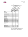
1
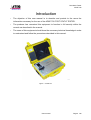
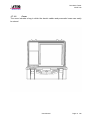
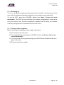
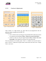
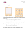
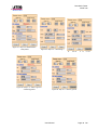
http://www.avionteq.com/ATEQ-Omicron-ADSE-735-Non-RVSM-Pitot-Static-Testers.aspx www.avionteq.com Pitot Static Tester ADSE 735 ADSE 735 Pitot Static Tester User Manual Author F. PLATEL Approved by E.DUTITRE User manual Page 1 /66 Pitot Static Tester ADSE 735 Revisions Date Edition Reference Creation November 2005 01 D2-0105-CL-A Update trouble shooting guide August 2006 02 D2-0105-CL-B Change pics + starting procedure October 2006 03 D2-0105-CL-C Change pics March 2007 04 D2-0105-CL-D Update Option November 2007 05 D2-0105-CL-E Update screen March 2008 06 D2-0105-CL-F User manual Page 2 /66 Pitot Static Tester ADSE 735 Table of contents 1. PRESENTATION .......................................................................................................6 1.1 General..............................................................................................................................6 1.2 Applications ......................................................................................................................7 1.3 Characteristics ..................................................................................................................8 1.4 Equipment Reference .......................................................................................................8 1.5 Pressure sensor ...............................................................................................................9 1.6 Main units, measurement range and accuracy of the generator between 0°C and +40°C .........................................................................................................................................9 1.6.1 1.6.2 1.6.3 1.6.4 Static pressure - Ps......................................................................................................................9 Total and differential pressure - Pt - ∆P .....................................................................................10 Ps dynamic variation ..................................................................................................................11 Pt dynamic variation...................................................................................................................11 1.7 Rates of intrinsic leak .....................................................................................................11 1.8 Technical description .....................................................................................................12 1.8.1 Main box.....................................................................................................................................13 1.8.1.1 Front panel ..........................................................................................................................13 1.8.1.2 Cover ...................................................................................................................................14 ..........................................................................................................................................................14 1.8.1.3 Electro-pneumatic unit.........................................................................................................15 1.8.1.3.1 Sensor...........................................................................................................................15 1.8.1.3.2 Servo-valve ...................................................................................................................15 1.8.1.3.3 Power supply ................................................................................................................16 1.8.1.3.4 Computer ......................................................................................................................16 1.8.1.3.5 Security ........................................................................................................................16 1.8.2 Software ..................................................................................................................................17 1.8.2.1 Computer .............................................................................................................................17 1.8.2.1.1 Management of the serial link.......................................................................................17 1.8.2.1.2 Sensor Management ....................................................................................................17 1.8.2.1.3 Management of the servo-controls ...............................................................................17 1.8.2.2 Management of securities ...................................................................................................18 1.8.3 User Interface.............................................................................................................................19 2. Using the ADSE 735 ...............................................................................................21 2.1 Preparing for use ............................................................................................................21 2.1.1 2.1.2 2.1.3 2.1.4 2.1.5 Installation ..................................................................................................................................21 Electrical connection ..................................................................................................................21 Pneumatic connection................................................................................................................22 Powering up ...............................................................................................................................27 Turning off the equipment ..........................................................................................................27 2.2 Using the interface..........................................................................................................28 2.2.1 Starting the software ..................................................................................................................28 2.2.2 .Flight range limits ......................................................................................................................29 2.2.2.1 Select a flight domain ..........................................................................................................30 2.2.2.2 Creation of a flight domain...................................................................................................31 2.2.2.3 Editing a flight domain .........................................................................................................32 2.2.3 Controller / Generator ................................................................................................................33 2.2.3.1 Pneumatic link .....................................................................................................................34 2.2.3.2 Ps generation ......................................................................................................................35 User manual Page 3 /66 Pitot Static Tester ADSE 735 2.2.3.2.1 Unit change...................................................................................................................37 2.2.3.2.2 Generation ....................................................................................................................37 2.2.3.2.3 . Execution of the flight instruction ................................................................................38 2.2.3.2.4 Leak Test ......................................................................................................................39 2.2.3.2.5 Return to the ground .....................................................................................................40 2.2.3.2.6 Exiting the Controller/Generator mode .........................................................................40 2.2.3.2.7 Visualizing the flight domain .........................................................................................41 2.2.3.3 Pt Generation ......................................................................................................................42 2.2.4 Automatic program mode...........................................................................................................43 2.2.4.1 Writing a new program ........................................................................................................44 2.2.4.2 Visualizing and editing a program .......................................................................................47 2.2.4.3 Executing a program with the user interface.......................................................................48 2.2.5 Calibration mode ........................................................................................................................52 2.2.5.1 Calibrating the sensor..........................................................................................................52 2.2.5.2 Use of the interface .............................................................................................................53 2.2.6 General Information ...................................................................................................................55 2.2.6.1 Changing a password..........................................................................................................56 2.2.7 Exiting the software....................................................................................................................57 3. APPENDIX ...............................................................................................................58 3.1 Error messages ...............................................................................................................58 3.2 Trouble shooting.............................................................................................................60 3.2.1 Problem with the Electro-Pneumatic Unit ..................................................................................60 3.2.2 Problem with the Remote Control Unit.......................................................................................61 3.2.2.1 Message « Battery Low »and total discharge of the RCU battery ......................................61 3.2.2.2 RCU blocked .......................................................................................................................61 3.3 Maintenance .....................................................................................................................63 3.3.1 Internal ........................................................................................................................................63 3.3.2 External .......................................................................................................................................63 3.3.2.1 Housing.................................................................................................................................63 3.3.2.2 Front panels and touch screen.............................................................................................63 3.4 Associated equipment.....................................................................................................63 3.5 Contacts............................................................................................................................64 3.5.1 Mailing address ...........................................................................................................................64 3.5.2 Telephone numbers ....................................................................................................................64 3.6 Maintenance list for ADSE equipment ...........................................................................65 User manual Page 4 /66 Pitot Static Tester ADSE 735 Introduction • The objective of this user manual is to describe and provide to the users the information necessary for the use of the ADSE 735 PITOT STATIC TESTER. • The producer has conceived this equipment to function in full security within the normal use described in the manual. • The users of this equipment should have the necessary technical knowledge in order to understand and follow the procedures described in this manual. Figure 1 : ADSE 735 User manual Page 5 /66 Pitot Static Tester ADSE 735 1. PRESENTATION 1.1 General The ADSE 735 Pitot Static Tester allows controlling and calibrating air data equipment (altimeter, airspeed indicator, rate of climb indicator and air data computer). It consists of an electro pneumatic unit including the computer, the measurement and regulation components, the security systems and the user interface. The user interface is an RCU1 based on a PDA2 technology. The interface allows visualizing and entering the parameters of the Ps or Pt channels (unit, target value, ramp, actual value, flight programs, flight domains…). The ergonomics of the ADSE 735 is characterized by an excellent reading of the information, by an easy management of the configuration parameters (Interactive Menus, indication of the errors of manipulation). 1 Remote Control Unit 2 Personal Data Assistant User Manual ED 01 Page 6 /66 Pitot Static Tester ADSE 735 1.2 Applications The ADSE 735 Pitot Static Tester has been especially conceived to simplify the test of air data equipment in aircraft (altimeters, rate of climb indicators, airspeed indicators and air data computers). Its internal computer manages the security systems, the measurement and regulation components from a user interface which ensures following functions: • In « MEASUREMENT » or « GENERATION » mode, on the Ps or Pt channel: ¾ Measurement or generation of static pressures (altitude or ground pressure), ¾ Measurement or generation of total or differential pressures (ground speed or pressure), ¾ Timed Measurements of leak rates. • In « PROGRAMMING » mode on the Ps or Pt channel: ¾ Writing of automatic test programs, ¾ Execution of the written programs. • Security ¾ Permanent control of all the parameters of the "FLIGHT DOMAIN", ¾ In case of interruption of the facilities, like a power supply interruption, the pressure comes back to the atmosphere through a calibrated leak which ensures a full security of the connected equipment. ¾ Built-in self check of all the functions of the ADSE 735 on startup. • Calibration ¾ The calibration of the sensor of the ADSE 735 can be performed in our premises or on site by the personnel of ATEQ-OMICRON or by a laboratory owning pressure standards. User Manual ED 01 Page 7 /66 Pitot Static Tester ADSE 735 1.3 Characteristics Power supply AC : 110-240 V 50-60 Hz DC : 12-32V (in option) Operating temperature range -10°C to + 50°C Storage temperature - 20°C to + 60°C Total dimensions of the case Length : 440 mm Width : 325 mm Height : 200 mm Weight 12 kg Power consumption Less than 100 W 1.4 Equipment Reference Designation of equipment Reference Pressure Controller and Generator : commercial name ADSE 735 EPU (Electro-Pneumatic Unit) PZ-0096-A RCU (Remote Control Unit) VZ-0006-A Ps pneumatic hose (L = 5 m) P4-0025-A Pt pneumatic hose Pt (L = 5 m) P4-0026-A AC Power supply cable (L = 5 m) T1-0026-A DC power supply cable (L = 3 m) T1-0027-B RCU cable (L = 5 m) T1-0028-A User Manual ED 01 Page 8 /66 Pitot Static Tester ADSE 735 1.5 Pressure sensor The sensor used for the pressure measurement and regulation has following characteristics: Channel Unit Measurement range Accuracy Ps/Pt hPa 30 to 1100 hPa ± 0.1 hPa (+10°C to 40°C) ± 0.15 hPa (-10°C to 50°C) RVSM Option: The sensor, used for this option,is guaranteed with an accuracy of 0.01% of the full scale and of the full range temperature. 1.5.1 Static pressure - Ps Ps channe l Unit Range Ps hPa 115 to 1200 hPa ft -2,300 to 15,000 ft ± 5 ft at 0 ft (60,000 ft in option) ± 7 ft at 5000 ft Altitude Zp Accuracy ± 0.1 hPa Resolution 0.01 hPa 1 ft ± 8 ft at 15,000 ft For RVSM option: ± 3 ft at 0 ft ± 8ft at 30,000 ft ± 32 ft at 60,000 ft m -700 to 5,000 m (18,000 m in option) ± 1.5 m at 0 m ± 2.1 m at 1,500 m 1m ± 2.5 m at 4,500 m For RVSM option: ± 1m at 0 m ± 3 m at 10,000 m ± 10 m at 18,000 m User Manual ED 01 Page 9 /66 Pitot Static Tester ADSE 735 1.5.2 Total and differential pressure - Pt - P Pt channel Unit Range Accuracy Resolution Pt hPa 115 to 1200 hPa ± 0.1 hPa 0.01 hPa ∆P hPa 0 to 300 hPa ± 0.1 hPa 0.01 hPa kts 20 to 350 kts ± 3.5 kts at 20 kts Speed ± 0.2 kts at 150 kts Vc ± 0.1 kts at 350 kts km/h 50 to 650 km/h ± 1.2 km/h at 100 km/h 1 kt 1 km/h ± 0.4 km/h at 300 km/h ± 0.2 km/h at 650 km/h User Manual ED 01 Page 10 /66 Pitot Static Tester ADSE 735 1.5.3 Ps dynamic variation Ps channel Unit Range Accuracy ∆Ps / ∆t hPa / min 10 to 150 hPa / min ±1 hPa or ± 1 % (1) ∆Zp / ∆t (VZ) ft / min 150 to 6000 ft / min ±10 ft or ± 1 % (1) m / min 50 to 1800 m / min ±3 m or ± 1 % (1) 1.5.4 Pt dynamic variation Pt channel Unit Range Accuracy ∆Pt / ∆t hPa / min 10 to 150 hPa / min ±2 hPa or ± 1 % (1) ∆ ∆p / ∆t ∆ hPa / min 10 to 150 hPa / min ±2 hPa or ± 1 % (1) ∆Vc / ∆t kts / min 15 to 200 kts / min ±2 kts or ± 1 % (1) ∆Vc / ∆t Km/h / min 30 to 370 km/h / min ±3,7 km/h or ± 1 % (1) ∆M / ∆t M / min 0,05 to 1 M / min ±0,01M or ± 1 % (1) - (1) on an integration time larger than 3s, the greater of these two figures. - These performances are valid on a volume of 0 to 1.5 liters. - The ft, ft/min, kts, kts/min, M, M/min values can be limited by the user through the use of the « flight domain » function. 1.6 Rates of intrinsic leak The intrinsic leak of the ADSE 735 on both channels is less than 0, 7 hPa / 10 min at 500 hPa without external volume. User Manual ED 01 Page 11 /66 Pitot Static Tester ADSE 735 1.7 Technical description C ap te ur A rrivé e vid e A lim e n ta tio n NO V anne a sservie Interfa ce utilisateur R S232 + A lim e nta tio n cap teur C a lc u la te u r A rrivé e p re ssio n EV A tm NO D elta P lig n e Ps M NF EV d elesta ge E lectro va nne Pt Figure 2 : Block diagram of the ADSE 735 User Manual ED 01 Page 12 /66 Pitot Static Tester ADSE 735 1.7.1 Main box The housing box contains the metrology, the servo-controls, the user interface management, the power supply, the vacuum and pressure generation, the cables and the remote control unit. 1.7.1.1 Front panel On the front panel are to be found: ♦ 1 Ps pneumatic connector "static pressure", ♦ 1 Pt pneumatic connector "total pressure", ♦ 1 green switch « ON / OFF », ♦ 1 power supply connector AC/DC, ♦ 1 connector for RCU connection, ♦ a space reserved for the RCU User Manual Page 13 /66 Pitot Static Tester ADSE 735 1.7.1.2 Cover The cover includes a bag in which the electric cables and pneumatic hoses can easily be stored. User Manual Page 14 /66 Pitot Static Tester ADSE 735 1.7.1.3 Electro-pneumatic unit The metrological part consists of the pressure sensor, several electro-valves, the servoloop gate, the power supply and the computer. 1.7.1.3.1 Sensor The pressure sensor derives from the last technical evolutions, allowing for cost reductions bound with production rationalization. In addition, this extremely compact sensor can easily resist mechanical shocks and overpressures. The sensor of the ADSE 735 is guaranteed standardwise for use between 10°C and +40°C with an accuracy of 0.01% of the full scale (after pressure/temperature electronic correction) 1.7.1.3.2 Servo-valve The servo-valve is designed to regulate the pressure generated by the ADSE 735. This is a dual pressure regulator. One regulator is used for regulating vacuum intake; the other one is used for regulating pressure intake. The orders are transmitted via a lever acting on small valves. A motor drives this lever servoed in position and controlled by the computer depending on the difference between the pressure command and the actual pressure in the pneumatic system. This servo-valve is made of aluminum. The sealing parts are made of silicon rubber. Adjustment is identical for all valves, which can be replaced without a need for adjustment. User Manual Page 15 /66 Pitot Static Tester ADSE 735 1.7.1.3.3 Power supply Power supply is AC 110/240VAC / 50-60 Hz (110/240 VAC 50 to 400 Hz and DC 1232V in option). 1.7.1.3.4 Computer The computer is made of a set of electronic boards connected together by PC 104 bus. 1 PC board format little board 1 board managing the modulating valve, the electro-valves and the pressure sensor ; This set of boards constitutes a system comparable to an IBM-PC type computer. 1.7.1.3.5 Security The ADSE 735 includes many electronic and physical securities. In case of an accidental power supply interruption of the system, the main electro-valve is not supplied with power any more. The system returns automatically to atmospheric pressure through a calibrated leak. The computer controls permanently that the pressure, altitude, speed values as well as the dynamic variations generated remain consistent with the values of the selected flight domain. User Manual Page 16 /66 Pitot Static Tester ADSE 735 1.7.2 Software 1.7.2.1 Computer The computer’s software is written in Borland C++ Object. The use of such a language allows for the segregation of processes and the permanent control of the different software modules in order to obtain a perfect software quality. Following modules are included in the software: Management of the serial link, Management of the sensor, Management of the servo-controls, Management of the securities. 1.7.2.1.1 Management of the serial link The communication between the RCU and the EPU happens through an RS232 link at 19200 bauds. 1.7.2.1.2 Sensor Management The pressure information is refreshed each 110 ms on Ps or Pt. This information is provided by direct reading of the sensor by an RS485 link. The temperature corrections are integrated in the sensor. 1.7.2.1.3 Management of the servo-controls As soon as the execution of an order is requested, the servo-control balances the pressures on each side of the isolating electro-valve. This balance is controlled by an auxiliary sensor. The opening threshold is approximately 1 hPa. The servo-control is managed in the unit of the sensor (hPa), so that it does not rely on any intermediary computation to perform the comparison between the requested value and the actual value. During the evolution from one point to another, the evolution rate is taken into account, in order to ensure the best possible rate of climb. User Manual Page 17 /66 Pitot Static Tester ADSE 735 When the current value comes close to the target value, the servo-control slows down its evolution until complete stop. This slowing down threshold is computed depending on the evolution rate and the pressure. The controlling frequency is the same as the frequency of refreshment of the information on the pressure value. 1.7.2.2 Management of securities Each time that the system gets started, a self test is launched. It controls the presence of the different electronic boards, the correct operation of the modulating valve and the feed-back from the pressure sensor. During operation, the software controls permanently the pressure in order to detect any problem of overpressure or exit out of the flight domain. User Manual Page 18 /66 Pitot Static Tester ADSE 735 1.7.3 User Interface The user interface (RCU) can be used outside under the rain, between -30°C and +60°C and can withstand a 1 m fall. Only the screen should be protected from impact. CAUTION: - Please use only the fingers or the provided pencil for the touch screen. - Clean the screen with a moisturized non abrazive cloth. The RCU works with a rechargeable 3800mAH battery pack. This allows in normal conditions of use (Standard configuration and working temperature between 15°C and 30 °C) working autonomously approximately 10 H. The battery pack is charged automatically from the moment where the RCU is connected to the ADSE 735 and the ADSE 735 is turned on. You will find in the appendix the procedures for trouble shooting in case of malfunctions. The software of the RCU has been developed under LabVIEW 7.1 and works under Windows for Pocket PC 2003. It manages the communication with the computer and the transfer of information via the RS232 serial link. It allows writing and selecting the flight domains, running in manual mode or automatic mode by selecting a prewritten flight program and calibrating the unit. User Manual Page 19 /66 Pitot Static Tester ADSE 735 All files are in the directory of the RCU, which can be accessed as follows: Figure 3 : Access path to the directory This directory contains the executable program and three subdirectories: Adse735.exe : Application file \Domain: In this directory are recorded all flight domains with a *.dom extension. \Programme: In this directory are recorded the *.prg files which contain the automatic flight program scripts. \Parameter: In this directory are recorded the files necessary to run the application. User Manual Page 20 /66 Pitot Static Tester ADSE 735 2. Using the ADSE 735 2.1 Preparing for use 2.1.1 Installation Upon receipt of the equipment, please verify the content of the delivery. The standard version includes a case containing: 1 RCU (Remote Control Unit) A 5m long red hose with a « STAUBLI » pneumatic connector with a red marking, A 5m long light brown hose with a « STAUBLI » pneumatic connector with a black marking, 1 AC power cable, 1 cable for connecting the RCU and the EPU. The equipment in option is listed on the enclosed shipping bill. 2.1.2 Electrical connection Connect the AC cable between the « POWER » connector of the ADSE 735 and the 110-240 VAC/50-60 Hz electrical network. For the DC option, connect the DC cable between the « POWER » connector of the ADSE 735 and the DC power supply between 12 and 32V. Connect the Remote Control cable to the RCU and to the « RCU » connector of the case (EPU). CAUTION: Always check that the cable references and the AC and DC voltages are correct according to the user manual User Manual Page 21 /66 Pitot Static Tester ADSE 735 2.1.3 Pneumatic connection CAUTION: The ADSE 735 is a single channel test device, i.e. it can simulate either altitude or ground speed, but it cannot generate simultaneously on the Static and Pitot circuits. As a consequence, some precautions are to be taken with the pneumatic connections. Before using the ADSE 735, please open fully the manual valve on the front panel, by unscrewing it, then screw it fully. This will make sure that no remaining pressure or vacuum is trapped in the pneumatic circuits of the ADSE 735, due to variations of temperature or others causes of pressure variations. User Manual Page 22 /66 Pitot Static Tester ADSE 735 Configuration nr.1: The static circuit of the aircraft is pneumatically linked to the speed indicator. Ps 9 0 Pt 2 1 8 2 7 3 6 ft 5 4 Altimeter • x 100 ft/min 2 Rate of climp 7 8 1 1,5 6 5 4 kts 2 3 Air speed For altitude simulation, i.e. testing the altimeter and/or the climb rate indicator, the Ps outlet (Black connector) of the ADSE 735 needs to be pneumatically connected to the static circuit of the aircraft and the Pt outlet (Red connector) of the ADSE 735 to the Pitot circuit of the aircraft. So the speed indicator remains at zero speed value during the altitude test. • • • User Manual Page 23 /66 Pitot Static Tester ADSE 735 • • For speed simulation, i.e. testing the speed indicator, only the Pt outlet (Red connector) of the ADSE 735 needs to be connected to the Pitot circuit of the aircraft in order not to generate any overpressure in the Pitot circuit. The Ps channel (Black Connector) of the ADSE 735 has to be disconnected. User Manual Page 24 /66 Pitot Static Tester ADSE 735 Configuration nr.2: The static circuit of the aircraft is pneumatically connected only to the altimeter and to the climb rate indicator. Ps 9 0 Pt 2 1 8 2 7 6 ft 5 3 4 Altimeter x 100 ft/min 2 Rate of climb 7 8 1 1,5 6 5 4 kts 2 3 Air speed For altitude simulation, i.e. testing the altimeter and/or the climb rate indicator, only the Ps outlet (Black connector) of the ADSE 735 needs to be pneumatically connected to the static circuit of the aircraft. User Manual Page 25 /66 Pitot Static Tester ADSE 735 • For speed simulation, i.e. testing the speed indicator, only the Pt outlet (Red connector) of the ADSE 735 needs to be connected to the Pitot circuit of the aircraft in order not to generate any overpressure in the Pitot circuit. The Ps channel (Black Connector) of the ADSE 735 has to be disconnected. User Manual Page 26 /66 Pitot Static Tester ADSE 735 2.1.4 Powering up To turn on the bench, simply press the green button situated on the front panel of the case. After the equipment has been switched on, the computer runs a self check. To use the RCU, press the « POWER » button (see Erreur ! Source du renvoi introuvable.). The RCU turns on and stays in the same configuration as it was at the end of the previous use. When the equipment is shipped from the factory, the software is already configured and is accessible from the main menu. 2.1.5 Turning off the equipment Before switching off the general power supply of the bench: Come back to the main menu. Turn off the RCU by pressing the « POWER » button (see Erreur ! Source du renvoi introuvable.). Turn of the main unit by pressing the green ON/OFF button situated on the front panel of the case. Disconnect the power supply. User Manual Page 27 /66 Pitot Static Tester ADSE 735 2.2 Using the interface This part presents the different menus and screens of the user interface. 2.2.1 Starting the software When the software starts, two screens appear successively. The first one allows for the initialization of the application and the second one is the main menu. This menu gives access to the different functions of the equipment: - Range limits: Select, create or edit a flight domain, - Measure/Manual : Access to the manual Ps and Pt generation functions, - Program : Create, edit, visualize and execute a flight program on the Ps or Pt channel, - Calibration mode : Calibrate the pressure sensor, Figure 4 : Initialization Path Screen - Exit: Exit the application Figure 5 : Main Menu and access to Windows. The « omicron » field gives access to general information on the company and the software. There you can change: The password to exit the application User Manual Page 28 /66 Pitot Static Tester ADSE 735 The password to access the calibration mode 2.2.2 .Flight range limits Figure 6 : « Flight Domain »or « Range Limits » Menu The « Range limits » menu allows to: Select an existing flight domain Create a new flight domain Edit an existing flight domain. User Manual Page 29 /66 Pitot Static Tester ADSE 735 2.2.2.1 Select a flight domain Figure 7 : Selecting a file Figure 8 : Visualizing a file The selection of a flight domain happens through a window presenting all existing flight domains. « Cancel » allows coming back to the « Range limits » main menu, « Validate » allows visualizing the selected flight domain. All parameters of this flight domain appear, the user can choose between: « Cancel » to return to the list of flight domains, « Validate » to select this flight domain immediately (but this selection will be lost at the next start of the software), « Default » to select this flight domain immediately and keep it as domain by default at the start of the system. Note 1: The flight domain called « max » is a reserved flight domain and can neither be modified nor deleted. User Manual Page 30 /66 Pitot Static Tester ADSE 735 2.2.2.2 Creation of a flight domain Figure 9 : Writing a flight domain Figure 10 : Alphanumerical Keyboard Figure 11 : Digital Keyboard Upon creation of a flight domain, the value fields are pre-programmed with the maximum values acceptable by the ADSE 735. The user must: enter a domain name by clicking on the associated field, which gives access to an alphanumerical keyboard (Erreur ! Source du renvoi introuvable.), modify the values by using the digital keyboard (Erreur ! Source du renvoi introuvable.) which appears by clicking on the associated field. Once all parameters are entered, press « Save » to validate and record the data or press « Cancel » to abandon the flight domain creation and come back to the « Range limits » main menu. User Manual Page 31 /66 Pitot Static Tester ADSE 735 2.2.2.3 Editing a flight domain Figure 12 : Selecting a file Editing a flight domain happens through a window presenting all existing flight domains (except « max »). « Cancel » to come back to the « Range limits » main menu, « Validate » to edit the selected flight domain. All parameters of this flight domain appear; the user can modify the values by using the digital keyboard which appears by clicking on the associated field. After entering the data, press « Cancel » to come back to the « Range limits » main menu, « Save » to record the selected flight domain. Note: If the name of the flight domain is modified, a new domain file is created. User Manual Page 32 /66 Pitot Static Tester ADSE 735 2.2.3 Controller / Generator Figure 14 : Controller/Generator Menu This mode allows generating pressure and vacuum in order to simulate altitude and speed. This first window allows choosing the type of generation desired (Ps or Pt) and to enter the correction parameters for the Ps channel: Correction of Qfe: Choice between 1013.25 hPa and atmospheric (local) pressure. Correction of altitude gap: Parameter in feet equal to the difference between the pressure at the level of the test set (Ps outlet) and the altimeter situated in the aircraft. User Manual Page 33 /66 Pitot Static Tester ADSE 735 2.2.3.1 Pneumatic link Figure 15 Test of the static circuit Figure 16: Test of the Pitot circuit After selection of the Ps or Pt channel, a message appears, indicating to the user which pneumatic link has to be performed to avoid damaging the instruments, as specified at paragraph 2.1.3 User Manual Page 34 /66 Pitot Static Tester ADSE 735 2.2.3.2 Ps generation Actual unit Status of the generator Launch a pressure generation Unit change by scrolling menu Access to Leak test Automatical return to the ground Visualize the flight domain Figure 18 : Waiting for the connection Figure 20:Balancing Mode Figure 17 : Reader Mode Stop the pressure generation Figure 21: Running Mode Back to main menu User Manual Page 35 /66 Pitot Static Tester ADSE 735 Figure 22: Tester at ambient pressure The manual mode of the Pitot Static Tester includes three functional modes: Measure/Generate: Check the status of the generator on the Ps and Pt channels and generate on these channels, Leak test : Perform a leak test on the Ps and Pt channels, Range limits: Visualize the flight domain currently selected. At the start, the screen « Connection status » (Erreur ! Source du renvoi introuvable.) appears for a few seconds when the RCU and the EPU establish the connection. If the dialog does not happen properly, the message « Connection problem » appears after one minute. Check the connection between the RCU and the EPU. If the dialog happens properly, the main screen appears, giving access to the different functions. The user can then: Change the visualization and generation unit through the scrolling menu, Enter the target pressure values, Launch a pressure generation, Switch to a leak test, Go back to the ground, Stop a pressure generation, Visualize the flight domain currently selected. User Manual Page 36 /66 Pitot Static Tester ADSE 735 2.2.3.2.1 Unit change Changing a unit happens by the selection of the desired unit in the scrolling menu. The change is effective once the actual displayed units are refreshed. The values of the pressure are then displayed in the desired unit. Caution: A unit change does not update the target values. 2.2.3.2.2 Generation To generate a pressure, select the desired unit and enter the altitude and rate of climb values. For this, select the desired value by clicking on the associated field. A digital keyboard appears: enter the desired value and validate by pressing « Enter ». Repeat this for the "Rate of Climb” field. If one of the set values is outside the flight domain currently selected, a message appears in the bottom window, and the entered value is automatically replaced by the minimum or maximum authorized value User Manual Page 37 /66 Pitot Static Tester ADSE 735 . Execution of the flight instruction In order to execute the instruction, click on « Execute ». The information entered in the 2.2.3.2.3 set value fields are taken into account and the ADSE starts generating. Different messages are displayed, giving information on the status of the generator: • At the end of the initialization phase, the message displayed is « Measure », indicating that the ADSE 735 is in slave mode and that it displays the pressure without generating it. When the ADSE 735 is switched to the generator mode, it will manage the evolution of the pressure. During a first phase called “Balancing”, it will bring the pressure on the generation side to the same value as on the output’s side, in order to avoid a jump in pressure in the instruments to be tested. During the next phase, called « Running », the generated pressure will evolve as requested by the user in the fields “Set points”. The last phase called « Ready » corresponds to the stabilization of the pressure at the requested pressure value. • Note nr.1: You are free to change the altitude or rate of climb target values during the generation. Just enter the new target value(s) and click on « Execute » to have the generator take into account the new value(s). User Manual Page 38 /66 Pitot Static Tester ADSE 735 2.2.3.2.4 Leak Test Figure 23: Leak Test Mode To switch to the Leak Test mode, click on the « Leak » button of the main screen. The ADSE 735 goes automatically to the « Measure » mode. The unit for the leak test is the unit selected in the main screen of the manual mode. To configure the test, enter the time: Click on the field to enter the value in minutes and seconds with the digital keyboard. To execute the leak test, click on “start”. The time is counted down until 0 minute and 0 second and the leak value is displayed in the “Leak” field. During the whole test, the “Value” and “Rate” vary. The leak test can be stopped any time by clicking on the « STOP » button. To come back to the main screen of the manual mode, click on the « Manual” button. User Manual Page 39 /66 Pitot Static Tester ADSE 735 2.2.3.2.5 Return to the ground Figure 24: Tester at ambient pressure By clicking on « Ground »; the ADSE 735 compares the ambient pressure with the pressure in the circuit. If the pressure in the circuit is different from the ambient pressure by more than 5 hPa, the ADSE 735 switches to the generator mode and comes back to the atmospheric pressure in the selected unit, using the last selected climb rate. The message “Ground ...” is displayed at the bottom of the screen. Once the pressure is back to the external pressure, the ADSE 735 switches to the "Measure" mode and opens the electro-valve to the ambient pressure. The message « Atmosphere » appears in the field « Ps status ». The instrument in test can be disconnected without risk. 2.2.3.2.6 Exiting the Controller/Generator mode To exit this mode, the pressure inside the equipment has to be brought back to the atmospheric pressure first: click on « Ground ». Once the atmospheric pressure has been reached, click on « Menu ». User Manual Page 40 /66 Pitot Static Tester ADSE 735 2.2.3.2.7 Visualizing the flight domain Figure 25 : Visualizing the selected flight domain At any time, the user can click on « Domain » and visualize the selected flight domain. To return to the main screen, click on « Back. ». User Manual Page 41 /66 Pitot Static Tester ADSE 735 2.2.3.3 Pt Generation Figure 26 : Pt channel generation screen The operation of the Pt channel is identical to the Ps channel; only the units are different and correspond to the speed units. User Manual Page 42 /66 Pitot Static Tester ADSE 735 2.2.4 Automatic program mode The program mode allows the user to create, visualize, edit and start an automatic test program. Figure 27 : Automatic Program menu User Manual Page 43 /66 Pitot Static Tester ADSE 735 2.2.4.1 Writing a new program Figure 28 : Entering a program name Figure 29 : Control of coherence Figure 30 : Example program step nr 1 Figure 31 : Example program step nr 2 Figure 32 : Example program step nr 3 User Manual Figure 33 : Example program step nr 4 Page 44 /66 Pitot Static Tester ADSE 735 Steps for writing a flight program: Choose the type of program (Ps or Pt), Enter a file name by clicking on the associated field, in order to access to the alphanumerical keyboard. The list of existing files is given for information. A consistency check is performed upon validation. o If the field is empty, the application returns to the main menu o If the program name already exists, a dialog box is displayed, indicating the problem. After validation, the user is requested to enter a new name. Write a program with a maximum of 20 steps, To save the data, click on « Save », To delete a current program step, click on « Del », To cancel the creation of the program, click on « Menu ». The data entry screen of the program displays permanently the program name, the selected function mode, the current step number, the total number of steps, the choices of function modes and a level time (5 s by default, which is also the minimum authorized value). Writing a program consists for each step of defining the function mode: Ground: The ADSE 735 automatically comes back to the ground, using the last measurement unit and the last rate of climb validated, and then opens the electro-valve putting the circuit at atmospheric pressure. If the generator is already at atmospheric pressure (+/- 5 hPa), only the electro-valve opening to the atmospheric pressure is activated. Once the ADSE 735 has reached the atmospheric pressure, the level time entered by the user is counted down before program goes to the next step (Erreur ! Source du renvoi introuvable.) Note 1: In the case of a request to return to ground, when no generation has been performed before but the generator is at a pressure different from the atmospheric pressure, the equipment comes back to the ground using the hPa as measurement unit and a climb rate equal to 100 hPa/min. User Manual Page 45 /66 Pitot Static Tester ADSE 735 Generator Mode: In this mode, the altitude or speed value, the climb or acceleration rate and the measurement unit used for the generation need to be entered. Once the generation level has been reached, the level time entered by the user is counted down before the program goes to the next step. (Erreur ! Source du renvoi introuvable.). Measure Mode: The ADSE 735 switches to the pressure measure mode and stops regulating the pressure. In this mode, the measurement unit can be chosen, in which the information shall be displayed, as well as the level time before the program goes to the next step. (Erreur ! Source du renvoi introuvable.). Leak Test Mode: In this mode, the ADSE 735 switches into measure mode, waits until the pressure stabilizes in the circuit during a time corresponding to the level entered by the user, then starts the leak test entered in the « Time » field and in the entered measurement unit. Once the time has been counted down, the user is requested to validate, so that the program continues to the next step. (Erreur ! Source du renvoi introuvable.). User Manual Page 46 /66 Pitot Static Tester ADSE 735 2.2.4.2 Visualizing and editing a program Figure 34 : Selecting a program Select the desired program, The screens displayed are identical to the screens of the creation mode. The user can then edit the program, delete or modify existing steps or add new steps. To save the modifications, click on « Save », To quit without saving, click on « Menu ». User Manual Page 47 /66 Pitot Static Tester ADSE 735 2.2.4.3 Executing a program with the user interface Figure 37:: Selecting a program Figure 38: Step nr 1 Generator Mode – Balancing phase Figure 35:: Waiting for the connection Figure 39: Step nr 1 Generator Mode – Running phase User Manual Figure 36: Waiting for the program start Figure 40::Step nr 1 Generator Mode – Level phase Page 48 /66 Pitot Static Tester ADSE 735 Figure 41 : Step nr 2 Reader Mode – Level phase Figure 43: Step nr 3 – Performing a Fi Figure 44: Step nr 4 – Back to ground – Balancing phase 42 St 3 R lt f th Figure 45: Step nr 4 – Back to ground User Manual Page 49 /66 Pitot Static Tester ADSE 735 Operating Mode: - Select an automatic program in the list of existing programs and « Validate ». - A window appears, explaining the pneumatic connections to be realized depending on the type of program and the configuration of the aircraft. Validate by clicking « OK ». - Wait during the initialization procedure of the ADSE 735. - The step nr. 0/x is displayed with the name of the selected program. - Click on « Exec » to start the program. - The step nr.1 is displayed and executed. In the example above, the step nr.1 corresponds to the generation of 1000 ft at 3000 ft/min. The ADSE 735 performs a balancing phase, executes the pressure instructions, then stays at level during the time indicated in the field “Level (min/s)”. - Once the level time is over, the step nr.2 is displayed and executed. In our example, the ADSE 735 switches to reader mode during a time corresponding to the level time entered. - Once the level time is over, the step nr.3 is displayed and executed. In our example, the ADSE 735 switches to the leak test mode. In this case, the level time happens at the beginning of the step, allowing for a stabilization of the pressure in the circuit. The leak test starts, the « Time » field is counted down until « 00 : 00 » and the result of the leak test is displayed in the unit requested when the program was written. In order to allow the user to note the result of the leak test, the ADSE 735 switches to the standby mode. The user has to click on « Exec » to go to the next step. -The step nr.4 corresponds in our example to the return to the ground. User Manual Page 50 /66 Pitot Static Tester ADSE 735 Note 1: At any time, the user can switch to the standby mode by clicking on « Pause ». If the generator is counting down a level time, the “Pause” instruction will be taken into account at the end of the countdown. To come back to the execution of the program, click on “Exec”. Note 2: At the end of a program, the user can exit the program by clicking on « Menu » or re-launch the program by clicking on « Exec ». Note 3: At any time, the currently selected flight domain can be visualized by clicking on “Lim”. Note 4: The example shown in this manual is an automatic program for the static channel. A program for the Pitot channel can be performed under the same conditions. User Manual Page 51 /66 Pitot Static Tester ADSE 735 2.2.5 Calibration mode The calibration mode is accessible through a password. The calibration technician enters n couples of values (n<=40) regularly distributed along the range of use of the sensor (27 to 1500 mb). The generator recalculates the curve of the sensor segment by segment by offsetting the gaps on each interval. 2.2.5.1 Calibrating the sensor. In order to calibrate the sensor of the ADSE 735, you need a pressure standard in a climate controlled room with a temperature regulated between 20 and 25°C. • Place the ADSE 735 in the climate controlled room, next to the pressure standard, • Turn it on, • If the main menu does not appear on the screen of the remote control unit, start the application « ADSE 735 » (refer to paragraph 1.7.3 ), • Leave the equipment for at least 30 min to stabilize in temperature. User Manual Page 52 /66 Pitot Static Tester ADSE 735 • 2.2.5.2 Use of the interface To access the calibration mode, click on the field « Calibration Mode » and enter the password (When the equipment is delivered, the password is the serial number of the equipment). Figure 46: Calibration main menu Different information are displayed on the screen «Erreur ! Source du renvoi introuvable.»: The serial number of the sensor The uncorrected pressure measured by the sensor in the « Measure » field. Three buttons are accessible as well as a data entry field « Standard » and a digital keyboard access button. The calibration procedure consists of: Generating pressures with a standard controller connected on one of the Ps or Pt pneumatic connectors, User Manual Page 53 /66 Pitot Static Tester ADSE 735 Reading the value of the pressure standard and entering it in the « Standard » field with the digital keyboard which appears by clicking on. Validating the value entered. Validating the calibration once all points (pressure values) have been entered, by clicking on « Validate calibration ». When the calibration is validated: o The data are saved in a backup file, o The data are sent to the computer which takes into account these new parameters. NOTE: The user can enter up to 40 pressure values on the whole scale. These data must be entered starting from the minimum pressure upwards to the maximal pressure. When the data have been successfully transferred to the computer, a message « Calibration OK » appears in the information window. If the transfer did not happen properly, a message « Calibration KO » appears. The data need to be loaded again. Click on the button « Load data ». All data relating to the last calibration and the calibration date appear. To validate the data transfer, click on « Validate » otherwise click on « Cancel ». (Erreur ! Source du renvoi introuvable.) The data transfer procedure resumes. Note 1: If a calibration validation is requested but less than two calibration points have been validated, a control prohibits this validation and an information window is displayed. (Erreur ! Source du renvoi introuvable.) User Manual Page 54 /66 Pitot Static Tester ADSE 735 2.2.6 General Information By clicking on the « OMICRON » button of the main menu, following information is displayed: Figure 49: General Information « Cancel » brings back to the main menu, « Parameters » gives access to the modification of: o the password requested to exit the remote control unit software (access to the underlying operating system) o the password to access the calibration mode. User Manual Page 55 /66 Pitot Static Tester ADSE 735 2.2.6.1 Changing a password Figure 50: Choosing the password to change Figure 51: Entering the current Figure 53 : Entering the new password Figure 54 : Coherence control with User Manual Page 56 /66 Pitot Static Tester ADSE 735 Select the function for which the password will be changed, Enter the current password for this function. (when the equipment is delivered, the password is the serial number of the equipment), If the password entered is wrong, a message appears : « Incorrect password », If the password is correct, a window appears, where the user is requested to enter twice the new password and validate, If both passwords are different, an error message is displayed, If the passwords are identical, a window appears, requesting to validate the change, If the user clicks on « Cancel » without validating, the change is not taken into account. 2.2.7 Exiting the software To exit the software and access the Pocket PC Windows environment, click on « Exit » and enter the password to exit the remote control software. (When the equipment is delivered the first time, the password is the serial number of the equipment) User Manual Page 57 /66 Pitot Static Tester ADSE 735 3. APPENDIX 3.1 Error messages During the self test and the normal use, the ADSE 735 checks different parameters and gives information in case of malfunctions or events potentially generating damage to the ADSE 735 or to the flight instrument currently checked. • Error: Not connected : o Display: This message appears after one minute following a connection procedure between the RCU and the EPU. o Cause: The serial link between the RCU and the EPU is not working. o Action: Check that the link cable is not damaged and the connectors are properly locked to the RCU and the EPU. It the problem persists, send the equipment back for repair. • Servovalve problem : o Display: This message appears immediately following the initialization procedure. The pressure information is displayed but the generation is not possible. o Cause: During the self test, the initialization of the regulation device does not happen correctly. o Action: Switch off and switch on again the EPU in order to restart the self test. If the problem persists, send the equipment back for repair. • Sensor initialization problem : o Display: This message appears immediately in an information window following the initialization procedure. After validation, the software displays the main menu. o Cause: During the self test, the initialization of the sensor does not happen correctly. o Action: Switch off and switch on again the EPU in order to restart the self test. If the problem persists, send the equipment back for repair. User Manual Page 58 /66 Pitot Static Tester ADSE 735 o • Overpressure on Ps : o Display: This message appears in « Controller/Generator » mode, « Ps channel ». o Cause: The pressure in the circuit comes close to the maximum authorized pressure for the sensor. This is only possible when the ADSE 735 is connected pneumatically to an external pressure source. o Action: Switch off the ADSE 735 and the external pressure source. Wait a few minutes until the pressure in the ADSE 735 has come back to the ambient pressure. Restart the ADSE 735. The pressure indicated should be equal to the ambient pressure. After such an incident, it is recommended to check the pressure information with a pressure standard in order to verify that the sensor has not been damaged. • Overpressure on Pt : o Display: This message appears in « Controller/Generator » mode, « Pt channel ». o Cause: The pressure in the circuit comes close to the maximum authorized pressure for the sensor. This is only possible when the ADSE 735 is connected pneumatically to an external pressure source. o Action: Switch off the ADSE 735 and the external pressure source. Wait a few minutes until the pressure in the ADSE 735 has come back to the ambient pressure. Restart the ADSE 735. The pressure indicated should be equal to the ambient pressure. After such an incident, it is recommended to check the pressure information with a pressure standard in order to verify that the sensor has not been damaged. • Limits exceeded : o Display: This message appears in « Controller/Generator » mode, « Ps channel » or « Pt channel ». o Cause: The ADSE 735 cannot reach the requested pressure value due to a too important leak of the pneumatic circuit. o Action: Check the pneumatic circuit of the aircraft or of the connected instrument. If the leak comes from the ADSE 735, send it back for repair. Note: To check the leak of the ADSE 735, disconnect it pneumatically from any instrument and start a pressure generation to 500 hPa at 150 hPa/min. Perform a leak test during 15 minutes. The ADSE 735 should not leak by more than 1 hPa. User Manual Page 59 /66 Pitot Static Tester ADSE 735 • Problem with the connection (Timeout RS232) Emergency stop : o Display: This message appears in all modes where the RCU dialogs with the EPU. The RCU automatically turns back to the main menu. o Cause: The serial link between the RCU and the EPU does not work. o Action: Check the cable for a potential damage. Check that the light of green ON/OFF button is on. Switch off and on the ADSE 735 and try to reestablish the link. If the problem persists, send the ADSE 735 back for repair. 3.2 Trouble shooting 3.2.1 Problem with the Electro-Pneumatic Unit If, during the use of the equipment, a power supply breakdown happens or if the ADSE 735 is blocked (electronic breakdown, power supply problem…) turn off the system with the green ON/OFF button situated on the front panel of the EPU. The ADSE 735 then automatically returns to the ambient pressure through a calibrated leak, allowing for a return to the atmospheric pressure in all safety for the connected instruments. As the RCU has batteries, it will continue to work. If a dialog was established between the EPU and the RCU, it will detect a link problem and a message will appear in a window, forcing a return to the main menu. Turn off the RCU. Check the power supply of the ADSE 735 and switch it on. If the problem persists, send the equipment back for repair. User Manual Page 60 /66 Pitot Static Tester ADSE 735 3.2.2 Problem with the Remote Control Unit 3.2.2.1 Message « Battery Low »and total discharge of the RCU battery If this message appears, it can be due to three reasons. • The RCU is working autonomously, i.e.; the Electro-Pneumatic Unit is not working (ON/OFF light turned off). Turn on the EPU to charge the battery block of the RCU. • At the start of the ADSE 735 after an interruption of some days in the use of the bench. The battery pack of the RCU will recharge during use. • During the use of the ADSE 735, with the EPU switched on. The battery pack does not charge any more. Send the ADSE 735 back for repair. If the bench has not been used for weeks, the battery of the RCU may be totally discharged. The RCU will not start when you press the ON/OFF button. Connect the cable to the RCU and to the bench and allow for the battery to charge for a few minutes. Press the ON/OFF button again. The RCU will display the screen shown on page 63. Follow the procedure shown page 63. 3.2.2.2 RCU blocked In case of a major problem with the RCU, follow the first procedure and, in case of failure, the second procedure: • Press the « Power » button of the RCU for a few seconds. First, the RCU turns off, and then turns on with the window shown below. Click on « Soft reset » to restart normally. Figure 56 : Remote Control Unit Power User Manual Page 61 /66 Pitot Static Tester ADSE 735 • If the RCU is completely blocked, the first solution does not work. The battery pack must be disconnected: - Take out the belt - Unlock the battery pack of the RCU with a screwdriver or the pencil by turning both screws in the back of the RCU by a half turn Note: The block with the power supply cable is not represented on the picture, but it is fastened to the battery block. - Take out the battery block by sliding it on the RCU (as shown on the picture). - Wait for a few seconds for the initialization. - Slide the battery block back in place. - Restart the RCU. User Manual Page 62 /66 Pitot Static Tester ADSE 735 3.3 Maintenance 3.3.1 Internal Your ADSE 745 is conceived to give you full satisfaction for a large number of years. As it contains some components potentially subject to ageing (filters, membranes...) we recommend to follow the maintenance plan in the appendix, in order to ensure a perfect operation on the long run. This maintenance plan si valid for a use in normal conditions of temperature, dust, moisture and salt, with only occasionnal use in very harsh environment. In the case of a permanent use in harsh conditions (equipment embarked permanently on an aircraft carrier, on an airbase in the desert...) we recommend to divide by two the time between two maintenances. 3.3.2 External 3.3.2.1 Housing Clean every month with soft sponge (water and mild liquid detergent) 3.3.2.2 Front panels and touch screen Clean every week with damp lint-free cloth and mild liquid detergent. NEVER USE AGRESSIVE DETERGENT OR SOLVENT 3.4 Associated equipment The ADSE 735 is compatible with the Pitot and Static adaptors available on the market. Usually, the aircraft manufacturer can provide the necessary adaptors. The sales department of ATEQ-OMICRON is at your disposal to help you source the adaptors corresponding to your needs. User Manual Page 63 /66 Pitot Static Tester ADSE 735 3.5 Contacts 3.5.1 Mailing address ATEQ-OMICRON 8, route de Chevreuse 78117 Chateaufort France 3.5.2 Telephone numbers Switchboard: 01 39 07 50 00 Telefax 01 39 07 50 19 Sales : 01 39 07 50 02 Technical department : 01 39 07 50 07 After sales service: 01 39 07 50 05 User Manual Page 64 /66 Pitot Static Tester ADSE 735 Calibration Calibration Changement des f iltres de v entilation Fan f ilters exchange Changement f iltres internes Internal f ilters exchange Vérif ication alimentation interne Internal v oltage check Vérif ication pneumatique interne Internal pneumatic check Changement des pièces en caoutchouc Rubber part exchange Test des électrov annes Electrov alv es test Test cartes électroniques Electronic board test Test connecteurs pneumatiques Pneumatic plug test Test connecteurs électriques Electric plug test Réglage v anne modulante Regulation v alv e adjustment Remplacement dalle tactile Touch screen exchange Rénov ation des électrov annes Electrov alv es renov ation Remplacement connecteurs pneumatiques Pneumatic plug exchange Test groupe de pompage Pump group test Changement v entilateurs Fan exchange Test des batteries Battery test Changement des batteries Battery pack exchange Rénov ation des électrov annes 3Ps 3Pt Electrov alv es renov ation 3Ps 3Pt Notes: X X X X X X X X X X X T X X P X B B M To u Ev s le ery s d t wo eux y e ans a rs To us Ev les ery 4 f ou ans ry ea rs La b Ag orat ree oir d L e ag ab r or éé o om u o Ce m ic r o n ic r o Ag nt re n ree de ré p dr ep air arat i c e on nt e ag Ch r o ré e Ev aque ro o ery an m i u om c ro y e née ic r n ar on 3.6 Maintenance list for ADSE equipment X X X X X X X X X X X T X X P X B B M X: pour tous les ADSE / f or all ADSE equipment B: pour les ADSE av ec option pack batterie/ f or ADSE with battery pack option only M: pour les ADSE av ec option multi-v oies / f or ADSE with multiple outlet option only P: pour ADSE av ec pompes internes / f or ADSE with internal pumps only T: pour ADSE av ec écrans tactiles / f or ADSE with touch screen User Manual Page 65 /66