1
coMMUNicAtioN
gAtEwAy
USER MANUAL
USER MANUAL
2
contents
1
1.1
Package contents
components
4
4
1.1.1
communication gateway units
4
1.1.2
Front view
5
1.1.3
Upper view
5
1.1.4
Bottom view
6
2
Installation
7
3
Setup wizard
8
3.1
gateway settings
8
3.2
Plant settings
9
4
Main page
10
4.1
Physical layout
10
4.2
Matrix layout
10
4.3
Panel statistics
11
4.4
charts
12
4.5
Alarm history
12
4.6
Navigation bar
12
5
Settings
13
5.1
gateway settings
13
5.2
Plant settings
13
5.3
Network settings
13
5.4
6
Plant settings via LcD screen
14
Technical characteristics
15
Contacts
16
USER MANUAL
User Manual
copyright (©) Letrika Sol, d.o.o. - All rights reserved, February 2015
3
USER MANUAL
4
PAckAgE coNtENtS
1 Package contents
• Letrika communication gateway
• Power adapter
• Electrical (Dc) connector
• wMbus antenna
• wLan antenna
• Pylon
• Quick install guide
1.1 components
1.1.1 communication gateway units
Next block diagram is showing how each unit of the Letrika
communication gateway is connected to the cPU unit which is
using embedded Linux 2.6 and have integrated web server.
Figure 1: Block diagram
PAckAgE coNtENtS
USER MANUAL
5
1.1.2 Front view
1. LCD screen: the user can select (using Menu keys)
between different views: Plant info, communication info,
gateway info, and Plant settings.
2. Menu keys: the user can use keys (Enter, Esc, UP, DowN)
to operate with the Letrika communication gateway
menu.
3. Plant status LED: when the registration is finished and
none of the micro inverters reports an alarms this light will
turn green. otherwise the light will turn red.
4. Communication gateway status LED: when the Letrika
communication gateway has finished loading and is ready
for usage this light will change from orange to green.
1
3
2
4
Figure 2: Front view
1.1.3 Upper view
1. WMbus antenna connector: the wMbus antenna should
be screwed to this connector.
2. SD card slot: Letrika communication gateway is using
SD card for storing plant measurements. if the SD card is
missing only the current measurements will be stored. the
SD card should be inserted in this slot.
3. WLan antenna connector: the wLan antenna should be
screwed to this connector.
1
Figure 3: Upper view
Figure 4: Missing SD card
2
3
6
USER MANUAL
PAckAgE coNtENtS
1.1.4 Bottom view
1. USB port: By default USB port is not used. it can be used
for additional external devices.
2. RJ45 Ethernet port: Ethernet wired network should be
connected to this port using ethernet cable.
3. Power port: connect the included Ac power adapter.
1
Figure 5: Bottom view
2
3
iNStALLAtioN
USER MANUAL
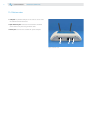
2 installation
when installing the Letrika communication gateway be aware that the micro inverter antenna and the Letrika
communication gateway antenna must be in the visible range and the distance between each other should not be more
than 30m. if this is not possible, please use the antenna extension cable.
Please follow next steps during the installation of Letrika communication gateway:
STEP 1
Attach the pylon to the wall using screws and hole-in
anchors.
STEP 2
Attach the other part of the pylon to the Letrika
communication gateway.
STEP 3
Attach the Letrika communication gateway to the wall
using the pylon.
STEP 4
Screw wMbus and wLan antennas to the wMbus
antenna connector and wLan antenna connector on the
Letrika communication gateway.
STEP 5
insert SD card into SD card slot. Note that SD card is not
included in the package.
STEP 6
connect Letrika communication gateway to the power
adapter. Letrika communication gateway can be used when
the communication gateway status LED turns green.
STEP 7
Remember the network iP that can be found at the
Network info menu on the Letrika communication gateway
LcD screen (use Menu keys for navigation).
STEP 8
connect your Pc/tablet/smart phone to the wifi/Ethernet
network and start your preferred web browser.
STEP 9
insert the network iP from step 7. into the URL bar of your
preferred web browser and the Setup wizard should start
automatically.
7
8
USER MANUAL
SEtUP wizARD
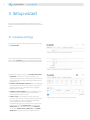
3 Setup wizard
First access to the web application will automatically start
the setup wizard which consists of two steps that you have to
follow.
3.1 gateway settings
choose the name for your power station and enter it into the
field PLANT NAME.
Figure 6: choosing the name for your power station
if you would like to activate username/password protection,
mark the field SECURITY and enter username and password.
you can later easily change your password at the same page.
Figure 7: Activating username/password protection
For additional settings mark the field ADVANCED SETTINGS.
• TIMEZONE: if Letrika communication gateway is not
connected to the internet, manually choose the timezone in
which Letrika communication gateway is located from the
dropdown menu.
• HARVEST MEASUREMENT INTERVAL: From the dropdown
menu choose how often the current power measurement
and the current energy measurement will be updated.
Default value is 1 minute.
• HARVEST STATUS INTERVAL: From the dropdown menu
choose how often the power station's status will be
checked. Default value is 1 minute.
• EXPORT TYPE: if you would like to export your power
station's measurements choose the export service provider
from the dropdown menu. currently supported export
service providers are Sitel and MoiDoM.
if you decide to export your measurements to Sitel, enter
www.pomse.si into the EXPORT HOST field and fill the
EXPORT URL field. otherwise, if you choose MOIDOM,
fill the fields EXPORT HOST, EXPORT URL and EXPORT
MOIDOM ID with values that were assigned to you by
Figure 8: Advance Letrika communication gateway settings
SEtUP wizARD
USER MANUAL
MOIDOM. we encourage you to use the first one and use portal
at the https://www.letrikasol.com to check the export data.
• EXPORT INTERVAL: if you chose one of the export service
providers, you can select how often the measurements will be
exported to the choosen export service provider. Default value
is 5 minutes.
After you have finished with gateway settings click on the SAVE
AND CONTINUE button.
3.2 Plant settings
if you set all the gateway settings from the previous
paragraph correctly, you will be redirected to the Plant settings
and the name of your power station will already be shown at
the top of the page.
Firstly define the size of your power station's micro inverter
table in the Advanced settings. the size of the table should be
defined in a way, that you will later be able to fill the fields of it
with micro inverters - each micro inverter at the same position
in the micro inverter table as it stands in your power station.
Micro inverters are then registered by filling the fields of the
micro inverter table with eight-digit micro inverter iD. For each
micro inverter its iD can be found on the label attached to it.
we suggest that you take the labels from the micro inverters
and paste them in to the micro inverter table which can be
found at the end of the Quick install guide included in the
package.
Each time after you fill the single field in the micro inverter
table with the new micro inverter iD and you move the focus
out of the field, the field will be disabled and underneath you
will notice a small blue box "registering...". if the micro inverter
has been successfully registered, the box will turn green
("registered"). otherwise, if the registration has not succeed,
an alert with an explanation will appear at the top of the page
and the field in the micro inverter table will be enabled again,
allowing you to correct it.
After the first micro inverter has been successfully registered,
its maximal output power will appear in the field MAXIMAL
OUTPUT POWER. the value in this field will later automatically
increase after the registration of each new micro inverter. you
can also set maximal output power manually.
the other two settings that you are able to change are POWER
FACTOR and PRICE. the POWER FACTOR is the ratio of the
real power and the apparent power, while PRICE represents
the price for 1kwh of energy.
After you have finished with plant settings click on the SAVE
button and the settings will be applied to all the registered
micro inverters.
Figure 9: Registering new micro inverters and setting other plant settings
9
10
USER MANUAL
MAiN PAgE
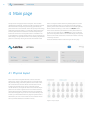
4 Main page
the top of the main page consists of two parts, which are both
updated every 60 seconds. the one on the left is showing numerical
informations about the quantity of the energy produced by the
power station since its installation, about the quantity of the energy
produced by the power station in a current day, about the earnings
since the power station's installation, and about the quantity of
reduced co2 emissions since the power station's installation. the
income depends on the price setting that the user can change at the
Plant settings. the right field contains a chart showing the produced
power in a current day. clicking on the chart with the left mouse
button, changes the shown data from produced power in a current
day to the produced energy in a current day. A blue dot is always
pointing at the current time at the Letrika communication gateway.
Above the field containing a chart there is an ON/OFF button,
which can be used when you decide to turn the power station on
or off. on its right side there is a STATUS light, which is coloured
green when the power station is on and coloured grey when power
station is off or when at least one of the micro inverters is sending
a warning or an alarm.
there are 5 different views to chose among at the Main page.
Figure 10: overview of the power station
4.1 Physical layout
Each micro inverter is represented with a circle at the same
position as it stands in your power station. the numbers show
the produced energy and current power for each inverter, while
the number of lines and their colours show the ratio of micro
inverter output power and its status. the higher that the
number of lines is, the higher the ratio of micro inverter output
power is. if some alarm appears at the micro inverter the lines
will be coloured red and an additional box with the explanation
of the error will appear. if you click on the circle of working micro
inverter, you will be redirected to the page with panel statistics.
otherwise, if you click on the circle of the micro inverter with an
alarm you will be redirected to the Alarm history.
Figure 11: Physical layout
MAiN PAgE
USER MANUAL
4.2 Matrix layout
Micro inverters are arranged by their micro inverter table number
(where empty places are left out). the meaning of the numbers,
lines, and colours is the same as in the Physical layout.
Figure 12: Matrix layout
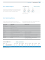
4.3 Panel statistics
current status and the last measurements for each micro
inverter are gathered in the table. if you click on an alarm iD, you
will be redirected to the Alarm history. the interpretation of the
measurements can be found in the next table.
Measurement
Interpretation
Expected values
Panel iD
Panel iD
-
Micro inverter iD
Micro inverter iD
-
time
Measurement timestamp
-
Status
Status
on
Hw ver.
Micro inverter hardware version
-
Sw ver.
Micro inverter software version
-
Max Power
Maximal output power of the micro inverter
Depends on user settings
cos phi
Ratio of the real and apparent power
Depends on user settings
Freq.
Frequency
Approximately 50hz.
Dc-Dc t.
temperature at the Dc side of the micro inverter
Depends on the mounting frame heat dissipation
Dc-Ac t.
temperature at the Ac side of the micro inverter
Depends on the mounting frame heat dissipation
Sec Dc volt.
Voltage at the secondary Dc side
Approximately 400V
Alarm iD
Alarm iD
0 (For detailed description of alarm iD see the
Micro inverter user manual.)
Figure 13: Panel statistics
11
12
USER MANUAL
MAiN PAgE
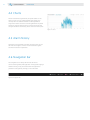
4.4 charts
All the measurements gathered at your power station can be
seen as a chart. you can choose between daily, weekly, and
monthly view. the selection between the data gathered at
single micro inverter and the sum of data gathered at the power
station can also be made. By clicking on arrows on the left and
the right side of the shown date, you can also check history data.
Figure 14: charts
4.5 Alarm history
All the alarms are gathered in the table. For every alarm you can
see when did it happen, on which micro inverter did it appear,
and what kind of error it represents.
4.6 Navigation bar
the navigation bar can always be found at the Letrika
communication gateway web application. Among other language
selection and log out (if you activated username/password
protection at the gateway settings) can be made there.
Figure 15: Navigation bar
SEttiNgS
USER MANUAL
5 Settings
All the setting that were set in the Setup wizard can later be changed
at the Settings.
5.1 gateway settings
5.2 Plant settings
Basic gateway settings are the same as in the Setup wizard.
Basic plant settings are the same as in the registration wizard.
Each new micro inverter should be registered via this page.
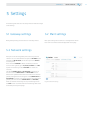
5.3 Network settings
Here you can set how the gateway will connect to your home
network. you can chose between two options: LAN MODE (static
or DHcP) and WLAN MODE (connected to your home WLAN or
as access point).
if the value for LAN MODE is DHcP (as default) the Letrika
communication gateway gains IP, MASK, GATEWAY, and DNS
by itself. All the settings under LAN MODE can also be set
manually.
the default CONNECTED IP for WLAN MODE is 192.168.50.1. if
the user insert the CONNECTED IP for WLAN MODE into the
URL bar of his preferred web browser the Letrika communication
gateway web application should appear. if the CONNECTED IP for
WLAN MODE is changed, it can be found at the LcD screen of the
gateway (the same is true for CONNECTED IP for LAN MODE).
when you are done with changes at any of the settings click on
the SAVE button. you will be informed if the settings were saved
successfully at the top of the page.
Figure 16: Network settings
13
USER MANUAL
14
SEttiNgS
5.4 Plant settings via LcD screen
Plant settings can also be changed via LcD screen on the Letrika
communication gateway. Use the menu keys to register new
micro inverters.
Registration of micro inverters via LCD screen
1.
the default view on the LcD screen is Plant info.
2.
click on the DowN key once to move to the Plant settings view.
3.
click on the Enter key twice to be able to register new micro inverter.
3.*
click on the Enter key, DowN key, and Enter key to be able to import
micro inverter.
4.
Use the Enter key to select the numbers and letters, and the UP and
DowN keys to navigate through the iD when inserting micro inverter iD.
5.
when you have entered micro inverter iD, click on the Enter key and if
the registration succeeded "Registered." will be displayed and you will
be redirected to the inverter info view.
tEcHNicAL cHARActERiSticS
USER MANUAL
6 technical characteristics
Communication to micro inverters
WMbus 868 MHz complies to EN 13757-1 . . . 5, selectable sample rate (Min. 60 s)
Communication to PC, tablet, smartphone
WiFi IEEE 802.11 / 2.4 GHz, Ethernet RJ45
Connectors
RJ45 Ethernet, USB (for additional functions)
Optional
Sending data to cloud by predefned protocol
Operating system
Embedded Linux, Integrated web server
Data storage
SD card (Max. 32 GB)
Basic monitoring and settings
Through LCD display
IP protection
IP 40
Ambient temperature
-20 °C . . . + 55 °C
POWER SUPPLY:
Input
100 Vac - 240 Vac; 50 Hz - 60 Hz
Output
12 Vdc, 700 mA
Optional
Extension cable for WMbus antenna
Dimensions
150 x 37 x 155 mm
Weight
350 g
15
16
USER MANUAL
coNtActS
contacts
Letrika Sol d.d. is a joint venture between cosylab d.d. and Letrika d.d..
Headquarters
Letrika Sol d.o.o.
Vrtobenjska 64
5290 Šempeter pri gorici
Slovenia
E: [email protected]
www.letrikasol.com
t: 00386 5 339 4262
SMS Metering Ltd
41 London Road, Castle Court, Reigate RH2 9RJ
TEL: 0845 604 7244
E-mail: [email protected]
Web: www.smsmetering.co.uk