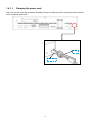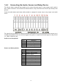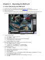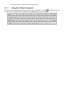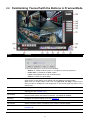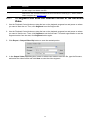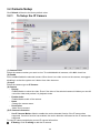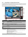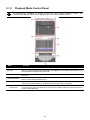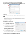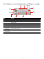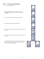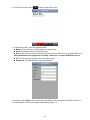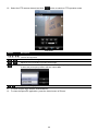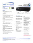
1
NVRP4 User’s Manual July 2012 FCC NOTICE This device complies with Part 15 of the FCC Rules. Operation is subject to the following two conditions: (1) this device may not cause harmful interference, and (2) this device must a ccept any interference received, including interference that may cause undesired operation. Federal Communications Commission Statement NOTE- This equipment has been tested and found to comply with the limits for a Class A digital device, pursuant to Part 15 of the FCC Rules. These limits are designed to provide reasonable protection against harmful interference in a residential installation. This equipment generates uses and can radiate radio frequency energy and, if not installed and used in accordance wi th the instructions, may cause harmful interference to radio communications. However, there is no guarantee that interference will not occur in a particular installation. If this equipment does cause harmful interference to radio or television reception, which can be determined by tuning the equipment off and on, the user is encouraged to try to correct the interference by one or more of the following measures: Reorient or relocate the receiving antenna. Increase the separation between the equipment and re ceiver. Connect the equipment into an outlet on a circuit different from that to which the receiver is connected. Consult the dealer or an experienced radio/television technician for help. CE NOTICE This product is herewith confirmed to comply with the r equirements set out in the Council Directives on the Approximation of the laws of the Member States relating to Electromagnetic Com patibility Directive 2004/108/EC. Warning - This is a Class A product. In a domestic environment this product may cause radi o interference in which case the user may be required to take adequate measures to correct this interference. DISCLAIMER No warranty or representation, either expressed or implied, is made with respect to the contents of this documentation, its quality, performance, merchantability, or fitness for a particular purpose. Information presented in this documentation has been carefully checked for reliability; however, no responsibility is assumed for inaccuracies. The information contained in this documentation is subject to change without notice. TRADEMARKS All other products or corporate names mentioned in this documentation are for identification and explanation purposes only, and may be trademarks or registered trademarks of their respective owners. COPYRIGHT All rights reserved. No part of this publication may be reproduced, transmitted, transcribed, stored in a retrieval system, or translated into any language in any form by any means without the written permission of the manufacturer. The mark of Crossed-out wheeled bin indicates that this product must not be disposed of with your other household waste. Instead, you need to dispose of the waste equipment by handing it over to a designated collection point for the recycling of waste electrical and electronic equipment. For more information about where to drop off your waste equipment for recycling, please contact your household waste disposal service or the shop where you purchased the product. Battery Safety Information - Store the batteries in a cool dry p lace. Do not dispose of used batteries in domestic waste. Dispose of batteries at special collection points or return to point of sale if applies. Remove the batteries during long periods of non-use. Always remove exhausted batteries from the remote control. Battery leakage and corrosion can damage this remote control, dispose of batteries safely. Do not mix old and new batteries. Do not mix different types of batteries: alkaline, standard (carbon-zinc) or rechargeable (nickel-cadmium). Do not dispose of batteries in a fire. The batteries may explode or leak. Never short circuit the battery terminals. WARNING TO REDUCE RISK OF FIRE OR ELECTRIC SHOCK, DO NOT EXPOSE THIS APPLIANCE TO RAIN OR MOISTURE CAUTION IF THERE IS ANY DAMAGE, SHORTAGE OR INAPPROPRIATE ITEM IN THE PACKAGE, PLEASE CONTACT YOUR LOCAL DEALER. WARRANTY VOID FOR ANY UNAUTHORIZED PRODUCT MODIFICATION NOTICE - INFORMATION IN THIS DOCUMENT IS SUBJECT TO CHANGE WITHOUT NOTICE. - THE INFORMATION CONTAINED HEREIN IS TO BE CONSIDERED FOR REFERENCT ONLY. Table of Contents Chapter 1 Introduction ..................................................................................................................... 1 1.1 Package Content ....................................................................................................................... 1 1.2 Front Panel ................................................................................................................................ 2 1.3 Back Panel................................................................................................................................. 2 1.4 Setting Up the NVR Unit ............................................................................................................ 4 1.4.1 Connecting Devices .............................................................................................................. 4 1.4.1.1 Clamping the power cord................................................................................................... 5 1.4.2 Connecting the Audio, Sensor and Relay Device .................................................................. 6 Chapter 2 2.1 Operating the NVR unit ................................................................................................... 7 First Time Using the NVR Unit ................................................................................................... 7 2.1.1 2.2 Using the Virtual Keyboard .................................................................................................... 8 Familiarizing Yourself with the Buttons in Preview Mode ............................................................ 9 2.2.1 Setting Up and Using the Emap .......................................................................................... 11 2.2.1.1 To Set Up the Emap ........................................................................................................ 11 2.2.1.2 To Use the Emap ............................................................................................................. 11 2.2.2 Familiarizing Yourself with the Buttons in PTZ Camera Controller ....................................... 12 2.2.2.1 Setup the IP PTZ Camera ............................................................................................... 13 2.2.3 2.3 Using Event Log Viewer ...................................................................................................... 14 Familiarizing Yourself with the Buttons in Playback Mode ........................................................ 15 2.3.1 To Segment and Save the Desired Portion of the Recorded Video ...................................... 17 2.3.2 To Bookmark a Video Section ............................................................................................. 18 2.3.3 Using the Event Search....................................................................................................... 19 Chapter 3 Customizing the NVR System ...................................................................................... 20 3.1 System Setup .......................................................................................................................... 20 3.2 Camera Setup .......................................................................................................................... 25 3.2.1 To Setup the IP Camera ...................................................................................................... 25 3.2.2 To Setup Camera from the Remote NVR............................................................................. 29 3.3 Recording Setup ...................................................................................................................... 30 3.4 Network Setup ......................................................................................................................... 32 3.5 Schedule Setting ...................................................................................................................... 35 3.6 Backup Setup .......................................................................................................................... 36 3.6.1 Using QPlayer to Playback Backup Video ........................................................................... 37 3.6.2 To Segment and Save the Desired Portion of the Recorded Video ...................................... 40 3.6.3 Using the Visual Search ...................................................................................................... 40 3.6.4 To Search Using the Event Search ...................................................................................... 41 3.6.5 To Search Using the Intelligent Search ................................................................................ 42 3.7 Sensor Setting ......................................................................................................................... 43 3.8 Relay Setting ........................................................................................................................... 44 3.9 Alarm Setting ........................................................................................................................... 45 3.10 User Setup ............................................................................................................................... 49 Chapter 4 Using the USB Playback Console ................................................................................ 51 4.1 Recommended system requirements ....................................................................................... 51 4.2 Installing the USB Playback Console ....................................................................................... 51 4.3 Running the USB Playback Console ........................................................................................ 52 4.3.1 To Segment and Save the Desired Portion of the Recorded Video ...................................... 54 4.3.2 Playback NVR Recorded File from Hard Disk ..................................................................... 55 4.3.3 Playback Backup File(*.dvr) ................................................................................................ 56 4.3.4 To Backup Recorded File .................................................................................................... 57 Chapter 5 5.1 Using the Remote Programs ........................................................................................ 58 Familiarizing the Buttons in PCViewer...................................................................................... 59 5.1.1 PCViewer Screen ................................................................................................................ 59 5.1.2 PCViewer Control Panel ...................................................................................................... 60 5.1.3 Playback Mode Control Panel ............................................................................................. 62 5.1.4 To Setup Remote System Setting ........................................................................................ 64 5.1.4.1 System Setting ................................................................................................................ 64 5.1.4.2 Camera Setting ............................................................................................................... 65 5.1.4.3 Record Setting ................................................................................................................ 68 5.1.4.4 Network Setting ............................................................................................................... 70 5.1.4.5 Alarm Setting ................................................................................................................... 72 5.2 Familiarizing Yourself with the Buttons in Remote Console ...................................................... 76 5.2.1 To Setup Remote Console Setting....................................................................................... 77 5.2.2 Familiarizing Yourself with the Buttons in PTZ Camera Controller ....................................... 78 5.3 Using the Remote Playback ..................................................................................................... 79 5.3.1 Familiarizing Yourself with the Buttons in Local Playback .................................................... 80 5.3.1.1 To Cut and Save the Wanted Portion of the Recorded Video ........................................... 82 5.3.2 Familiarizing Yourself with the Buttons in RealTime Playback ............................................. 83 5.3.3 Familiarizing Yourself with the Buttons in Download and Playback ..................................... 85 Chapter 6 6.1 Using Mobile Device to Access NVR Server ................................................................ 86 Using PDAViewer to Access NVR Server ................................................................................. 86 6.1.1 To install PDAViewer thru ActiveSync .................................................................................. 86 6.1.2 To install PDAViewer from the Internet ................................................................................ 86 6.1.3 To Use the PDAViewer ........................................................................................................ 87 6.1.4 To Playback in PDAViewer .................................................................................................. 88 6.2 Using JavaViewer to Access NVR Server ................................................................................ 89 6.2.1 To install JavaViewer from the NVR Server ......................................................................... 89 6.2.2 To Use the JavaViewer ........................................................................................................ 90 6.3 Using iPhone to Access Remote NVR Server .......................................................................... 91 6.3.1 Download the SpecoPC Application .................................................................................... 91 6.3.1.1 Download through the PC ............................................................................................... 91 6.3.1.2 Using iPhone to Download .............................................................................................. 92 6.3.2 Using the SpecoPC Application ........................................................................................... 92 6.3.3 To Preview the Live Video on iPhone .................................................................................. 96 6.3.4 Using the SpecoPC to Palyback on iPhone ......................................................................... 99 Chapter 7 7.1 Web Tools .................................................................................................................... 102 Remote Setup ........................................................................................................................ 102 7.1.1 To Add NVR server ............................................................................................................ 102 7.1.2 To Setup Remote System Setting ...................................................................................... 103 7.2 7.2.1 Remote Backup ..................................................................................................................... 104 To back up the recoded data from the NVR server: ........................................................... 104 Appendix A Registering Domain Name ........................................................................................... 107 Chapter 1 Introduction NVRP4 brings you the new version of pure NVR. With Compact size, it provides 4 channel video and audio inputs. Shattering marketing limitation by supporting full range of IP camera from all major manufactures worldwide and accepting H.264, MPEG4 and MJPEG video streaming format. 1.1 Package Content (1) (6) (2) (3) (4) (5) (7) (8) (1) NVRP4 unit (2) Software CD (User Manual included) (3) Quick User Guide (4) USB optical mouse (5) Power Cord (6) Power Adapter (7) Clamp(see Chapter 1.4.2.1 for installation) (8) Warranty card i If there is any damage, shortage or inappropriate item in the package contents, please contact your local dealer 1 1.2 Front Panel Name Function (1) NVR Power LED Light when the unit is power on (2) HDD LED Indicate the hard disk running state. Light when the HDD is running (Read/Write) (3) IR Sensor Receive signal from the remote control to operate the unit (4) USB 2.0 Port For flash drive/DVD-ROM connection (5) Network 1 Indicator Indicate the status of network 1(Port LAN 1) (6) Network 2 Indicator Indicate the status of network 2(Port LAN 2) 1.3 Back Panel Name Function (1) 2* USB 2.0 ports For USB keyboard, mouse, and other USB devices connection. (2) VGA Out Output the video signal to a CRT or LCD monitor (3) Audio In/Out - Audio In: Input the audio signal from audio input device such as microphone Audio Out: Output the audio signal to a audio out device such as speaker i The audio input/output device has its own power supply is necessary. (4) Sensor In Support 4 sensor devices (5) Alarm Out Support 1 relay device (Relay: 1A @ 125V AC/30V DC) (6) e-SATA port For connecting external RAID (7) Gigabit LAN 1 port - (8) Gigabit LAN 2 port - (9) Power button i LAN connection only but default assign as a DHCP service port. User also can connect the IP camera through the Ethernet cable. LAN 1 supports Static and DHCP mode. To connect the switch of your network for internet connection, remote accessing, and connection of IP camera. LAN 2 support Static, DHCP, and PPPOE mode. Press it to power on the NVR unit. To shutdown the fan, please disconnect the power cord cable from NVR unit. (10) 12V DC Power cable connection 2 Name Function (11) Clamp hole For clamp plug-in to clamp the power cord(see Chapter 1.4.1.1) (12) Lock hole For locking the NVR unit to avoid NVR unit been taken. 3 Setting Up the NVR Unit 1.4 1.4.1 Connecting Devices The back panel of the NVR unit, user can connect the 4 sensor devices, 1 alarm device, audio input/output device and an external HDD storage device. Through the two Gigabit LAN ports can balance the network bandwidth for IP camera connection and remote accessing. The USB ports can connect the mouse and keyboard for more easily to operate NVR server. Follow the illustration below to make the connection: i - Both two LAN ports can be connecting with IP camera and remote accessing. To complete shutdown (power off NVR unit and fan) the NVR unit, please disconnect the power cord cable from NVR unit. 4 1.4.1.1 Clamping the power cord User can use the clamp that included in package content to clamp the power cord that prevents external force to slide the power cord. Clamp Power cord 5 1.4.2 Connecting the Audio, Sensor and Relay Device The Sensor, Alarm, and audio port enable you to connect 4 sensor inputs, 1 relay outputs, and 1 audio in and 1 audio out device. Just connect the external sensor, relay, and audio in/out device pin directly to the pinhole. Check the table below and locate which pinhole is assigned to sensor input, relay output, and audio in/out. The signal from the sensor (i.e., infrared sensors, smoke detectors, proximity sensors, door sensors, etc.) is being transmitted to the unit and this triggers the system to respond and send signal to relay device (i.e., alarm, telephone etc). Audio in and out pinhole: Pin # 1 2 3 4 Definition Audio input signal Audio Ground signal Audio output signal Audio Ground signal Pin # 5 6 7 8 9 10 11 12 13 14 Definition Sensor 1 signal Sensor 1 Ground signal Sensor 2 signal Sensor 2 Ground signal Sensor 3 signal Sensor 3 Ground signal Sensor 4 signal Sensor 4 Ground signal Relay signal Relay signal Sensor and Alarm pinhole: 6 Chapter 2 Operating the NVR unit 2.1 First Time Using the NVR Unit 1. 2. 3. 4. Connect the mouse to the USB port located at front panel of the NVR unit. Using the mouse and virtual keyboard (see also Chapter 2.1.1) to operate the NVR system. Power on the NVR unit. For security purpose, the NVR system would require you to enter User ID and Password before it can be accessed. (If this is the first time, enter the default ID [admin] and password [admin]). Preview UI 5. Formatting the hard disk. a. Click Setup and enter the password b. Click System → Add c. Select the hard disk from device list and select Format type d. Click Format button to start formatting e. When formatting is done, click OK. 6. Setup the date and time in order to have correct recording time and date. a. Click Setup and enter the password b. In Time section, click Setting button of System Time. c. Select the date and adjust the time, and then, click OK. 7. Connect the IP camera. a. Click Setup → Camera b. Select camera channel and type of camera – IP Camera c. And then, enable the camera d. Click IP Setting e. Enable Protocol, and then, select protocol, mode, video format, and channel of IP camera. f. Enter IP address or URL of IP camera. g. Enter ID and password if IP camera’s access authority is required. h. Click OK. 7 i. 2.1.1 To connect another IP camera, follow the above steps. Using the Virtual Keyboard User can use the Virtual Keyboard when the keyboard is not available. Just click or right-click screen to call out the virtual keyboard. For uppercase, click Caps button. To exit, click Esc. 8 2.2 Familiarizing Yourself with the Buttons in Preview Mode Name Function (1) Exit Call up the Logout dialog box. (2) Split Screen Mode In the logout dialog box, you may do the following: - Reboot: To restart the NVR system. It is required to enter the password - Power OFF: To shutdown the NVR system. - Login: Using different ID to login to NVR system. - Cancel: To close the logout dialog. Select from 2 different split screen types to view all the cameras or one camera on a single screen. It also allows you to switch and view different camera number. When user is in single screen mode, user can right-click and drag a square on the area you want to enlarge the view. Right-click on the screen again will return to the normal view. Start/stop video recording. (3) Record (4) EMap (5) Network Display the map in each area, and the location of camera/ sensor/ relay and the warning (see also Chapter 2.2.1). Enable/disable remote system access. This feature allows you to access NVR server from a remote location via internet connection. The default is disabled. (6) Setup Configure the system settings. (see also Chapter 3) (7) PTZ To call out the PTZ control panel(see also Chapter 2.2.2) (8) Preview Switch to Preview mode. This allows you to view live camera display. (9) Playback Switch to Playback mode. This allows you to view the recorded video file. (see also Chapter 2.3). (10) Status bar Display the recoding date, time and hard disk space of NVR unit. 9 Name Function (11) Camera ID (12) Snapshot Show the number of cameras that are being viewed. When you are in single screen mode, click the camera ID number to switch and view other camera. Capture and save the screen shot in *.jpg format. (13) Event log Show the record of activities that take place in the system. (see also Chapter 2.2.3) (14) AutoScan Start/Stop video screen cycle switch. (15) Full screen View in full screen. To return, press the right button of the mouse or ESC on the keyboard or click the arrow icon. Click to exit from full screen mode When you switch to full screen in multiple-screen mode, Left click to toggle to only display one of the video in the multiple-screen mode or all. (16) Alarm Alert and display warning information. (17) Virtual Keyboard If the keyboard is not available, you may use the virtual keyboard. 10 2.2.1 Setting Up and Using the Emap E-Map can hold up to 8 maps in *.jpg format. You may locate the camera, sensor and relay on the map. 2.2.1.1 To Set Up the Emap 1. Click Emap. 2. When the Emap screen appears, click the area number (1 to 8 buttons) on where you want to insert the map. 3. Click Load Map to insert the map. When the open dialog box appears, locate and select the map and click Open. 4. When the inserted map appears on the Emap screen, click Edit. You may now drag the camera, sensor, and relay icons to its place on the map. Icons on the map can be relocated anywhere. If you are going to locate the icon on the map to other area, you need to drag the icon to the black pane at the bottom of the Emap screen and then switch to the area on where you want to locate the icon. To bring all the icons back to the black pane at the bottom of the Emap screen, click Reset Icon. 5. When you are done, click Save button to save the new setting. To exit Emap screen, click Close. 2.2.1.2 To Use the Emap 1. Click E-map. 2. In the Emap screen, click the camera icon to switch on the area where the camera is located on the map and to display the video at the upper right corner of the Emap screen. At the lower right corner of the Emap screen, it lists all the warning message. 3. To view different Emap, click Emap number button (1 ~ 8). 4. Click Close to exit Emap screen. 11 2.2.2 Familiarizing Yourself with the Buttons in PTZ Camera Controller (6) (5) (4) (3) (7) (2) (1) (11) (8) (9) (10) Name Function (1) Setup Configure PTZ cameras.(see also Chapter 2.2.2.1) (2 Close (3) AutoPan Exit PTZ camera controller. Operate the PTZ cameras automatically based on the selected camera group preset position number. Adjust the focus manually to produce clear image. Zoom in and out the image. Adjust and position the focal point of the PTZ camera. Display the PTZ camera number that is being operated. Save the PTZ camera preset position number. Select the camera and click the preset position number and save it. (4) Focus +/(5) Zoom +/(6) Direction buttons (7) Camera ID pane (8) Save Camera preset position (9) Camera lens speed controller (10) Camera preset position number (11) Group AutoPan Adjust the moving speed of the PTZ camera lens. Move the PTZ camera to the preset point. Select to automatically operate PTZ camera in group. 12 2.2.2.1 Setup the IP PTZ Camera When IP PTZ camera has successful connected with the NVR system, user can use the PTZ function directly without any configuration. To make connection of IP PTZ camera, please refer to Chapter 3.2.1. In PTZ camera panel, user can setup the preset position of the camera. The number of preset positions are depend on the IP PTZ camera that user has connected. For example: A brand of IP PTZ camera only supports 4 preset positions. Therefore, user only can setup 4 preset positions on the NVR system. User can refer to the user’s manual of the IP PTZ camera to make sure the number of the preset positions has supported. Please follow the below steps to configure the preset position. 1. On Preview UI, select the channel that is an IP PTZ camera connection. 2. Click PTZ button from Preview UI and PTZ control panel will show up. 3. In the PTZ control panel, using the arrow button to adjust the position of IP PTZ camera. 4. And then, click Setup (see also Chapter 2.2.2). The Preset Settings window will show. 5. Select the Preset Number to assign a number for the PTZ camera current position. And then, click Save to save the setting. 6. Set the DwellTime for how long the PTZ camera stays in that position before it moves to the next one. 7. Repeat step 3 to 6, if you want to save another preset position. 8. Restore AutoPan Time: set a time period for restoring auto path function after the PTZ camera has been moved manually. Mark the check box and set the time period in second. 9. Click OK to complete the setting. 13 2.2.3 Using Event Log Viewer Show the record of activities that take place in the system. 1. Click the Event Log button on NVR system main interface. The Event log viewer window will show up. 2. Select the Date to view. 3. To filter the records, select and click the select button to display Event, System, Operation, Network or All. 4. Use the scroll button to go next, previous, first, or last page ( , , , )of event list. 5. To find event log by keyword, enter keyword in Find Text column and click Search. 6. The events list which display on the screen can be saved as text file format. To save the events list, click Save button. 14 2.3 Familiarizing Yourself with the Buttons in Playback Mode To switch in Playback mode, click Playback button at the lower right corner of Preview mode user interface. Name (1) Split Screen Mode (2) Progress bar (3) Hour Buttons i Function Select from 2 different split screen type to playback the recorded video file of all the camera or one camera on a single screen. When user is in single screen mode, user can right-click and drag a square on the area you want to enlarge the view. Right-click on the screen again will return to the normal view. Show the progress of the file being played. You may move the bar to seek at any location of the track. Select and click to playback the recorded video file on the specific time frame. The Hour buttons represent the time in 24-hour clock. The blue bar on top of the hour button indicates that there is a recorded video file on that period of time. While the red bar indicates that you are currently viewing the recorded video file. (4) Playback Control Buttons From left to right order: Begin: Move at the beginning of the recorded video file. Previous: Go back to the previous frame. Slower: Play the recorded video file at the reduce speed from 64x, 32x, 16x, 8x, 4x, 2x, 1x, 1/2x, 1/4x. Rewind: Wind back the recorded video file. Pause: Briefly stop playing the recorded video file. Play: Play the recorded video file. Faster: Play the recorded video file at the speed of 2X, 4X, 8X, 16x, 32x, or 64x. Next: Go to the next frame. End: Go to the end of the recorded video file. 15 Name (5) Date i Function Select the date on the calendar and the time from 00 to 23 to where to start playing the recorded video file. The numbers from 00 to 23 represent the time in 24-hour clock. The numbers from 01 to 04 represent the camera ID. The blue colored column indicates that there is a recorded video file on that period of time. While the red colored column indicates on where to start playing the recorded video file. (6) Preview (7) Playback (8) Status bar (9) Camera ID (10) Export (11) Segment (12) Full screen Switch to Preview mode. Switch to Playback mode to view the recorded video file. Display the recorded date, time and play speed. Show the number of cameras that are being viewed. When you are in single screen mode, click the camera ID number to switch and view other camera. Export includes Snapshot, Output Video Clip, and Backup function. Snapshot: Capture and save the screen shot in *.jpg format. Output Video Clip: Save the segmented file in *.dvr format to external USB storage device (see also Chapter 2.3.1). Backup: Save the playback file to external USB device or external DVD burner. Keep a portion of the recorded video (see also Chapter 2.3.1). View in full screen. To return, press the right button of the mouse or ESC on the keyboard or click the arrow icon. Click to exit from full screen mode (13) Event log (14) Bookmark When you switch to full screen in multiple-screen mode, Left click to toggle to only display one of the video in the multiple-screen mode or all. Show the record of activities that take place in the system. To filter the records, select and click the option button to only display Event, System, Operation, Network or All. Mark a reference point when reviewing the recorded video file to which you may return for later reference (see also Chapter 2.3.2). 16 Name (15) Find Next Function Search for the next event or changes in the motion detector frame. You can use this when you are using Event Search function. (16) Event Search Search from the recorded activities that were recorded in event log (i.e., Sensor, Motion, Video Loss)(see also Chapter 2.3.3) 2.3.1 To Segment and Save the Desired Portion of the Recorded Video 1. Use the Playback Control buttons or drag the bar on the playback progress bar and pause on where you want to start the cut. Then, click Segment to set the begin mark. 2. Use the Playback Control buttons or drag the bar on the playback progress bar and pause on where you want to end the cut. Then, click Segment to set the end mark. To cancel segmentation or set the segment marks from the start, click Segment button again. 3. Click Export > Output Video Clip button to save the wanted portion. 4. In the Output Video Clip dialog box, locate on where user wants to save the file, type the filename, and select the video format and click Save to save the video segment. 17 2.3.2 To Bookmark a Video Section 1. Click Bookmark button 2. In the Bookmark dialog box, you may do the following: - Add to create the new reference mark in the bookmark list. In Bookmark Editor window, enter the name or a short description in Mark column for this bookmark. - Edit to change the mark description. - Delete to remove the selected reference mark in the list. - Delete All to remove all the reference marks in the list. - Exit to close Bookmark dialog box. 3. Select and click one in the bookmark list to review the file. 18 2.3.3 Using the Event Search 1. Click on the video screen on where you want to search. 2. Click Event Search. The Event Search Setting dialog box would appear on the screen. 3. In the Event Search Setting dialog box, check the type of condition you want to search. Then, click OK to start searching. The video search would stop at the frame that matches the condition. To keep on searching click Find Next( ) button. 4. You may also set to search and list all the result. Set the Begin Time and End Time. Set the Searching Interval time for during the interval time if system has found same event and will not list out. Then, click OK to start searching. i The NVR system will set the date of End Time at 3 days later of Begin Time automatically. If event data are less than 3 days, the NVR system will set End Time at current date. Time of End Time is adjustable. 5. When the Event list appear, click and select the item you want to view. 19 Chapter 3 Customizing the NVR System In the Preview screen mode, click button to customize your NVR. Enter the ID and password to authenticate(Default ID is admin and password is admin). When the NVR configuration setup selection appears, select and click the buttons you want to change the setting. 3.1 System Setup In the System Setting dialog box, click OK to accept the new settings, click Cancel to exit without saving. (8) (1) (9) (2) (3) (4) (10) (5) (6) (11) (7) (1) Storage Path Set the HDD on where to save the data. In case you have more than one storage device, the system automatically saves the data to the next storage device. To insert another storage device, click Add and select the storage path. To remove the selected path, click Delete. If the hard disk is the first time for NVR system, please format the hard disk before starting to use it. To format the hard disk, click Add and select the hard disk and Format in Disk Management window, and then, click Format button. 20 (2) Delete recorded data after If you want the system to automatically erase the data after a certain days, enable the Delete recorded data after check box and enter the number of days in Days text box. (3) Delete event and alarm log after If you want the system to automatically erase the event and alarm log after a certain days, enable the Delete event and alarm log after check box and enter the number of days in Days text box. (4) Overwrite Enable When there is not enough free space to record one hour data, the system automatically replaces the oldest data. (5) Language Customize the system to display the tool tips and dialogs based on the selected language. Default language is in English. (6) Configuration Backup a copy of all the settings and allows you to regain the same settings back. To save the current settings, click Export. To replace the settings with the one you have saved, click Import. Import UI Export UI 21 (7) Touch Monitor When NVR server is connected with touch monitor, user needs to adjust touch monitor in order to work normally. 1. Connect the touch monitor with NVR server. 2. Turn on the NVR server and touch monitor power. 3. Select Setup → System → Touch Monitor → Adjust. 4. The adjusting window will show up. 5. 6. Click + one by one to complete the adjustment. To disconnect touch monitor, click Disconnect button first, and then, turn off the power of touch monitor and remove the connection between NVR server and touch monitor. (8) Miscellaneous Playback mode: Select the mode of playback the video. – Select date and time: Select the date and time which user wants to playback. – Play the last file: Automatically playback the video from the last hour – Instant Playback: Automatically playback the video which has just recorded Date Format Select the date format which wants to display in select date and time playback mode Auto Scan Period Set the time gap of the Auto Scan function from 3 to 10 seconds. This automatically switches to the next video in cycle depending on the set time gap. (9) Login Enable the conditions in Login section you want the system to automatically carry out. Auto Login after system boot up Execute the NVR when the operating system is started. Auto Record after system boot up Automatically start video recording when the NVR is executed. Auto start Network after system boot up 22 Automatically start network connection when the NVR is executed. - Default user Automatically log in to the selected default user when the NVR is executed. (10) Date and Time Setting System Date and Time: Adjust the NVR system time and date. Click Setting button to select the month, date, hour, and minute. Daylight Saving: Mark Daylight saving check box to enable daylight saving function. And then, select the Start Date/Time and End Date/Time by click Setting button. Daylight Bias: Assign a time that it is for daylight saving time offset in your time zone. For example: if the time zone is in U.S. Eastern, the time offset is 1 hour. 23 (11) Firmware Product Version Update: Upgrading the firmware of NVR system. 1. Click Update button, a Firmware Upgrade window will show up. 2. Save the firmware on root directory of USB disk. And then, plug USB disk into NVR unit. 3. Select the USB disk if there is more than one USB disk from drop down list. The NVR unit will auto detects the firmware. The current firmware version will show in Current firmware version and the new firmware version will show in New firmware version. 4. Click OK to start upgrading. IPCam Module Update: Upgrading the firmware of IP camera. 1. Click Update button, a IPCam Module Firmware Upgrade window will show up. 2. Save the firmware on root directory of USB disk. And then, plug USB disk into NVR unit. 3. Select the USB disk if there is more than one USB disk from drop down list. The NVR unit will auto detects the firmware. The current firmware version will show in Current IP Cam Module version and the new firmware version will show in New IP Cam Module version. 4. Click OK to start upgrading. 24 3.2 Camera Setup Click Default will back to the factory default value. 3.2.1 To Setup the IP Camera (1) Camera Icons Select the camera number you want to view. To enable/disable all cameras, click ALL check box. (2) Enable Set to enable/disable the selected camera. When there is no video source on the camera, we suggest disabling it so that the system won’t detect it as video loss error. (3) Input Select the camera type as IP Camera. (4) Camera - Display Enable/disable to show the video. Even if the video of the selected camera is hidden you can still record the video and preview it in playback mode. - Enable Audio Enable/disable audio of the camera. - Name Change the camera name - Description Add a short comment (5) IP Camera Information - Use IP Camera Motion: Mark to enable the motion detected function if the IP camera has supported. Once this function has enabled, the motion detection will based on the IP camera has supported. To setup IP camera and display current IP camera information. IP Setting: Click IP setting to add the IP camera. 25 1. 2. 3. 4. 5. Click the radio button of Protocol to start setup IP camera. Select the Protocol, Model, Video Format, and Channel of the IP camera. Enter IP address and connecting port in IP Camera Site column. Also, user can enter URL of IP camera instead of IP address. If the IP camera has authority request, please enable Authentication and enter ID and Password. 6. Click OK to connect with the IP camera. Detail: To adjust IP camera parameters, click Detail. Click Default will back to the factory default value. User can select Video size, Frame rate, Bitrate mode and Quality of camera. Also, user can adjust Bright, Contrast, Hue, Saturation, and I/O Control of the camera. i The selection and adjustment items may vary by the camera supported. I/O Control: Setup the sensor and relay that is embedded on the IP camera. Sensor Setting 26 1. 2. 3. 4. Click Sensor button. Click the drop-down list and select the sensor ID number. Enter sensor name in Name column The system automatically detects the camera and input relates information. In the Content section, enter sensor Description. 5. In the test section, click Test to check the sensor status. Red is high and Green is low. 6. Click OK to exit and accept the setting and Cancel to exit without saving the setting. 27 Relay Setting 1. Click Relay button. 2. Click the drop-down list and select the relay ID number. 3. Enter relay name in Name column 4. The system automatically detects the camera and input relates information. In the Content section, enter relay Description. 5. In the test section, click Test to check the relay status. Red is high and Green is low. 6. Click OK to exit and accept the setting and Cancel to exit without saving the setting. 28 3.2.2 To Setup Camera from the Remote NVR User can add the camera from another NVR through the network. (1) Camera Icons Select the camera number you want to view. To enable/disable all cameras, click ALL check box. (2) Enable Set to enable/disable the selected camera. When there is no video source on the camera, we suggest disabling it so that the system won’t detect it as video loss error. (3) Input Select the camera type as Remote NVR. (4) Camera - Display Enable/disable to show the video. Even if the video of the selected camera is hidden you can still record the video and preview it in playback mode. - Enable Audio Enable/disable audio of the camera. - Name Change the camera name - Description Add a short comment - IP Enter the IP address of the camera - Port The port for connection - User ID Enter the user id that for connecting authority - Password 29 Enter the password that is for connecting authority - Channel Select the channel of connected camera - Connect Click to connect the camera when all configurations are set. 3.3 Recording Setup (1) Camera Icons Select the camera number you want to set the recording setting. To select all the cameras, enable the ALL check box. To select more than one camera, Right click on the camera icon. To select one camera only, Left click on the camera icon. The camera icon turns purple when it is selected. (2) Recording Mode The horizontal blocks from 00 to 23 represent the time in 24-hour clock and the vertical block 1 to 7 represent the day in the week block (Sunday to Saturday). To record in full 24 hours and 7 days a week, select the recording mode and click the button. If you want to only record at a particular time or day, click Schedule button and select the Recording Mode , and then click on the time or day blocks. When the system starts recording a red triangle mark would appear at the upper left corner of the screen. The recording modes are listed below: 30 - Always Recording Record the video from the selected camera and save it to the designated storage device - Motion Recording Start recording the video from the selected camera only when the system detects movement. Once a motion is detected, the system automatically saves the previous frames and stop based on the Start Record Prior and Stop Record After settings. - Smart Recording Automatically switch to recorded at the maximum frame rate setting once a motion is detected and if there is no motion, it records at the minimum frame rate setting. - No Recording The system won’t do any recording. (3) Motion Detection Adjust the sensitivity of the motion detection. The higher the value, the finer the sensitivity is detected. When it detects a motion, a green triangle mark would appear at the upper left corner of the screen. 31 3.4 Network Setup Click Default will back to the factory default value. (1) Server Name Assign a name for the NVR unit. Alphabet letters and numbers only. (2) Transmitting Cameras Select and click on the camera number in the Transmitting Camera section you want to make it accessible via internet using WebViewer, Remote Console, CMPC,PDA Viewer and JavaViewer (still image). To select all the cameras, enable the ALL check box. (3) Main Configuration Set the NVR IP address and Remote Console Port. You need this when accessing NVR server from the remote location via internet. The NVR system supports dual LANs; therefore, user can select the Server IP from the drop-down list and click setting to configure the detail. The dual LAN ports can balance network bandwidth to avoid the network traffic congestion. i - The default IP of the NVR server is 192.168.1.155 for LAN1 (lower LAN port in the back of the NVR) and 192.168.2.155 for LAN2 (upper LAN port in the back of the NVR). LAN1 and LAN 2 both support Static, DHCP, or PPOE mode. We recommend setting LAN 1 as a default gateway. 2 LAN ports cannot set in same LAN segment; it will cause the network connection failure. When only using port LAN2, please set IP address of port LAN 1 in different LAN segment from port LAN 2. 32 Using the following IP address: Assigns an IP address for the NVR system. Fill in the IP related parameters in IP information section. - IP: Assign a constant IP address which a real IP address gives from ISP to NVR system. - Mask: It is a bitmask used to identify the sub network and how many bits provide room for host addresses. Enter the subnet mask of the IP address which user has assigned to NVR system. - Gateway: A network device acts as a passageway to internet. Enter the network gateway IP address User only can setup one gateway for the NVR system. We do recommend setting the LAN 1 as default gateway and set the DDNS function within LAN 1 as well. i DNS: Domain Name Server translates domain names (such as www.abb.com.tw) to IP addresses. Enter the IP address of DNS if it is available. - MAC Address: An identifier hardware address of NVR unit that is assigned by the manufacturer for identification. User don’t need to fill in, it will generated by system automatically. Obtain an IP automatically (DHCP): Assign the IP address by local DHCP server to NVR system. PPPOE: Point-to-Point Protocol over Ethernet is a network protocol for encapsulating PPP frames in Ethernet frames. It is used mainly with ADSL services. If your network is using ADSL service connecting to internet, and then, select PPPOE mode. Enter User ID and Password that is given by your ISP for PPPOE connecting authority. DDNS: DDNS(Dynamic Domain Name Service) is a data query service mainly used on the Internet for translating domain names into Internet addresses. Users can register their own domain name on http://ddns.specoddns.net. (See Appendix A) - DDNS Server Name Displays the DDNS server. - DVR Name Enter the domain name (ex. NVRP4) that user wants to register in DVR Name column and click OK to confirm. Then, the NVR system will connect to DDNS server that list in DDNS Server Name column and register the domain name. If domain name registration is successful, no message will show up. User also can go to web site http://specoddns.net/ddns/query.asp to check the domain name registration status. - Web Server Port Fill in the port that connects to DDNS server. Default is 100. - EZ-DDNS Click EZ-DDNS button to get a domain name that is provided by NVR system and will not repeat with other registered domain name. User can use the domain name that is provided by NVR system or think your own. (4) Remote Upgrade Configuration A port is using for the remote firmware upgrade through network. - 33 (5) WebViewer Configuration Activate Enable Anonymous Login to remotely access the NVR server without the need of password. Fill in the WebViewer PORT for remote accessing connection. (6) Network Time Synchronization Adjust the NVR system time same as network time server. Fill in the Time Server IP address or domain name and select the Time Zone. User can enable Automatic Synchronize at to set automatic synchronize time on a daily basis. Or, user can click Synchronize Time Right Now to adjust time right away. (7) Other Configuration - Enable White List An access permit list for the remote accessing of NVR server. Enter the IP address and click Add. Or, enter a range of IP address and click Add. To delete the IP from the list, select the IP and click Delete button. To reset the input, click Clear button. - Network Bandwidth Limit By Channel: Set the network bandwidth by each channel. All: Set the total network bandwidth consumption limit. 34 3.5 Schedule Setting Schedule to record, enable network, reboot and disable alarm of all the cameras either weekly or one time. The number from 00 to 23 represent the time in 24-hour clock. The left most column display the days in a week. To Set the Schedule Setting: 1. Select the date in the calendar. Use and buttons to shift the calendar to the left or right. 2. Select the condition you want to schedule in the drop down list. - Record Activate all the cameras to start video recording at the set time based on the Recording setting - Enable Network Activate NVR remote system to access at the set time. After the appointed time, the Network function will be disabled. If the Network function is already enabled, the Network function will not be disabled when the appointed time has ended. - Reboot Restart the PC at the appointed time. - Disable Alarm Deactivate the alarm at the set time temporarily. 3. Set the schedule as weekly or one time. Click to make a selection. 4. Click on the blocks to set the schedule or click All to select all. To un-select the specific schedule blocks, click the Remove and click blocks to un-select. To store the setting, click Save. To remove the settings, click Clear. 5. To end Schedule Setting, click OK to exit and accept the setting and Cancel to exit without saving the setting. 35 3.6 Backup Setup In the Backup Setting dialog box, the number from 00 to 23 represent the time in 24-hour clock. The numbers from 01 to 04 represent the camera number. When you back up the file, you may find Qplayer application included in the backup folder. To run the Qplayer application, click Oplayer.exe in back folder. (see also Chapter 3.7.1) 1. Select the date of the recorded file in the calendar you want to backup. Use and buttons to shift the calendar to the left or right. 2. In the table above, click on the blue block to select the recorded file or click camera (01~04) or time (00~23) to select the whole row or column. The blue block turns red when it is selected. The block that appears in white doesn’t have data. If you want to set the specific time, right-click on the selected block. Then, set the time to start and end. 3. Check the space need for backup next to the calendar. Click Rescan Device to calculate the space for backup. – Require Space: Show the total size of the backup file. – Free Space: Show the available storage space 4. If you do NOT want to keep the recorded file in the storage folder, enable Delete files after Backup check box. 5. Select the backup device – USB disk or DVD-ROM device. 6. NVR system will give Folder Name automatically. 7. Click Backup Now button to start archiving the selected file. 36 3.6.1 Using QPlayer to Playback Backup Video You can playback the backup files using QPlayer applications on the PC. When you back up the recorded file, QPlayer applications are automatically included in the backup folder. With QPlayer, it is the same as in Playback mode and supports different split screen types to view all the video at the same time. The only difference is that there are no Preview and Playback buttons. To run the application, go to backup folder and double-click Qplayer .exe to run the QPlayer. Name Function (1) Exit To close the application (2) Split Screen Mode Select from 1 and 4-split screen type to playback the recorded video file. i If there are only 4 cameras, when user select the 8,9,13,and 16-spilt screen mode, only 4 channels have video display and rest of channels will be black screen. - To zoom in an area on the screen, Right click and Drag a square on the area you want to enlarge. - (3) Progress bar (4) Hour Buttons i Show the progress of the file being played. You may move the bar to seek at any location of the track. Select and click to playback the recorded video file on the specific time frame. The Hour buttons represent the time in 24-hour clock. The blue bar on top of the hour button indicates that there is a recorded video file on that period of time. While the red bar indicates that you are currently viewing the recorded video file. (5) Playback Control Buttons Begin: Move at the beginning of the recorded video file. Previous: Go back to the previous frame. Slower: Play the recorded video file at the speed of 1/2X, 1/4X, 1/8X, 1/16X, or 1/32X. Rewind: Wind back the recorded video file. Pause: Briefly stop playing the recorded video file. Play: Play the recorded video file. Faster: Play the recorded video file at the speed of 2x, 4x, 8x, 16x, or 32x. Next: Go to the next frame. End: Go to the end of the recorded video file. 37 Name Function (6) Archive Select the date on the calendar and the time from 00 to 23 to where to start playing the recorded video file. – Day Light Saving: the playback calendar will show the available video records during day light saving time period. – OPEN FILE: user can open the recorded file from other storage location on hard disk. – Channel 01~16/Channel 17~32: Click it to switch between channel group 01~16 and channel 17~32 on calendar if NVR server supports more than 16 channels. i The numbers from 00 to 23 represent the time in 24-hour clock. The numbers from 01 to 04 represent the camera ID. The blue colored column indicates that there is a recorded video file on that period of time. While the red colored column indicates on where to start playing the recorded video file. (7) Status bar (8) Camera ID (9) Language (10) Export (11) Segment Display the recorded date, time and play speed. Show the number of cameras that are being viewed. When you are in single screen mode, click the camera ID number to switch and view other camera. Customize the system to display the tool tips and dialogs based on the selected language. By default the language is in English. Export includes Snapshot, Print, and Output Video Clip function. Snapshot: Capture and save the screen shot either in *.jpg format. Print: Print the screen shot. Output Video Clip: Save the segmented file in *.dvr, *.avi, or *.mpg format. Keep a portion of the recorded video (see also Chapter 3.6.2). 38 Name Function (12) Full screen View in full screen mode. To return, press the right button of the mouse or ESC on the keyboard or click the arrow icon. Click to exit from full screen mode (13) Event Log (14) Visual Search (15) Find Next (16) Event Search (17) Intelligent Search (18) Audio (19) De-interlace When you switch to full screen in multiple-screen mode, Left click to toggle to only display one of the video in the multiple-screen mode or all. When backup, the NVR system will include event logs. User can view the record of activities that take place in the system. To filter the records, select and click the option button to only display Event, System, Operation, Network or POS. Search from a specific camera by Date, Hour, Minute, 10 Seconds and Second. (See also Chapter 3.6.3) Search for the next event or changes in the motion detector frame. You can use this when you are using Intelligent Search or Event Search function. Search from the recorded activities that were recorded in event log (i.e., Sensor, Motion, Video Loss). (See also Chapter 3.6.4) Search the changes in the motion detector frame (See also Chapter 3.6.5). Enable/disable volume To enhance the video quality. Set the de-interlace mode to #1, if you are capturing motionless picture and #2, if it captures lots of movement. 39 3.6.2 To Segment and Save the Desired Portion of the Recorded Video 1. Use the Playback Control buttons or drag the bar on the playback progress bar and pause on where you want to start the cut. Then, click Segment to set the begin mark. 2. Use the Playback Control buttons or drag the bar on the playback progress bar and pause on where you want to end the cut. Then, click Segment to set the end mark. To cancel segmentation, click Segment button again. 3. Click Export > Output Video Clip button to save the wanted portion. In the Save As dialog box, locate on where user wants to save the file, type the filename, and select the video format. 4. 3.6.3 Using the Visual Search 1. Click Visual Search. 2. In the Visual Search Setting dialog box, select the Camera number and the date. Then click OK. 3. When a series of frames appear by date, click on the frame to display another series of frames and search by every Hour of that date, every Minutes of that hour, 10 Seconds, 3 Seconds, and every Second of that minute. Using and to go next and last page of time page. To go back last time selection (hour, minute, or second), click . To close event search, click . 40 3.6.4 To Search Using the Event Search 1. Click on the video screen on where you want to search. 2. Click Event Search. The Event Search text (red) would appear at the lower left corner of the screen. 3. In the Event Search Setting dialog box, check the type of condition you want to search. The video search would stop at the frame that matches the condition. To keep on searching click Find Next ( ). 4. You may also set to search and list all the result. In the Search Duration section, set the Begin Time and End Time. Set the Searching Interval time that system won’t list out the same events in a period of time that user has setup. Then, click OK to start searching. 5. When the Event list appear, click and select the item you want to view. 41 3.6.5 To Search Using the Intelligent Search 1. Click on the video screen on where you want to search. 2. Click Intelligent Search. The Intelligent Search text (red) would appear at the lower left corner of the screen. 3. When the Intelligent Search Setting dialog box and motion detector frame appear, you may adjust the sensitivity bar and the motion detector frame size and location. To set motion detector frame size and location, left click and drag on the screen. Then, click OK to start searching. The video search would stop at the frame that matches the condition. To keep on searching click Find Next ( ). You may also set to search and list all the result. Just check the List box. In the Search Duration section, set the Begin Time and End Time. Set the Searching Interval time that system won’t list out the same events in a period of time that user has setup. Then, click OK to start searching. 42 3.7 Sensor Setting The I/O device must be installed to use this function. 1. The system automatically detects the I/O device that has connected with NVR system and display on the drop-down list column. Click the drop-down list and select the sensor that user wants to configure. 2. Enter sensor name in Name column. 3. In the Content section, enter Description of sensor. 4. In the test section, click Test to check the sensor status. Red is high and Green is low. 5. Click OK to exit and accept the setting and Cancel to exit without saving the setting. 43 3.8 Relay Setting The I/O device must be installed to use this function. 1. The system automatically detects the I/O device that has connected with NVR system and display on the drop-down list column. 2. Enter sensor name in Name column. 3. In the Content section, enter Description of relay. 4. In the test section, click Test to trigger relay. Red is high and Green is low. 5. Click OK to exit and accept the setting and Cancel to exit without saving the setting. 44 3.9 Alarm Setting In the Alarm Setting dialog box, click Add to insert and set new alarm setting, click Delete to remove the selected alarm setting, click OK to exit and save the setting, Cancel to exit without saving. Click Default will back to factory default value. 1. Click Add to insert and set a new alarm setting. Click the items in the (8) Alarm Setting List if you want to modify the alarm setting. 2. In (1) No./Name/Description enter alarm name and description. Alarm No. will be created by NVR system. 3. In (2) Enable Time, the number from 00 to 23 represent the time in 24-hour clock. Select the time and click the block you want to activate or deactivate the alarm function. When it is deactivated the color of the block turns white. 4. In (3) Conditions, you can set “Trigger if any” to activate if it falls to one of the conditions or “Trigger if all” to activate if it falls to all conditions. 5. In (4) Camera section, select and click on the camera number (01 to 04) in Motion Detected and Video Loss to set the condition for the system to alarm. 6. In (5) Sensor, select and click on the sensor number to set the condition for the system to alarm. If the sensor normal status is high, set the sensor condition to low. - IP Camera Sensor: To adjust sensor high/low that is connected on the IP camera. - Enable/disable the Abnormal Event check box, to set the condition of the event for system to alarm. 45 Reboot: when the NVR system reboot without abnormal condition, the system will send out the alarm message. Abnormal Reboot: when the NVR system reboot in irregular condition, the system will send out the alarm message. Recording is switched off: when the recording has been stopped, the system will send out the alarm message. Network is switched off: when the network connection of NVR system is lost, the system will send out the alarm message. Hard Disk failed: when the hard disk doesn’t work normally, the system will send out the alarm message. - Continue trigger duration: Set a time period that when sensor has been trigger and stay in the same status for that period, then the alarm will be sent out. 7. In (6) Alarm Reset, click the camera number to set the reset condition of alarm. Once alarm is reset, all alarm action will stop at the moment. If the sensor normal status is high, set the alarm reset condition to low. 8. In (7) Action, you may now set the alarm action for the system to perform when the alarm condition is activated. - Launch E-Map: Display mini E-map screen. - Enlarge Camera View Switch to only display video in Preview mode from where the alarm is activated. a. Select the camera from drop down list to specify which camera video to be enlarged on screen when the alarm is triggered. b. Retrieve time: set the waiting duration before system switching back to original Preview mode. If the retrieve time is un-mark, the alarm video will keep enlarging until user switch back to Preview mode manually. The retrieve time range is 0~ 600 seconds. 46 - Relay Output Set to enable/disable the relay operation when the alarm is activated and to extend additional time in second before it stops the relay operation. 1. Next to the Relay Output check box, click Detail. 2. In the Alarm Relay dialog box, select from the available relay list and in the ON column, set to enable/disable the relay operation when the alarm is activated. 3. In the Retrieve time check box, you may enable/disable to extend the relay operation time and set the duration in second. 4. Click OK to exit and accept the setting and Cancel to exit without saving the setting. - IP Camera Relay Set to enable/disable the relay operation when the alarm is activated. - Play Warning Sound Play alarm sound. - Send E-mail Send an electronic text message. Next to the Send Email check box, click Detail. In the E-mail Setting dialog box, click OK to exit and save the setting and Cancel to exit without saving the setting. (1) (2) (1) Mail Server Enter the SMTP Server and port. If your e-mail system requires user identification, enable Authentication check box and enter ID and Password. (2) Mail Fill the mailing information. From: Enter the sender e-mail address. To and CC: Enter the recipient email address and separate it with comma or a semicolon (;). Subject: Enter the message title. Message: Type the message. 47 - Start Recording Record the video from the selected camera. 1. Next to the Start Recording check box, click Detail. 2. In the Alarm Recording Setting dialog box, select the camera to enable/disable video recording. Enable All to select all cameras. 3. In the Frame Rate selection, select As Setting to record the number of frames based on the Recording Setting. 4. In the Start Record prior text box, mark and set the number in second for the program to begin recording after the alarm has been trigger. The time range is 1~10 seconds. 5. In the Stop Record after text box, mark and set the number in second for the program to continue recording after the alarm has ended. The time range is 1~999 seconds. If user doesn’t mark and set the time, the alarm recording will continue recording until alarm is reset. 6. Click OK to accept the new settings and Cancel to exit without saving. - Send to CMS (Central Management System) Enable/disable the selected camera to send video to CMS when the alarm is activated. Next to the Send to CMS check box, click Detail. In the CMS Setting, select the camera to enable/disable sending the video to CMS. Enable All to select all cameras. Then, click OK to accept the new settings and Cancel to exit without saving. 48 3.10 User Setup Only administrator level authority can access User Setting. The maximum user accounts are 32. In the User Setting dialog box, click Add to insert a new user, Delete to remove the selected user, Edit to modify the user control right, OK to exit and accept the setting, and Cancel to exit without saving the setting. To Add a User Account: 1. In the User Setting dialog box, click Add. 2. Select and fill in the following information. (1) Authorization level Select the status of the user. 49 (2) Control Right Enable the items that would allow the user to access. (3) Web Viewer Enable/disable Web Viewer control right that allow the user to operate from a remote location using internet explorer. - Remote Console Allow the user to remote modify NVR system setting. - Remote LogViewer Allow the user to view the event log from remote site. - IP Camera Enable/disable user to add new IP camera when using the Web Viewer. - Remote Access Time Enable Infinite check box to access NVR without time limit. If you want to set time limit, enter the number of minutes in Minute text box. (4) Visible Camera Select the camera number that would allow the user to access or view. To select all the cameras, enable the ALL check box. (5) Time Span Set the user account a specific time period that user only can use given account to login NVR program in that specific period. Mark Enable check box and select the Activation Date and Expiry Date. (6) Name Enter the user name. Description Enter the user description. Password Enter the user password. Confirm Password Enter the same user password for confirmation. 50 Chapter 4 Using the USB Playback Console 4.1 Recommended system requirements Pentium®4 2.4GHZ or above Windows®2000/ XP/ Vista/ 7 DDR 256 MB Graphic function must support DirectDraw Audio card or built-in Speaker 1 available USB2.0 port 4.2 Installing the USB Playback Console To install the USB Playback Console: 1. Place Installation CD into the CD-ROM drive. When the installation main screen appears, click Install USB Playback Console and then follow the on screen instructions 2. Select the language you prefer 3. Click OK to install the application 4. Click Exit to close the installation main screen. 5. You may now connect the external USB enclosure that has recorded files HD inside to the PC. Also, user can install the hard disk that contains recorded files inside the PC. 51 4.3 Running the USB Playback Console To run the application, click the icon on the PC desktop. The USB Playback Console UI will be difference according to the source of file (DVR Recorded File(HD) or Backup File(.dvr)) Name Function (1) Split Screen Mode Select from different screen view to playback the recorded video file of the entire camera or one camera on screen. If NVR server only supports 4 channels, the channel screen 5~16 will be no video display. (2) Exit To close the application. (3) Progress bar Show the progress of the file being played. You may move the bar to seek at any location of the track. (4) Hour Buttons Select and click to playback the recorded video file on the specific time frame. The Hour button will be available when file source is Backup File(.dvr) and backup file is open by date. i The Hour buttons represent the time in 24-hour clock. The blue bar on top of the hour button indicates that there is a recorded video file on that period of time. While the red bar indicates that you are currently viewing the recorded video file. (5) Playback Control button From left to right order: Begin: Move at the beginning of the recorded video file. Previous: Go back to the previous frame by frame. Slower: Play the recorded video file at the speed of 1/2x, 1/4x, 1/8x, 1/16x, or 1/32x. Rewind: Wind back the recorded video file. Pause: Briefly stop playing the recorded video file. Play: Play the recorded video file. 52 Name (5) Playback Control button Function Faster: Play the recorded video file at the speed of 2x, 4x, 8x, 16x, or 32x. Next: Go to the next frame by frame. End: Go to the end of the recorded video file. (6) Archive To select the video file source for playing. - DVR Recorded File (HD): To playback the recorded video from the hard disk which was recording video on the NVR system. (see aslo Chapter 4.3.2) - Backup File(.dvr): The file is backup and save in *.dvr file format. (see also Chapter 4.3.3) - Backup File (.avf): The file is backup and save to external USB storage device in *.avf format. Select the file source folder and click OK to playback (NVRP4 doesn’t support *.avf file format). (7) Status bar Display the recorded date, time and play speed. (8) Language To switch language of function tips. (9) Advanced Advanced function is including : HDD Backup: to call out HDD Backup application. (see also Chapter 4.3.4) iEnhance: to call out iEnhance application. ( see also Chapter 5) AVF to AVI: Transferring the AVF file to AVI file format(NVRP4 doesn’t support this function) (10) Export Export includes Snapshot, Print, Output Video Clip, and Export KML function. Snapshot: Capture and save the screen shot either in *.jpg or *.bmp format. Print: Print the screen shot. Output Video Clip: Save the segmented file in *.dvr, *.mpeg, or *.avi format (see also Chapter 4.3.1). (11) Segment Keep a portion of the recorded video (see also Chapter 4.3.1). (12) Full screen Use the entire area of the screen to only display the video. To return, press the right button of the mouse or ESC on the keyboard. When you switch to full screen in multiple-screen mode, Left click to toggle to only display one of the video in the multiple-screen mode or all. (13) Camera ID Show the number of cameras that are being viewed. When you are in single screen mode, click the camera ID number to switch and view other camera. The Camera ID will be available when source file is NVR Recorded File (HD). (14) Visual Search Search from a specific camera by Date, Hour, Minute, 10 Seconds and Second(See also Chapter 3.6.3). The Visual Search function will be available when file source is Backup File(.dvr) and file open is by date. Search for the next event or changes in the motion detector frame. You can use this when you are using Intelligent Search or Event Search function. When file source is NVR Recorded File (HD), the Find Next is not available. Search from the recorded activities that were recorded in event log (i.e., Sensor, Motion, Video Loss). (See also Chapter 3.6.4) When file source is DVR Recorded File (HD), the Event Search is not available. (15) Find Next (16) Event Search 53 Name Function (17) Intelligent Search Search the changes in the motion detector frame (See also Chapter 3.6.5). When file source is DVR Recorded File (HD), the Intelligent Search is not available. (18) Sound /Sound bar Turn on and off the sound Increase and decrease the volume (19) De-interlace 4.3.1 To enhance the video quality. Set the de-interlace mode to #1, if you are capturing motionless picture and #2, if it captures lots of movement. To Segment and Save the Desired Portion of the Recorded Video 1. Use the Playback Control buttons or drag the bar on the playback progress bar and pause on where you want to start the cut. Then, click Segment to set the begin mark. 2. Use the Playback Control buttons or drag the bar on the playback progress bar and pause on where you want to end the cut. Then, click Segment to set the end mark. To cancel segmentation, click Segment button again. 3. 4. Click Export > Output Video Clip button to save the wanted portion. In the Save As dialog box, locate on where user wants to save the file, type the filename, and select the video format (*.dvr, *.mpeg, or *.avi). 54 4.3.2 1. 2. 3. 4. 5. Playback NVR Recorded File from Hard Disk Please have the hard disk which containing of recorded video data install on your PC or using external USB enclosure to connect to your PC. Run the USB Playback Console program or click Archive from UPC program UI. Select DVR Recorded File(HD) and click OK. Select the hard disk drive from Select Disk window and click OK. And then, Video Playback Date/Time Selection window appears. Select the date and time and click OK. 55 4.3.3 Playback Backup File(*.dvr) 1. Click Open File button. 2. Select Backup File(*.dvr) and click OK. 3. Select to open by date or by file. 4. 5. Open Date: Located the backup file and select the date folder. And then, Playback Date/Time Selection window appears. Select the date and time and click OK. 6. Open File: Located the backup file folder and click OK. 56 4.3.4 To Backup Recorded File HDD backup function allows user to backup recorded file from hard disk. 1. Click Advance >> HDD Backup on UPC UI. 2. Select the source hard disk. 3. In Backup date/time selection window, select the date and time. 00-24 represents hours and 01-04 represents channels. Blue block means there has recorded file. Red block means the block has been selected. Click-and-drag can select multiple blocks at once. If user wants to change the backup file location, click Change Folder to select new save location. 4. Click Backup to start backup file. 5. When backup complete, the complete information window will display. 57 Chapter 5 Using the Remote Programs User can use Microsoft Internet Explorer to access NVR system by entering the IP address. To use this feature, make sure that your PC and NVR server both are connected to the internet and the Network feature is enabled. Accessing this feature for the first time you will be prompted by your browser to install PCViewX.cab, allow the installation and you should be able to connect and login afterwards. For Windows XP/Vista/7, click Install when the Internet Explorer - Security Warning dialog box appears. After installing the PCViewX.cab and when connecting to the NVR system, you are required to enter account ID and password; then, select the type of network. Admin account has the authority to remote setup the NVR system configuration on PCViewer. User account only can preview the video on PCViewer and Remote Console. i - To have smooth remote frame rate, it’s suggested to connect NVR by selecting WAN (512K/64K) as the Network Type on PCViewer. - To operate full remote function, please use “Administrator” account to execute IE browser. After login, the PCViewer interface is displayed. PCViewer version Display screen of PCViewer Control Panel of PCViewer 58 5.1 Familiarizing the Buttons in PCViewer 5.1.1 PCViewer Screen Right-clicking on the PCViewer video screen, enables user to start video recording, change video quality, switch camera, enable/disable DirectDraw and view server information. Start Recording: To operate the start recording on short-cut menu, the account authority that user uses to access NVR system needs to be enabled on User setting (see Chapter 5.10). Select Camera: Select a camera channel to view. Enable DirectDraw: Enable/disable DirectDraw function. Server Information: The server information is shown NVR server’s information, not the PC that user has to connect with NVR server. Name Function (1) DirectDraw i Enhance the video quality. Not all graphic cards can support this function. If you cannot see the screen display correctly or screen is messed, please check with VGA card vendor. (2) Received file size Indicate the size of the data being sent per second. (3) Camera frames Indicate the number of frames per second. (4) Record Start to record the video of the selected camera in AVI format. Directly click screen to select the channel that user wants to record and press Record button. 59 5.1.2 PCViewer Control Panel Name Function (1) Preview Mode Switch to preview mode control panel. (2) Playback Mode Switch to playback mode control panel(see also Chapter 5.1.3) (3) Full screen Use the entire area of the screen to only display the video. To return, Right click the mouse or press ESC on the keyboard. (4) Snapshot Capture and save the screen shot in *.bmp format. (5) Select cameras to view Select to the view camera from different server. In Select Camera dialog box, Display column, click to enable/disable viewing the camera. Click Add Server and select the server type between NVR and IP Cam to add. Click Delete Server to delete the selected item. Click Import to load the previous saved list. Click Export to save the list. Click Apply All to change all the camera video quality based on the selected setting. Click OK to exit. (5) Select cameras to view i To add IP Cam, user need to enable IP Camera control right at the User setting of NVR system. (6) Audio Enable/disable remote sound. (7) Remote setup Change the NVR server settings (see also Chapter 5.1.4). (8) Remote Emap Display the NVR server Emap screen. (9) Remote Console Initiate Remote Console. The interface is the same as NVR application and allows you to control NVR server (see also Chapter 5.2). Remote Console application can be installed from Software CD, too. Display the Event logs, Operation logs, POS logs, System logs, and Network logs. (10) Event Log Viewer 60 Name (11) 2-Way Audio Function Enable/disable 2-way audio function. This function allows the client and server to talk via internet using MIC. Make sure your microphone and speakers work before using this function. If the NVR server Talk to web-client setting is disabled, you won’t be able to hear from the other side. (12) Split screen view Select from four different split screen types to view all the cameras. (13) Auto Pan Group Operate the PTZ cameras automatically based on the selected camera group preset position number. (14) Camera preset position number Move the PTZ camera to the preset point. (15) Direction buttons’ moving speed Adjust the moving speed of the PTZ camera lens. This speed will apply to the (20) Direction buttons’ moving speed only. (16) Select PTZ (17) Atuo Pan Choose to enable/disable the PTZ camera. In the Select PTZ dialog box, Select column, click to enable/disable viewing and controlling the PTZ camera. Click OK to exit and save the setting and Cancel to exit without saving the setting. Enable the PTZ cameras automatically based on the selected camera group preset position number. (18) Zoom +/- Zoom the image in or out. (19) Focus +/- Adjust the focus manually to produce clear image. (20) Direction Buttons Adjust and position the focal point of the PTZ camera. The supported direction buttons are depended on the PTZ camera has supported. 61 5.1.3 i Playback Mode Control Panel The PCViewX.cab. installation is required for first time using PCViewr playback function. The PCViewX.cab installation requirement is appeared when user select Playback function. Name Function (1) Preview Mode Switch to preview mode control panel (2) Date Select the date that user wants to playback. Click icon can switch month and year. The selected date is highlight with purple color. (3) Channel After select the date, please select the channel that user wants to playback or select all channels. After selected date and channel, click search button to find the recorded file. The result of search result is displayed below area. (4) Search button (5) Search result Display the search result that is searched base on the date and channel user has selected. Select the recorded time file in result table and click play button to playback. (6) Playback time progress bar User can setup the certain time period for playback. The recorded file default is playback in 60 minutes long. User can adjust to the specific time period to playback instead to move the scroll bar while playback. 62 Name (7) Play button Function After select the file, click it to start playback. Move to the begin Move to the end Playback starting time Current playback information Playback end time Time progress bar 63 5.1.4 To Setup Remote System Setting The setting here applies to Remote NVR only. Click the selection to configure. 5.1.4.1 System Setting In the System Setting window, click Update to accept the new settings, click Exit to exit without saving, and click Default to revert back to original factory setting. (4) (5) (1) (2) (3) (1) Delete recorded data after If you want the system to automatically erase the data after a certain days, enable the Delete recorded data after check box and enter the numbers of days in Days text box. (2) Delete event and alarm log after If you want the system to automatically erase the event and alarm log files after a certain days, enable the Delete event and alarm log after check box and enter the numbers of days in Days text box. (3) Overwrite Enable When there is not enough free space to record one hour data, the system automatically replaces the oldest data. (4) Miscellaneous Enable the conditions in Miscellaneous section you want the system to perform. - Playback Mode Select the mode of playback the video. Select date and time: Select the date and time which user wants to playback. Play the last file: Automatically playback the video from the last hour Instant Playback: Automatically playback the video which has just recorded - Date Format 64 Select the date format which wants to display in Select date and time playback mode - Auto Scan Period Set the time gap of the Auto Scan function from 3 to 10 seconds. This automatically switches to the next video in cycle depending on the set time gap. (5) Login Enable the conditions in Login section you want the system to automatically carry out. - Auto Record after system boot up Automatically start video recording when the NVR is executed. - Auto start Network after system boot up Automatically connect to network when the NVR is executed. 5.1.4.2 Camera Setting Select the camera from remote NVR servers to modify settings. In the Camera Setting window, click Update to save and apply the new settings, click Exit to exit without saving. IP Camera Setting (1) (2) (3) (4) (5) (1) Camera Icons Select the camera number you want to adjust the video setting. To select all the cameras, enable the ALL check box. To select more than one camera, Right click on the camera icon. To select one camera only, Left click on the camera icon. The camera icon turns red when it is selected. (2) Enable Set to enable/disable the selected camera. When there is no video source on the camera, we suggest disabling it so that the system won’t detect it as video loss error. (3) Input Select the type of camera as IP camera. To modify camera of remote NVR, see Remote NVR Camera Setting. (4) Camera - Display Enable/disable to show the video. Even if the video of the selected camera is hidden you can still record the video and preview it in playback mode. 65 - Enable Audio Enable/disable audio of the camera. - Name Change the camera name - Description Add a short comment (5) IP Camera Information Click IP Setting to setup the parameters of the IP camera. 1. 2. 3. 4. Select the Protocol, Model, Video Format, and Channel of the IP camera. Enter IP address and connecting port in IP Camera Site column. Also, user can enter URL of IP camera instead of IP address. If the IP camera has authority request, please enable Authentication and enter ID and Password. 5. Click OK to connect with the IP camera. 66 Remote NVR Camera Setting Select the camera to modify settings. In the Camera Setting window, click Update to save and apply the new settings, click Exit to exit without saving. (1) (2) (3) (4) (5) (1) Camera Icons Select the camera number you want to view. To enable/disable all cameras, click ALL check box. (2) Enable Set to enable/disable the selected camera. When there is no video source on the camera, we suggest disabling it so that the system won’t detect it as video loss error. (3) Input Select the camera type as Remote DVR. For IP camera setting, see IP Camera Setting. (4) Camera - Display Enable/disable to show the video. Even if the video of the selected camera is hidden you can still record the video and preview it in playback mode. - Enable Audio Enable/disable audio of the camera. - Name Change the camera name - Description Add a short comment - IP Enter the IP address of the camera - Port The port for connection - User ID Enter the user id that for connecting authority - Password Enter the password that is for connecting authority - Channel Select the channel of connected camera 67 5.1.4.3 Record Setting In the Recording setup window, click OK to accept the new settings, click Exit to exit without saving, and click Default to revert back to original factory setting. (1) (2) (3) (1) Camera Icons Select the camera number you want to set the recording setting. To select all the cameras, enable the ALL check box. To select more than one camera, Right click on the camera icon. To select one camera only, Left click on the camera icon. The camera icon turns purple when it is selected. (2) Recording Mode The horizontal blocks from 00 to 23 represent the time in 24-hour clock and the vertical block 1 to 7 represent the day in the week block (Sunday to Saturday). To record in full 24 hours and 7 days a week, select the recording mode and click the button. If you want to only record at a particular time or day, click Schedule button and select the Recording Mode , and then click on the time or day blocks. When the system starts recording a red triangle mark would appear at the upper left corner of the screen. The recording modes are listed below: - Always Recording Record the video from the selected camera and save it to the designated storage path - Motion Recording Start recording the video from the selected camera only when the system detects movement. Once a motion is detected, the system automatically saves the previous frames and stop based on the Start Record Prior and Stop Record After settings. 68 - Smart Recording Automatically switch to recorded at the maximum frame rate setting once a motion is detected and if there is no motion, it records at the minimum frame rate setting. - No Recording The system won’t do any recording. (3) Motion Detection Adjust the sensitivity of the motion detection. The higher the value, the finer the sensitivity is detected. When it detects a motion, a green triangle mark would appear at the upper left corner of the screen. 69 5.1.4.4 Network Setting In the Network Setting dialog box, click Update to accept the new settings, click Exit to exit without saving, and click Default to revert back to original factory setting. For the network service ports that use by NVR server, please see Appendix A. i If user has changed the configuration and cause remote NVR’s IP address has changed, the remote NVR system will disconnect the remote access connection automatically. (1) (2) (3) (4) (1) Server Name Assign a name for the NVR unit. Alphabet letters and numbers only. (2) Transmitting Cameras Select and click on the camera number in the Transmitting Camera section you want to make it accessible via internet using WebViewer, Remote Console, PDA Viewer and JavaViewer (still image). To select all the cameras, enable the ALL check box. (3) Network Time Synchronization Adjust the NVR system time same as network time server. Fill in the Time Server IP address or domain name. Select the Time Zone that NVR is located. And then, mark the Automatic Synchronize time to set automatic synchronize time on a daily basis. (4) Other Configuration - Enable White List An access permit list for the remote accessing of NVR server. Enter the IP address and click Add. Or, enter a range of IP address and click Add. To delete the IP from the list, select the IP and click Delete button. To reset the input, click Clear button. i - When user changed IP range in white list setting and it causes the IP address of PC that connected with remote NVR server has been excluded in white list, the remote NVR server will disconnect the connection automatically. Please change the IP address of PC to the IP range in white list and re-connect with remote NVR server. - Without any IP address/IP range is assigned in White List table, none of IP address/IP range is allowed to access NVR when White List function is enabled. 70 - Network Bandwidth Limit By Channel: Set the network bandwidth by each channel. All: Set the total network bandwidth consumption limit. 71 5.1.4.5 Alarm Setting In the Alarm Setting dialog box, click Add to insert and set new alarm setting, click Delete to remove the selected alarm setting, click Update to save the setting, Exit to exit without saving, and Default to revert back to original factory setting. (1) (2) (8) (3) (4) (5) (6) (7) 1. Click Add to insert and set a new alarm setting. Click the items in the (8) Alarm Setting List if you want to modify the alarm setting. 2. In (1) No./Name/Description enter alarm name and description. Alarm No. will be created by NVR system. 3. In (2) Enable Time, the number from 00 to 23 represent the time in 24-hour clock. Select the time and click the block you want to activate or deactivate the alarm function. When it is deactivated the color of the block turns white. 4. In (3) Conditions, you can set “Trigger if any” to activate if it falls to one of the conditions or “Trigger if all” to activate if it falls to all conditions. 5. In (4) Camera section, select and click on the camera number (01 to 04) in Motion Detected and Video Loss to set the condition for the system to alarm. 6. In (5) Sensor, select and click on the sensor number to set the condition for the system to alarm. If the sensor normal status is high, set the sensor condition to low. - Enable/disable the Abnormal Event check box, to set the condition of the event for system to alarm. Reboot: when the NVR system reboot without abnormal condition, the system will send out the alarm message. Abnormal Reboot: when the NVR system reboot in irregular condition, the system will send out the alarm message. Recording is switched off: when the recording has been stopped, the system will send out the alarm message. Network is switched off: when the network connection of NVR system is lost, the system will send out the alarm message. Hard Disk failed: when the hard disk doesn’t work normally, the system will send out the 72 alarm message. - Continue trigger duration: Set a time period that when sensor has been trigger and stay in the same status for that period, then the alarm will be sent out. 7. In (6) Alarm Reset, click the camera number to set the reset condition of alarm. Once alarm is reset, all alarm action will stop at the moment. If the sensor normal status is high, set the alarm reset condition to low. 8. In (7) Action, you may now set the alarm action for the system to perform when the alarm condition is activated. - Enlarge Camera View Switch to only display video in Preview mode from where the alarm is activated. a. Select the camera from drop down list to specify which camera video to be enlarged on screen when the alarm is triggered. b. Retrieve time: set the waiting duration before system switching back to original Preview mode. If the retrieve time is un-mark, the alarm video will keep enlarging until user switch back to Preview mode manually. The retrieve time range is 0~ 600 seconds. - Relay Output Set to enable/disable the relay operation when the alarm is activated and to extend additional time in second before it stops the relay operation. 1. Next to the Relay Output check box, click Detail. 2. In the Alarm Relay dialog box, select from the available relay list and in the ON column, set to enable/disable the relay operation when the alarm is activated. 3. In the Retrieve time check box, you may enable/disable to extend the relay operation time and set the duration in second. 4. Click OK to exit and accept the setting and Cancel to exit without saving the setting. 73 - Send E-mail Send an electronic text message. Next to the Send Email check box, click Detail. In the E-mail Setting dialog box, click OK to exit and save the setting and Cancel to exit without saving the setting. (1) (2) (1) Mail Server Enter the SMTP Server and port. If your e-mail system requires user identification, enable Authentication check box and enter ID and Password. (2) Mail Fill the mailing information. From: Enter the sender e-mail address. To and CC: Enter the recipient email address and separate it with comma or a semicolon (;). Subject: Enter the message title. Message: Type the message. - Start Recording Record the video from the selected camera. 1. Next to the Start Recording check box, click Detail. 2. In the Alarm Recording Setting dialog box, select the camera to enable/disable video recording. Enable All to select all cameras. 3. In the Frame Rate selection, select As Setting to record the number of frames based on the Recording Setting. 4. In the Start Record prior text box, mark and set the number in second for the program to begin recording after the alarm has been trigger. The time range is 1~10 seconds. 5. In the Stop Record after text box, mark and set the number in second for the program to continue recording after the alarm has ended. The time range is 1~999 seconds. If user doesn’t mark and set the time, the alarm recording will continue recording until alarm is reset. 6. Click OK to accept the new settings and Cancel to exit without saving. 74 - Send to CMS (Central Management System) Enable/disable the selected camera to send video to CMS when the alarm is activated. Next to the Send to CMS check box, click Detail. In the CMS Setting, select the camera to enable/disable sending the video to CMS. Enable All to select all cameras. Then, click OK to accept the new settings and Cancel to exit without saving. 75 Familiarizing Yourself with the Buttons in Remote Console 5.2 Name Function (1) Exit Close the Remote Console. (2) Split Screen Mode Select from 1, 4, or 7+1 split screen type to playback the recorded video file. (3) Record Start/stop video recording. (4) Network Enable/disable remote system access. This feature allows you to access NVR server from a remote location via internet connection. (5) Setup Configure the Remote Console setting. (see also Chapter 5.2.1) (6) PTZ Access PTZ control panel (see also Chapter 5.2.2). (7) Preview Switch to Preview/Playback mode. This allows you to view live camera display. (8) Playback Switch to Playback mode. This allows you to view the recorded video file. (see also Chapter 5.3) (9) Status Bar Display the current date, time and hard disk free space. (10) Camera ID Show the number of cameras that are being viewed. When you are in single screen mode, click the camera ID number to switch and view other camera. (11) Event Log Display the Event logs, Operation logs, System logs, and Network logs. (12) Snapshot Capture and save the screen shot either in *.jpg or *.bmp format. (13) Auto Scan Start/stop video screen cycle switch. (14) Full screen Use the entire area of the screen to only display the video. To return, Right click the mouse or press ESC on the keyboard. (15) Alarm Alert and display warning info. Administrator and user both can reset the alarm. (16) Audio button Enable/disable the sound. (17) DirectDraw Enhance the video quality. i Direct Draw function supports for certain VGA card. For more information, please contact your VGA card vendor. 76 5.2.1 To Setup Remote Console Setting Click Setup button to call out the System Setting window. Click OK to exit and save the setting and Cancel to exit without saving the setting. (1) (2) (3) (4) (1) Storage Path Set the directory on where to save the data. When there is not enough free space to record one hour data, the system automatically replaces the oldest data. In case you have more than one storage path, the system automatically saves the data to the next storage path. By default the data is stored in C:\RemoteData, to insert another storage path, click Add. To remove the selected path, click Delete. - Enable network storage Select the Enable network storage check box to send the recorded video in network-attached storage. i To add network storage, the Internet storage drive/folder must be mapped as Network Driver in NVR server. To know how to assign or connect to a network drive, please refer to your Windows help file and search “Map Network drive”. (2) Language Customize the system to display the tool tips and dialogs based on the selected language. By default the language is in English. (3) Remote Server Enter the NVR Server IP and Server Port number. (4) Channel Settings The numbers from 1 to 4 represent the camera ID. In Transmitting Channels section, enable the camera number to receive the camera signal from the server. In Visible Channels section, enable the camera number to view the camera signal on Remote Console screen. To select all the cameras, enable the ALL check box. 77 5.2.2 Familiarizing Yourself with the Buttons in PTZ Camera Controller (5) (4) (3) (2) (1) (6) (11) (7) (8) (9) (10) Name Function (1) Close (2) Setup (3) AutoPan Exit PTZ camera controller. Configure PTZ cameras. Operate the PTZ cameras automatically based on the selected camera group preset position number. Adjust the focus manually to produce clear image. Zoom in and out the image. Adjust and position the focal point of the PTZ camera. Display the PTZ camera number that is being operated. Save the PTZ camera preset position number. Select the camera and click the preset position number and save it. Adjust the moving speed of the PTZ camera lens. (4) Focus +/(5) Zoom +/(6) Direction buttons (7) Camera ID pane (8) Save Camera preset position (9) Camera lens speed controller (10) Camera preset position number (11) Group AutoPan Move the PTZ camera to the preset point. Select to automatically operate PTZ camera in group. 78 5.3 Using the Remote Playback To use this feature, first you need to select the source of the file. In the Select Playback Mode dialog box, choose Local Playback to open the file that is recorded in the Remote Console, and Remote Playback to open the file that is recorded in the NVR server. When you choose Remote Playback, select RealTime Playback if your internet bandwidth is fast and big enough, otherwise choose Download and Playback. Click OK to proceed and Cancel to void this operation. In the Video Playback Date/Time Selection, the number from 00 to 23 represent the time in 24-hour clock. The numbers from 01 to 04 represent the camera number. To Make a Selection: 1. Select the date in the calendar. Use and buttons to shift the calendar to the left or right. 2. In the table below, click on the blue block to select and open the recorded file. The blue block turns red when it is selected. The block that appears in white doesn’t have data. You can only select one block when you choose Download and Playback. 3. Click OK to proceed and Cancel to void this operation. 4. If you select Download Playback and after making the selection, the system divides the selected hour into 16 video thumbnails. In the Time Selection screen, click on the video thumbnail you want to 79 download (see also Chapter 5.3.3). 5.3.1 Familiarizing Yourself with the Buttons in Local Playback Name Function (1) Split Screen Mode Select from 1, 4, or 7+1 split screen type to playback the recorded video. (2) Exit To close the application (3) Progress bar Show the progress of the file being played. You may move the bar to seek at any location of the track. (4) Hour Buttons Select and click to playback the recorded video file on the specific time frame. i The Hour buttons represent the time in 24-hour clock. The blue bar on top of the hour button indicates that there is a recorded video file on that period of time. If there is no recorded data within the hour, there will be no color bar on top of the hour button. While the red bar indicates that you are currently viewing the recorded video file. 80 Name (5) Playback Control Buttons Function From left to right order: Begin: Move at the beginning of the recorded video file. Previous: Go back to the previous frame. Slower: Play the recorded video file at the speed of 1/2x, 1/4x, 1/8x, 1/16x, or 1/32x. Rewind: Wind back the recorded video file. Pause: Briefly stop playing the recorded video file. Play: Play the recorded video file. Faster: Play the recorded video file at the speed of 2x, 4x, or 8x, 16x or 32x. Next: Go to the next frame. End: Go to the end of the recorded video file. (6) Archive Select the date on the calendar and the time from 00 to 23 to where to start playing the recorded video file. – OPEN FILE: Click to open the recorded file from certain location. – Channel 01~ 16 & Channel 17 ~ 32: Click to switch to different channel group of playback calendar if the NVR supports more than 16 channels. – Mark Day Light Saving, the playback calendar will show the available playback records during day light saving period. i The numbers from 00 to 23 represent the time in 24-hour clock. The numbers from 01 to 04 represent the camera ID. While the red colored column indicates on where to start playing the recorded video file. If there is no any video data, it will be no color bar on top of the date button. (7) Preview Switch to Preview mode. (8) Playback Switch to Playback mode. This allows you to view the recorded video file. (9) Status bar Display the record date, time, HDD capacity in preview mode and play speed in playback mode. (10) Camera ID Show the number of cameras that are being viewed. When you are in single screen mode, click the camera ID number to switch and view other camera. (11) Export Export includes Snapshot, Print, and Output Video Clip function. Snapshot: Capture and save the screen shot either in *.jpg format. Print: Print the screen shot. Output Video Clip: Save the segmented file in *.dvr, *.avi, *.mpg format (see also Chapter 5.3.1.1). 81 Name Function (12) Segment Keep a portion of the recorded video you want (see also Chapter 5.3.1.1). (13) Full screen View in Playback-compact mode. To return, press the right button of the mouse or ESC on the keyboard. (14) Event Log Show the record of activities that take place in the system (15) Find Next Search for the next event. You can use this when you are using Event Search function. (16) Intelligent Search Search the changes in the motion detector frame (See also Chapter 3.6.5). (17) Audio Enable/disable volume (18) De-interlace To enhance the video quality. Set the de-interlace mode to #1, if you are capturing motionless picture and #2, if it captures lots of movement. 5.3.1.1 To Cut and Save the Wanted Portion of the Recorded Video 1. Use the Playback Control buttons or drag the bar on the playback progress bar and pause on where you want to start the cut. Then, click Segment to set the begin mark. 2. Use the Playback Control buttons or drag the bar on the playback progress bar and pause on where you want to end the cut. Then, click Segment to set the end mark. To cancel segmentation or set the segment marks from the start, click Segment button again. 3. 4. Click Export >> Output Video Clip button to save the wanted clip. In the Save As dialog box, locate on where you want to save the file, type the filename, and select the video format. 82 5.3.2 Familiarizing Yourself with the Buttons in RealTime Playback Name Function (1) Split Screen Mode (2) Exit (3) Progress bar Select 1, 4, or 7+1 split screen type to playback the recorded video file. (4) Hour Buttons i To close the application Show the progress of the file being played. You may move the bar to seek at any location of the track. Select and click to playback the recorded video file on the specific time frame. The Hour buttons represent the time in 24-hour clock. The blue bar on top of the hour button indicates that there is a recorded video file on that period of time. While the red bar indicates that you are currently viewing the recorded video file. (5) Playback Control Buttons From left to right order: Begin: Move at the beginning of the recorded video file. Previous: Go back to the previous frame. Slower: Play the recorded video file at the speed of 1/2x, 1/4x, 1/8x, 1/16x, or 1/32x. Rewind: Wind back the recorded video file. Pause: Briefly stop playing the recorded video file. Play: Play the recorded video file. Faster: Play the recorded video file at the speed of 2x, 4x, or 8x, 16x or 32x. Next: Go to the next frame. End: Go to the end of the recorded video file. 83 Name Function (6) Archive Select the date on the calendar and the time from 00 to 23 to where to start playing the recorded video file. – OPEN FILE: Click to open the recorded file from certain location. – Channel 01~ 16 & Channel 17 ~ 32: Click to switch to different channel group of playback calendar if the NVR supports more than 16 channels. – Mark Day Light Saving, the playback calendar will show the available playback records during day light saving period. i The numbers from 00 to 23 represent the time in 24-hour clock. The numbers from 01 to 04 represent the camera ID. The blue colored column indicates that there is a recorded video file on that period of time. While the red colored column indicates on where to start playing the recorded video file. (7) Preview (8) Playback (9) Status bar (10) Camera ID (11) Export (12) Full screen (13) Event Log (14) Audio (15) De-interlace Switch to Preview/Advanced mode. Switch to Playback mode. This allows you to view the recorded video file. Display the recorded date, time and play speed. Show the number of cameras that are being viewed. When you are in single screen mode, click the camera ID number to switch and view other camera. Snapshot: Capture and save the screen shot either in *.jpg or *.bmp format. View in Playback-compact mode. To return, press the right button of the mouse or ESC on the keyboard. When you switch to full screen in multiple-screen mode, Left click to toggle to only display one of the video in the multiple-screen mode or all. Show the record of activities that take place in the system Enable/disable volume To enhance the video quality. Set the de-interlace mode to #1, if you are capturing motionless picture and #2, if it captures lots of movement. 84 5.3.3 Familiarizing Yourself with the Buttons in Download and Playback Name Function (1) Exit (2) Progress bar To close the application. Show the progress of the file being played. You may move the bar to seek at any location of the track. Begin: Move at the beginning of the recorded video file. Previous: Go back to the previous frame. Slower: Play the recorded video file at the speed of 1/2x, 1/4x, 1/8x, 1/16x, or 1/32x. Rewind: Wind back the recorded video file. Pause: Briefly stop playing the recorded video file. Play: Play the recorded video file. Faster: Play the recorded video file at the speed of 2x, 4x, or 8x, 16x or 32x. Next: Go to the next frame. End: Go to the end of the recorded video file. Display the recorded date, time and play speed. Customize the system to display the tool tips and dialogs based on the selected language. By default the language is in English. Export includes Snapshot, Print, and Output Video Clip function. Snapshot: Capture and save the screen shot either in *.jpg or *.bmp format. Print: Print the screen shot. Output Video Clip: Save the segmented file in *.mpg, *.avi, or *.dvr format (see also Chapter 5.3.1.1). (3) Playback Control Buttons (4) Status bar (5) Language (6) Export (7) Segment Keep a portion of the recorded video you want (see also Chapter 5.3.1.1). (8) Full screen View in Playback-compact mode. To return, press the right button of the mouse or ESC on the keyboard. When you switch to full screen in multiple-screen mode, Left click to toggle to only display one of the video in the multiple-screen mode or all. (9) Visual Search Search from a specific camera by Date, Hour, Minute, 10 Seconds and Second. (10) Audio (11) De-interlace Enable/disable volume To enhance the video quality. Set the de-interlace mode to #1, if you are capturing motionless picture and #2, if it captures lots of movement. 85 Chapter 6 6.1 Using Mobile Device to Access NVR Server Using PDAViewer to Access NVR Server Users can also use a PDA to access the NVR through Internet. Make sure your PDA support IE browser and is connected to the internet. To use this feature, you need to install the PDA Viewer software either thru ActiveSync connection or download it from the internet. Please check if your PDA meets the 2 requirements below. OS: Microsoft Pocket PC 4.20.0, Windows Mobile6 Professional CE OS 5.2.1437, MS Windows CE 4.0, PocketPC 2002/2003, Mobile 5 PDA version CPU: ARM architecture 6.1.1 To install PDAViewer thru ActiveSync 1. Connect your PDA to your PC. Place the CD into the CD-ROM drive then click Install Web Tool >> PDA Viewer >> PDAViewer.exe. And follow the on screen instructions. 2. Click Next to continue. The system will then automatically install the application. 3. When you are prompted, click Yes to install the application using the default directory. 6.1.2 To install PDAViewer from the Internet Make sure you are connected to the internet. 1. Open the web browser and enter the server IP. Then click the hyperlink Download PDAViewer. 2. When the Download dialog box appears, enable Open file after download and click Yes. 3. After the installation, the PDAViewer icon will appear in the Programs list. 86 6.1.3 To Use the PDAViewer 1. Run the PDAViewer in the Programs. 2. Familiarizing the PDAViewer buttons. Name (1) Connect (2) (1) (3) (4) (5) (10) (9) (8) (6) (7) Function Hook up to the NVR server. Make sure you are connected to internet. When the iView screen appears, click Add to add NVR server. Enter the server IP, port, user ID, password and select the connection type. Then, click OK. (3) About User can playback the recorded video from remote NVR server in PDAViewer.(see also Chapter 6.1.4) Select between 2 screen display types. It also allows you to switch and view different camera number or channels. Display the PDAViewer software version. (4) Minimize Reduce the size to taskbar. (5) Exit Close the PDAViewer. (6) Focus Adjust the focus of PTZ camera to produce clear image. (7) Full Screen Use the entire screen to only display the video. (8) Snapshot Capture and save the screen shot in *.bmp format. (9) Zoom Zoom in and out the PTZ camera image. (10) Direction buttons Adjust and position the focal point of the PTZ camera. (2) Split Screen Mode 87 3. To change the video quality, enable/disable audio, and select to display different camera, tap on the video screen longer the popup menu will appear. 6.1.4 To Playback in PDAViewer 1. 2. 3. 4. 5. 6. Run the PDAViewer in the Programs. Hook up to the NVR server. Click Connect icon and select the NVR server Click Playback to enter playback option screen Select the camera, data, and time Click Playback to start playing the recorded video 7. 8. 9. While playback, user can view and change status of I/O devices On the playback screen, tap on video screen longer the pop up menu will appear Select the Remote IO 88 10. The sensor and relay devices will list as below: 11. User can change the relay status. Select the relay and tap on video screen longer the pop up menu will appear, and then, select the status (ON, OFF, Tigger) 6.2 Using JavaViewer to Access NVR Server Using the mobile phone within Symbian Smart Phone OS to access the NVR through Internet. Make sure your mobile phone supports Symbian Smart Phone OS and can be connected to the internet. To use this feature, you need to install the JAVA Viewer program that it can be downloading it from the NVR server through the internet. 6.2.1 To install JavaViewer from the NVR Server 1. Open the web browser and enter the NVR server IP (http://NVR server IP: port/JAVA-Viewer.html). Then click Connect. 2. When the Download screen appears, select JAVA-Viewer.jad and download it to your mobile phone. 3. After the installation, the JavaViewer will be in your mobile phone system. To find the JavaViewer program where is located, please refer to your mobile phone user’s manual. 89 6.2.2 To Use the JavaViewer 1. Run the JavaViewer program. 2. Enter the NVR IP address, port number, user ID, and password. Please refer to your NVR server setting for that information. 3. And then, select the Connect to connect to NVR server. 4. Click Yes to accept the data from NVR server. 5. When connection is success, you will see the camera video on the screen. 6. To switch to different camera view, select menu and select the channel. 7. The JavaViewer support PTZ control function, you can refer to Help file for detail function control key. Select menu and go the way down to select the Help file. 90 → 6.3 Using iPhone to Access Remote NVR Server Using the iPhone can connect to remote NVR server through the Internet to view the live image. 6.3.1 Download the SpecoPC Application To use this feature, it is required to download the SpecoPC application to your iPhone. There are 2 ways to download the SpecoPC application to your iPhone. User can chose one of way to download. 6.3.1.1 Download through the PC Enter the search keyword here 1. Connect your iPhone to the PC. 2. In iTunes UI, enter keyword “speco” to search. 3. And then, the SpecoPC application will be found and display on iTunes UI. 4. Click SpecoPC application and click GET APP to download the application. And then, enter the ID and Password to download. 91 5. After download the SpecoPC application, click Application and mark the SpecoPC application. 6. Click Apply button. The SpecoPC application will load into your iPhone. 7. To use SpecoPC application, select the SpecoPC application icon on your iPhone. How to use SpecoPC application, please refer to Chapter 7.3.2. 6.3.1.2 Using iPhone to Download 1. 2. 3. 4. Please make sure your iPhone connect to the Internet. Select App Store from iPhone main screen. Select Search and enter the keyword “speco” to search. In search result list, select the SpecoPC. User will see a brief introduction of the SpecoPC application. Select the Free button, the button will change to the Install button. Select Install to download the application. 5. And then, enter ID and Password for login iTunes to start download processing. 6. After download completed, go back to iPhone main screen and user should see SpecoPC icon on the menu list. Select it to run the application. How to use SpecoPC application, please refer to Chapter 6.3.2. 6.3.2 Using the SpecoPC Application 1. After SpecoPC has been downloaded to your iPhone, select the SpecoPC to run. 2. In login screen, enter the following information to make a connection with the remote DVR server. After entered all necessary information, select (preview) or (playback) icon to preview live video or playback recorded video. Host: IP address of the remote DVR server. Port: The connection port of the remote DVR server. ID: The user account to login the remote DVR server. Password: The password for login authentication. 92 3. Select 4. Select icon can view the information of SpecoPC firmware. icon to switch to preview (live video) mode. 5. Select icon to switch to playback mode. 6. Select “DVR List” can edit and save remote DVR data for selecting. Add DVR List a. In login screen, select DVR List. 93 b. In DVR List screen, select button to add DVR server. c. In Add DVR screen, enter the following data: Name: Give a name to the DVR server for recognizing. Host: IP address of the remote DVR server. Port: Enter the port number of WebViewer port that user has setup on remote DVR server. [Note] WebViewer port might also be called “Video port” on some NVR/DVR servers. ID: The user account to login the remote DVR server. Password: The password for login authentication. d. And then, select Save button to complete the adding. User should see the DVR in DVR List. e. To add another DVR server, please repeat above step 2~4. 94 f. To edit the DVR server, select (edit) button first, and then, select the DVR server from DVR List. After edit, select Save to save the changes. g. To delete the DVR server, select (delete) button, and then, select the DVR server that user wants to delete and select OK to confirm. 95 6.3.3 To Preview the Live Video on iPhone 1. After SpecoPC has been downloaded to your iPhone, select the SpecoPC to run. 2. In login screen, enter the NVR’s IP, Port, ID, and Password to make a connection with the remote NVR server. After entered all necessary information, select (preview) icon. 3. Then, user should see the live video on iPhone screen. Go to next page if channels are over 16 channels i The horizontal screen display is supported. 96 4. Select or button can switch the channel display between 1 and 4-split channels screen. 4-split screen 1 channel screen 5. In 4-split screen mode, click the channel group can switch to view different group channel. 6. In single screen mode, click channel button to view the channel. User also can change the channel by sliding your figure horizontally across the screen to left or right of the display screen. 7. Select < or > to go back last page or next page of channels. 8. Select icon can hide the channel number buttons. Select channel number buttons. icon again to display the 9. Select icon can snapshot the current video screen and save on phone. The snapshot file is saved on your default photo folder on the phone. 97 10. Select the PTZ camera channel and click button to switch to PTZ operation mode. PTZ mode Button Description Click direction button to move lens of PTZ camera. The directions are depends on the PTZ camera has supported. / Zoom in and out the image. / Adjust the focus manually to produce clear image. Move the PTZ camera to the preset point. Select the preset point position and select GO button. To leave the preset point position selection, select Exit. / Adjust the moving speed of PTZ camera. 11. To return to main login screen, select Exit icon. 12. To close the SpecoPC application, press the Home button of iPhone. 98 6.3.4 Using the SpecoPC to Palyback on iPhone 1. After SpecoPC has been downloaded to your iPhone, select the SpecoPC to run. 2. In login screen, enter the NVR’s IP, Port, ID, and Password to make a connection with the remote NVR server. After entered all necessary information, select (playback) icon. 3. In Select screen, select the Date, Time, and Camera that user wants to playback. After select Date, Time, or Camera, select OK to confirm the selection. Date: The SpecoPC supports the date before and after 10 years from present year. For example: present date is 07/19/2011, then, user can select the date range from 01/01/2000 to 12/31/2021. 99 4. After selected the Date, Time, and Camera, select Done to switch to playback screen. In Playback screen, select button to start playback. While the video is downloading, user can select play button to start playback. Press it to temporary stop playback 100 If r the “No record data” message is displayed that means the date, time or camera user has selected is no recorded video for playback. Then, please select OK and select another date, time, or camera. 5. The Playback mode support horizontal screen display. 101 Chapter 7 Web Tools The bundled Web Tools includes Dispatch Server , Remote Backup, and Remote Setup program. To install Web Tools, place the CD into the CD-ROM drive then click Install Web Tool. And then, select the application to install or install all (default). 7.1 Remote Setup Remote Setup is a tool for configuring NVR server from remote site. To install Remote Setup application, insert the Installation CD into CD-ROM drive and click Install Web Tool. After installation, click to start the Remote Setup application. 7.1.1 To Add NVR server User need to add a NVR server and make connection in order to setup remote NVR server. 1. Click Add and fill in the following items: - Name: give a name for remote NVR server for easy managing - IP: fill in remote NVR server’s IP address - Port: the port use to connect to remote NVR server. The port number is same the WebViewer port on the remote NVR server. The default is 80. - User ID: fill in the remote NVR server’s login account - Password: fill in the remote NVR server’s login password - Description: fill in a short description for the remote NVR server 102 2. 3. 4. 5. 6. Click OK to complete adding remote NVR server. The added NVR server will be listed and auto connects to NVR server. Once the connecting is success, user can start to configure NVR server. When connection is lost, click Reconnect to connect again. To modify or delete the added NVR server, select the NVR server from listing and click Modify to change the setting and click Delete to remove the NVR server. 7. User also can import the setting by clicking Import button. To save the setting to local hard disk, click Export button. 7.1.2 To Setup Remote System Setting The setting here applies to Remote NVR only. Please refer to Chapter 5.1.4 for detail setting. 103 Remote Backup 7.2 Remote Backup is purely for backing up the *.dvr file from the NVR sever. You can select between Auto Backup and Manual Backup. Auto Backup continuously archives one hour of the recorded data at a time, starting from the specified date. As for Manual Backup, it only archives the recorded data of selected date. i To back up the data, you must have at least 2G hard disk space. 7.2.1 To back up the recoded data from the NVR server: 1. Make sure you are connected to the internet. 2. Click Start >> Program >> Web Tool >> Remote Backup 3. To add the NVR server, click Add 4. In the DVR Setting window, enter the Name, IP, User ID, and password. 104 5. Select the Backup mode: Auto Backup mode: the backup will automatically execute when the setup is completed - In Begin Date drop down calendar, select the date from where to start - Click Add to set the storage path. - Click Delete to remove the selected storage path. - Click Schedule to select/unselect the time you want to backup. The red block turns white when it is unselected. - Enable/disable Disk Recycle check box, to automatically overwrite the oldest file when there is not enough free space to backup the file. Manual Backup mode: the backup progress will start when user press the backup button - Click File Select to choose the date, time and camera you want to back up. - Click Browse to set the storage path. 6. Click OK to complete the adding NVR server. The added NVR server will display in Remote Backup main window. Un-mark check box to disable backup Click Start to backup 7. Click Start to begin backup and click Stop to stop backup progress. While backup, the Start button will turn to Stop button 105 8. For manually backup, click File select button and select the NVR to backup. 106 Appendix A Registering Domain Name DDNS (Dynamic Domain Name Service) is a data query service mainly used on the Internet for translating domain names into Internet addresses. It allows remote clients to intelligently search dynamic servers without any previous enquiring for servers’ Internet addresses. In order to take advantage of this intelligent service, first register your domain name on the following Web site http://speco.dss.com.tw 1. User Login Browse the website speco.dss.com.tw with Microsoft IE browser to access the following dialog. First input the MAC address of NVR unit as the CD-Key No. and select the Product. Then click OK to login or Reset to clear the previous input. 2. i - 3. To know the MAC address of NVR unit, please check the sticker on the back panel of NVR unit. Also, user can find the MAC address of NVR unit from the Main Configuration of Network Setting. Please select SETUP → NETWORK → Main Configuration. User Information Please provide the following user information, Host Name (user can choose any name he/she likes except the one violence with other users), Password, E-mail, Company, and Country. And then, click OK to complete the domain name registration. 107