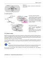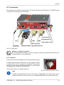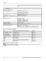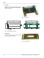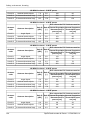
1
User manual . RipEX Radio modem & Router . version 1.12.1 12/3/2015 fw 1.5.x.x RACOM s.r.o. • Mirova 1283 • 592 31 Nove Mesto na Morave • Czech Republic Tel.: +420 565 659 511 • Fax: +420 565 659 512 • E-mail: [email protected] www.racom.eu Table of Contents Important Notice .................................................................................................................................. 7 Quick guide ......................................................................................................................................... 8 1. RipEX – Radio router .................................................................................................................... 10 1.1. Introduction ......................................................................................................................... 10 1.2. Key Features ...................................................................................................................... 10 1.3. Standards ........................................................................................................................... 12 2. RipEX in detail ............................................................................................................................... 14 2.1. Modes of operation ............................................................................................................. 14 2.2. Bridge mode ....................................................................................................................... 14 2.3. Router mode ....................................................................................................................... 19 2.4. Serial SCADA protocols ..................................................................................................... 24 2.5. Combination of IP and serial communication ..................................................................... 25 2.6. Diagnostics & network management .................................................................................. 26 2.7. Firmware update and upgrade ........................................................................................... 27 2.8. Software feature keys ......................................................................................................... 28 3. Network planning ........................................................................................................................... 29 3.1. Data throughput, response time ......................................................................................... 29 3.2. Frequency .......................................................................................................................... 30 3.3. Signal budget ..................................................................................................................... 31 3.4. Multipath propagation, DQ ................................................................................................. 33 3.5. Network layout .................................................................................................................... 35 3.6. Hybrid networks .................................................................................................................. 37 3.7. Assorted practical comments ............................................................................................. 37 3.8. Recommended values ........................................................................................................ 39 4. Product .......................................................................................................................................... 40 4.1. Dimensions ......................................................................................................................... 40 4.2. Connectors ......................................................................................................................... 43 4.3. Indication LEDs .................................................................................................................. 50 4.4. Technical specification ........................................................................................................ 51 4.5. Model offerings ................................................................................................................... 65 4.6. Accessories ........................................................................................................................ 68 5. Bench test ..................................................................................................................................... 75 5.1. Connecting the hardware ................................................................................................... 75 5.2. Powering up your RipEX .................................................................................................... 75 5.3. Connecting RipEX to a programming PC ........................................................................... 75 5.4. Basic setup ......................................................................................................................... 79 5.5. Functional test .................................................................................................................... 79 6. Installation ..................................................................................................................................... 80 6.1. Mounting ............................................................................................................................. 80 6.2. Antenna mounting .............................................................................................................. 83 6.3. Antenna feed line ............................................................................................................... 84 6.4. Grounding ........................................................................................................................... 84 6.5. Connectors ......................................................................................................................... 84 6.6. Power supply ...................................................................................................................... 84 7. Advanced Configuration ................................................................................................................ 86 7.1. Menu header ...................................................................................................................... 86 7.2. Status ................................................................................................................................. 87 7.3. Settings ............................................................................................................................... 88 7.4. Routing ............................................................................................................................. 133 7.5. Diagnostic ......................................................................................................................... 137 7.6. Maintenance ..................................................................................................................... 154 © RACOM s.r.o. – RipEX Radio modem & Router 3 RipEX Radio modem & Router 8. CLI Configuration ........................................................................................................................ 160 9. Troubleshooting ........................................................................................................................... 161 10. Safety, environment, licensing ................................................................................................... 163 10.1. Frequency ...................................................................................................................... 163 10.2. Safety distance ............................................................................................................... 163 10.3. High temperature ............................................................................................................ 167 10.4. RoHS and WEEE compliance ........................................................................................ 167 10.5. Hazardous locations ....................................................................................................... 168 10.6. Conditions of Liability for Defects and Instructions for Safe Operation of Equipment .... 169 10.7. Important Notifications .................................................................................................... 169 10.8. Product Conformity ......................................................................................................... 170 10.9. Compliance Federal Communications Commission ...................................................... 178 10.10. Country of Origin .......................................................................................................... 179 10.11. Warranty ....................................................................................................................... 180 A. OID mappings ............................................................................................................................. 181 B. Abbreviations .............................................................................................................................. 182 Index ................................................................................................................................................ 184 C. Revision History .......................................................................................................................... 187 List of Figures 1. RipEX radio router ........................................................................................................................... 8 2.1. Bridge mode example ................................................................................................................ 17 2.2. Addressing ................................................................................................................................. 22 2.3. Optimised addressing ................................................................................................................. 23 2.4. Monitoring ................................................................................................................................... 27 3.1. Application bench test ................................................................................................................ 30 3.2. Signal path ................................................................................................................................. 31 3.3. Multipath propagation ................................................................................................................. 33 3.4. Antenna location ......................................................................................................................... 34 3.5. Main lobe .................................................................................................................................... 35 3.6. Dominant repeater – straightforward layout ............................................................................... 36 3.7. Isolated branches – more robust layout ..................................................................................... 37 3.8. Antenna mounting ...................................................................................................................... 38 4.1. RipEX dimensions ...................................................................................................................... 40 4.2. RipEX dimensions – bottom ....................................................................................................... 41 4.3. RipEX with DIN rail ..................................................................................................................... 41 4.4. RipEX dimensions with connectors ............................................................................................ 42 4.5. Connectors ................................................................................................................................. 43 4.6. Antenna connector TNC ............................................................................................................. 43 4.7. Separated Rx and TX antennas ................................................................................................. 44 4.8. Supply connector ........................................................................................................................ 45 4.9. Power and Control - cable plug .................................................................................................. 45 4.10. RJ-45F ...................................................................................................................................... 46 4.11. Serial connector ........................................................................................................................ 47 4.12. Serial connector ....................................................................................................................... 47 4.13. Reset button ............................................................................................................................. 48 4.14. GPS Connector SMA ............................................................................................................... 49 4.15. Indication LEDs ........................................................................................................................ 50 4.16. RipEX-HS ................................................................................................................................. 68 4.17. RipeX-HS dimensions .............................................................................................................. 68 4.18. Adapter ETH/USB .................................................................................................................... 68 4 RipEX Radio modem & Router – © RACOM s.r.o. RipEX Radio modem & Router 4.19. WiFi dapter ............................................................................................................................... 69 4.20. Demo case ............................................................................................................................... 69 4.21. L-bracket .................................................................................................................................. 70 4.22. RipEX with L-bracket ................................................................................................................ 70 4.23. Flat bracket ............................................................................................................................... 70 4.24. RipEX with Flat-bracket ............................................................................................................ 71 4.25. Flat-bracket dimensions ........................................................................................................... 71 4.26. 19" Rack shelf .......................................................................................................................... 72 4.27. 19" Rack shelf – dimensions .................................................................................................... 72 4.28. 19" Rack shelf – double ........................................................................................................... 73 4.29. 19" Rack shelf–double – dimensions ....................................................................................... 73 4.30. Dummy load ............................................................................................................................. 74 5.1. Bench test .................................................................................................................................. 75 5.2. Connecting to a PC over ETH and over WiFi or ETH/USB adapter ........................................... 76 5.3. PC address setting ..................................................................................................................... 77 5.4. Authentication ............................................................................................................................. 78 5.5. Status Menu ............................................................................................................................... 78 6.1. Flat lengthwise mounting to DIN rail – recommended ............................................................... 80 6.2. Flat widthwise mounting to DIN rail ............................................................................................ 81 6.3. Clip mounting ............................................................................................................................. 81 6.4. Vertical widthwise mounting to DIN rail ...................................................................................... 81 6.5. Vertical lengthwise mounting to DIN rail ..................................................................................... 81 6.6. Flat mounting using Flat bracket ................................................................................................ 82 6.7. Vertical lengthwise mounting to DIN rail ..................................................................................... 82 6.8. Rack shelf ................................................................................................................................... 83 6.9. 10–30 VDC Supplying ................................................................................................................ 85 7.1. Menu Header .............................................................................................................................. 86 7.2. Menu Status ............................................................................................................................... 87 7.3. Menu Settings ............................................................................................................................ 88 7.4. Menu Alarm management .......................................................................................................... 99 7.5. Menu Radio .............................................................................................................................. 105 7.6. Menu Ethernet .......................................................................................................................... 109 7.7. Menu COM ............................................................................................................................... 117 7.8. Menu Protocols COM ............................................................................................................... 119 7.9. Menu Routing ........................................................................................................................... 133 7.10. Menu Neighbours ................................................................................................................... 137 7.11. Menu Statistic ......................................................................................................................... 140 7.12. Menu Graphs .......................................................................................................................... 141 7.13. Menu Ping .............................................................................................................................. 143 7.14. Menu Monitoring ..................................................................................................................... 146 7.15. Monitoring ............................................................................................................................... 151 7.16. Menu SW feature keys ........................................................................................................... 154 7.17. Menu Maintenance Configuration .......................................................................................... 155 7.18. Menu Maintenance Firmware ................................................................................................. 155 7.19. Menu Maintenance Password ................................................................................................ 157 7.20. Menu Maintenance Configuration .......................................................................................... 159 10.1. Declaration of Conformity RipEX ........................................................................................... 171 10.2. ATEX Certificate RipEX .......................................................................................................... 172 10.3. IECEx Certificate RipEX ......................................................................................................... 175 10.4. Country of Origin declaration for RipEX ................................................................................. 179 List of Tables © RACOM s.r.o. – RipEX Radio modem & Router 5 RipEX Radio modem & Router 4.1. Pin assignement ......................................................................................................................... 44 4.2. Ethernet to cable connector connections ................................................................................... 46 4.3. COM1, 2 pin description ............................................................................................................. 47 4.4. USB pin description .................................................................................................................... 47 4.5. Key to LEDs ............................................................................................................................... 50 4.6. Technical parameters ................................................................................................................. 51 4.7. Recommended Cables ............................................................................................................... 54 4.8. Unlimited 50 kHz ........................................................................................................................ 55 4.9. CE 50 kHz .................................................................................................................................. 56 4.10. CE 25 kHz ................................................................................................................................ 57 4.11. CE 12.5 kHz ............................................................................................................................. 58 4.12. CE 6.25 kHz ............................................................................................................................. 59 4.13. FCC 50 kHz .............................................................................................................................. 60 4.14. FCC 25 kHz .............................................................................................................................. 60 4.15. FCC 25 kHz RipEX-928, RipEX-215 ........................................................................................ 61 4.16. FCC 12.5 kHz ........................................................................................................................... 62 4.17. FCC 6.25 kHz ........................................................................................................................... 62 4.18. Narrow 25 kHz .......................................................................................................................... 63 10.1. Minimum Safety Distance 160 MHz ....................................................................................... 163 10.2. Minimum Safety Distance 216–220 MHz ............................................................................... 165 10.3. Minimum Safety Distance 300–400 MHz ............................................................................... 165 10.4. Minimum Safety Distance 928–960 MHz ............................................................................... 167 10.5. Maximum voltage and current of individual interfaces ........................................................... 168 10.6. Compliance Federal Communications Commission .............................................................. 178 6 RipEX Radio modem & Router – © RACOM s.r.o. Important Notice Important Notice Copyright © 2013 RACOM. All rights reserved. Products offered may contain software proprietary to RACOM s. r. o. (further referred to under the abbreviated name RACOM). The offer of supply of these products and services does not include or infer any transfer of ownership. No part of the documentation or information supplied may be divulged to any third party without the express written consent of RACOM. Disclaimer Although every precaution has been taken in preparing this information, RACOM assumes no liability for errors and omissions, or any damages resulting from the use of this information. This document or the equipment may be modified without notice, in the interests of improving the product. Trademark All trademarks and product names are the property of their respective owners. Important Notice • • • • Due to the nature of wireless communications, transmission and reception of data can never be guaranteed. Data may be delayed, corrupted (i.e., have errors), or be totally lost. Significant delays or losses of data are rare when wireless devices such as the RipEX are used in an appropriate manner within a well‐constructed network. RipEX should not be used in situations where failure to transmit or receive data could result in damage of any kind to the user or any other party, including but not limited to personal injury, death, or loss of property. RACOM accepts no liability for damages of any kind resulting from delays or errors in data transmitted or received using RipEX, or for the failure of RipEX to transmit or receive such data. Under no circumstances is RACOM or any other company or person responsible for incidental, accidental or related damage arising as a result of the use of this product. RACOM does not provide the user with any form of guarantee containing assurance of the suitability and applicability for its application. RACOM products are not developed, designed or tested for use in applications which may directly affect health and/or life functions of humans or animals, nor to be a component of similarly important systems, and RACOM does not provide any guarantee when company products are used in such applications. The equipment should be used in hazardous locations under conditions according to Section 10.5, “Hazardous locations” only. © RACOM s.r.o. – RipEX Radio modem & Router 7 Quick guide Quick guide RipEX is a widely configurable compact radio modem, more precisely a radio IP router. All you have to do to put it into operation is to connect it to an antenna and a power supply and configure it using a PC (tablet, smart phone) and a web browser. Antenna Sleep Input HW Alarm Input - GND + HW Alarm Output Supply +10 to +30 V - GND Indicator LEDs' ANT SI AI - + AO + - 10 – 30VDC ETH Default/Reset USB Ethernet COM 1 USB COM 2 COM1 RS232 COM2 RS232/485 Fig. 1: RipEX radio router RipEX access defaults: username: admin, password: admin Ethernet RipEX default IP is 192.168.169.169/24, so set a static IP 192.168.169.x/24 on your PC, power on the RipEX and wait approximately 48 seconds for the RipEX OS to boot. Connect your PC to RipEXs' ETH interface, start your browser and type https://192.168.169.169 in the address line. Before attempting to do any configuration, make sure your RipEX is the only powered-up unit around. Since all units coming from factory share the same default settings ex factory, you could be accessing a different unit over the air without being aware of it. USB/ETH adapter When accessing over the optional “X5” USB/ETH adapter, your PC will get its IP settings from the builtin DHCP server and you have to type https://10.9.8.7 in your browser. You do not need to worry about other RipEX'es, you will be connected to the local unit in all cases. Wifi adapter When accessing over the optional “W1” Wifi adapter, connect your PC (tablet, smart phone) to the RipEX Wifi AP first. Its default SSID is “RipEX + Unit name + S/N” Your PC will get its IP settings from the built-in DHCP server and you have to type http://10.9.8.7 in your browser. Remaining steps are the same and you do not need to worry about other RipEX'es, since you will be connected to the local unit in all cases. 8 RipEX Radio modem & Router – © RACOM s.r.o. Quick guide SCADA radio network step-by-step Building a reliable radio network for a SCADA system may not be that simple, even when you use such a versatile and easy-to-operate device as the RipEX radio modem. The following step-by-step checklist can help you to keep this process fast and efficient. 1. 2. 3. 4. 5. 6. 7. 1 Design your network to ensure RF signal levels meet system requirements. Calculate and estimate the network throughput and response times when loaded by your application. Perform a bench-test with 3-5 sets of RipEX's and SCADA equipment (Chapter 5, Bench test). Design the addressing and routing scheme of the network (Chapter 2, RipEX in detail and RipEX 1 App notes, Address planing ) Preconfigure all RipEX's (Section 5.4, “Basic setup”). Install individual sites 1. Mount RipEX into cabinet (Section 6.1, “Mounting”). 2. Install antenna (Section 6.2, “Antenna mounting”). 3. Install feed line (Section 6.3, “Antenna feed line”). 4. Ensure proper grounding (Section 6.4, “Grounding”). 5. Run cables and plug-in all connectors except from the SCADA equipment (Section 4.2, “Connectors”) 6. Apply power supply to RipEX 7. Test radio link quality (Section 5.5, “Functional test”). 8. Check routing by the ping tool (the section called “Ping”) to verify accessibility of all IP addresses with which the unit will communicate. 9. Connect the SCADA equipment Test your application http://www.racom.eu/eng/products/m/ripex/app/routing.html © RACOM s.r.o. – RipEX Radio modem & Router 9 RipEX – Radio router 1. RipEX – Radio router 1.1. Introduction RipEX is a best-in-class radio modem, not only in terms of data transfer speed. This Software Defined Radio with Linux OS has been designed with attention to detail, performance and quality. All relevant state-of-the-art concepts have been carefully implemented. RipEX provides 24×7 reliable service for mission-critical applications like SCADA & Telemetry for Utilities, SmartGrid power networks or transaction networks connecting lottery terminals, POS or ATM’s. Any unit can serve as the central master, repeater, remote terminal, or all of these simultaneously, with a configuration interface easily accessible from a web browser. Anybody with even basic knowledge of IP networking can set up a RipEX within a matter of minutes and maintain the network quite easily. 1.2. Key Features • Exceptional data speeds on the radio channel - 166 kbps / 50 kHz, 83 kbps / 25 kHz, 42 kbps / 12.5 kHz, 21 kbps / 6.25 kHz • 1× ETH, 2× COM, 1× USB, 5× virtual COM - Simultaneously on radio channel. COM1-RS232, COM2-RS232 or RS485, software configurable. Virtual COMs over ETH controlled by Terminal servers. USB for independent service access via USB/ETH adapter and for automatic FW and SW keys upgrade. • Wifi management - Any smart phone, tablet or notebook can be used as a RipEX portable display. • 135–174; 215–240; 300–360; 368–512; 928–960 MHz - Licensed radio bands - Software-selectable channel spacing 50, 25, 12.5 or 6.25 kHz • 10 watts - Transmission output control, nine stages from 0.1 to 10 W. Hence linear modulations (the highest data speed) require a very linear RF power amplifier, max. 2 W is available for them. • Energy saving - Sleep mode – 0.1 W, controlled via a digital input. - Save mode – 2 W, wake up by receiving a packet from the Radio channel • Extended temperature range −40 to +70 ºC • Easy to configure and maintain - Web interface, - Wizards, - On-line help, - Balloon tips, - Fastest web access to remote units 10 RipEX Radio modem & Router – © RACOM s.r.o. RipEX – Radio router • Fast remote access - Only the effective data are transferred from remote RipEX over the air, html page is downloaded from the local unit. • Bridge or Router - RipEX is a device with native IP support which can be set as a standard bridge or router. • Modbus, IEC101, DNP3, Siemens 3964(R), Comli, RP570, C24, DF1, Profibus, SLIP, Modbus TCP, IEC104, DNP3 TCP etc. - Unique implementation of industrial protocols enables a secure addressed transmission of all packets in all directions • Anti-collision protocol on radio channel - Allows multi polling & report-by-exception concurrently for several independent applications simultaneously • Backup routes - When tested path between two RipEX IP addresses (even behind repeater or LAN) fails, automatic switch-over to backup gateway behind Radio or Ethernet interfaces - Unlimited number of prioritized backup gateways - Instructional video http://www.racom.eu/ripex-backup • Optimization – 3× higher throughput - Optimization method which joins short packets, compresses data, optimises both the traffic to the link peer and the sharing of the radio channel capacity among the links. • TCP proxy - Eliminates a transfer of TCP overhead over Radio channel when TCP overhead run locally between connected device and RipEX on LAN. I.e. only payload (user) data are transferred further as UDP (over Radio channel) - Higher RipEX network bandwidth, no more problems with TCP timeouts - Instructional video http://www.racom.eu/ripex-tcp-proxy • ARP proxy - RipEX can simulate any IP address (it may reply to any ARP request) - This feature is typically used when RTU’s addresses behind different RipEX units are within the same IP subnet and RTU’s do not provide routing capabilities (neither default GW) - Instructional video http://www.racom.eu/ripex-arp-proxy • VLAN & Subnets - RipEX can simulate any IP address (it may reply to any ARP request) - Unlimited number of virtual Ethernet interfaces (IP aliases) can be set • Embedded diagnostic & NMS - Real time and historical (20 periods, e.g. days) statistics and graphs for the unit and its neighbours. - SNMP including generation of TRAP alarms when preset thresholds are exceeded - on-line/off-line (recorded to a file in the RipEX) monitoring of all interfaces • Security - 256 AES encryption, the most secure encryption meets FIPS 140 2 requirements - 2048 (1024, 512) bit SSL certificate (even your own one) for https web configuration • SW feature keys © RACOM s.r.o. – RipEX Radio modem & Router 11 RipEX – Radio router Software authorization keys allow you to add advanced features when needed: Router mode, 166/83 (The two highest Data rates for 25 and 50 kHz channel spacing), COM2, 10 W, Backup routes - Free Master-key trial – (all coded features) for 30 days in every RipEX • Reliability - 3 years warranty, rugged die cast aluminium case, military or industrial components - Every single unit tested in a climatic chamber as well as in real traffic • RipEX - HS - Redundant hot standby chassis - Two hot-stand-by standard RipEX units inside - Automatic switchover capability on detection of failure - Suitable for Central sites, Repeaters or Important remote sites where no single point of failure is required • Internal calendar time - Can be set manually or synchronized via NTP (Network Time Protocol) - Any RipEX also runs as a NTP server automatically - NTP synchronization via Ethernet or over the Radio channel from another RipEX or from the builtin GPS - Powered from internal long life Lithium Manganese battery, so it is accurate even when RipEX is powered off • Flash memory - All configuration parameters are saved in flash memory - Configuration and other parameters are safely saved even when RipEX is powered off • External Flash disc - Automatic firmware upgrade, SW keys upload, configuration backup/restore, ssl certificate and ssh keys upload and configuration, tech-support package download - Configuration and other parameters are safely saved even when RipEX is powered off 1.3. Standards Radio ETSI EN 300 113-2 V1.5.1 FCC Part 90, FCC Part 101 EMC ETSI EN 301 489-1 V1.9.2 ETSI EN 301 489-5 V1.3.1 IEEE 1613:2009 Class 1 Electrical Safety EN 60950-1:2006 EN 60950–1:2006/A11:2009, EN 60950–1:2006/A12:2011, EN 60950–1:2006/A1:2010 Vibration & shock EN 61373:1999 Seismic qualification IEC 980:1989 (seismic category 1a) 12 RipEX Radio modem & Router – © RACOM s.r.o. RipEX – Radio router Explosive atmospheres EN 60079-0:2012, IEC60079-0:2011, UL60079-0:2013 EN 60079-11:2012, IEC60079-11:2011, UL60079-11:2013 IP rating IP40 ETH IEEE 802.3i IEEE 802.3u IEEE 802.3af RS232 EIA-232-F RS485 EIA RS-485 IEC101 IEC 60870-5-101 IEC104 IEC 60870-5-104 DNP3 IEEE 1815-2010 Profibus DP IEC 61158 Type 3 SLIP RFC 1055 VLAN IEEE 802.1Q Wifi IEEE 802.11g,n © RACOM s.r.o. – RipEX Radio modem & Router 13 RipEX in detail 2. RipEX in detail 2.1. Modes of operation Radio modem RipEX is best suited for transmission of a large number of short messages where a guaranteed delivery time is required, i.e. for mission critical applications. RipEX has the following basic uses: • Polling In poll-response networks a central master unit communicates with a number of remote radiomodems one at a time. The master unit exchanges data with the currently connected remote radio, and when finished, it establishes a new connection with the next remote radio according to the polling order. • Report-by-exception In report-by-exception networks remote units can be contacted similarly to polling networks. In addition, any remote unit can spontaneously send data to the master unit (typically an alarm). • Mesh In mesh type networks any radio modem in the network can access any other radio modem randomly and spontaneously. Mesh network can also host polling or report-by-exception applications, even in several instances. 2.2. Bridge mode A packet received through any interface is broadcast to the appropriate interfaces of all units within the network. Packets received on COM are broadcast to both COM1 and COM2 at remote sites, allowing you to connect 2 RTU's to any radio modem. Any unit can be configured as a repeater. A repeater relays all packets it receives through the radio channel. The network implements safety mechanisms which prevent cyclic loops in the radio channel (e.g. when a repeater receives a packet from another repeater) or duplicate packets delivered to the user interface (e.g. when RipEX receives a packet directly and then from a repeater). Beside standard packet termination by an "Idle" period on the serial port (a pause between received bytes) the bridge mode also offers "streaming". While in streaming mode, transmission on the radio channel starts immediately, without waiting for the end of the received frame on COM => zero latency. The bridge mode is suitable for all polling applications. Note Limited broadcast 255.255.255.255 and Direct broadcast e.g. 192.168.255.255 as well as Multicast (224.0.0.0 through 239.255.255.255) on Ethernet are supported and transferred over the network. You can see an instructional video explaining the Bridge mode functionality here: http://www.racom.eu/ripex-bridge-mode 14 RipEX Radio modem & Router – © RACOM s.r.o. RipEX in detail 2.2.1. Detailed Description Bridge mode is suitable for Point-to-Multipoint networks, where Master-Slave applications with pollingtype communication protocol are used. RipEX in bridge mode is as easy to use as a simple transparent device, while providing communication reliability and spectrum efficiency by employing a sophisticated protocol in the radio channel. In bridge mode, the radio channel protocol do not solve collisions. There is a CRC check of data integrity, however, i.e. once a message is delivered, it is 100% error free. All the messages received from user interfaces (ETH&COM's) are immediately transmitted to the radio channel. ETH - The whole network of RipEX radiomodems behaves as a standard ethernet network bridge. Each ETH interface automatically learns which devices (MAC addresses) are located in the local LAN and which devices are accessible over the radio channel. Consequently, only the ethernet frames addressed to remote devices are physically transmitted on the radio channel. This arrangement saves the precious RF spectrum from extra load which would be otherwise generated by local traffic in the LAN (the LAN to which the respective ETH interface is connected). One has to be very careful when RipEX in Bridge mode is connected to LAN, because all LAN traffic is then broadcast to the Radio channel. COM1,COM2 - All frames received from COM1(2) are broadcast over the radio channel and transmitted to all COM's (COM1 as well as COM2) on all radio modems within the network, the other COM on the source RipEX excluding. There is a special parameter TX delay (Adv. Config., Device), which should be used when all substations (RTU's) reply to a broadcast query from the master station. In such case massive collisions would ensue because all substations (RTU's) would reply at nearly the same time. To prevent such collision, TX delay should be set individually in each slave RipEX. The length of responding frame, the length of radio protocol overhead, modulation rate have to be taken into account. 2.2.2. Functionality example In the following, common acronyms from SCADA systems are used: • • FEP - Front End Processor, designates the communication interface equipment in the centre RTU - Remote Telemetry Unit, the terminal SCADA equipment at remote sites The single digits in illustrations are “site names” and do not necessarily correspond with actual addresses of both the RipEX's and SCADA equipment. Address configuration examples are given in the next chapter. Step 1 Polling cycle starts: FEP sends a request packet for RTU3 through COM1 to the connected RipEX. © RACOM s.r.o. – RipEX Radio modem & Router 15 RipEX in detail Step 2 FEP’s RipEX broadcasts this packet on Radio channel. RipEX3 and RipEX1 receive this packet. RipEX2 doesn’t receive this packet, because it is not within radio coverage of FEP’s RipEX. Step 3 RipEX3 and RipEX1 send the received packet to their COM1 and COM2. Packet is addressed to RTU3, so only RTU3 responds. RipEX1 is set as a repeater, so it retransmits the packet on Radio channel. Packet is received by all RipEXes. Step 4 RipEX2 sends repeated packet to its COM1 and COM2. RTU2 doesn’t react, because the packet is addressed to RTU3. RipEX3 and FEP’s RipEX do not send the repeated packet to their COM ports, because it has already been sent (RipEX3) or received (FEP’s RipEX) on their COM (anti-duplication mechanism). RTU3 sends the reply packet. Step 5 RipEX3 broadcasts the reply packet from RTU3 on Radio channel. Packet is received by RipEX1 and FEP’s RipEX. Step 6 FEP’s RipEX sends the packet (the reply from RTU3) to FEP through COM1. RipEX1 sends this packet to RTU1. RTU1 doesn’t react, because the packet is addressed to FEP. RipEX1 repeats the packet on Radio channel. All RipEXes receive the packet. 16 RipEX Radio modem & Router – © RACOM s.r.o. RipEX in detail Step 7 RipEX2 sends repeated packet to its COM1 and COM2. RTU2 doesn’t react, because the packet is addressed to FEP. RipEX3 and FEP’s RipEXes do not send the repeated packet to their COM ports, because it has been handled already. FEP processes the reply from RTU3 and polling cycle continues… 2.2.3. Configuration examples You can see an example of IP addresses of the SCADA equipment and RipEX's ETH interfaces in the picture below. In Bridge mode, the IP address of the ETH interface of RipEX is not relevant for user data communication. However it is strongly recommended to assign a unique IP address to each RipEXs' ETH interface, since it allows for easy local as well as remote service access. Moreover, leaving all RipEX's with the same (= default) IP on the ETH interface may cause serious problems, when more RipEX's are connected to the same LAN, even if by accident (e.g. during maintenance). 192.168.5.13/24 3 192.168.5.3/24 192.168.5.12/24 2 192.168.5.2/24 192.168.5.51/24 192.168.5.50/24 50 REPEATER FEP 192.168.5.11/24 1 192.168.5.1/24 Fig. 2.1: Bridge mode example © RACOM s.r.o. – RipEX Radio modem & Router 17 RipEX in detail Repeater Because using the bridge mode makes the network transparent, the use of repeaters has certain limitations. To keep matters simple we recommend using a single repeater. However, if certain rules are observed, using multiple repeaters in the same network is possible. The total number of repeaters in the network is configured for every unit individually under Bridge mode parameters. This information is contained in every packet sent. All units that receive such packet will resume transmission only after sufficient time has been allowed for the packet to be repeated. The packets received from user ports remain buffered and are sent after the appropriate time passes. This prevents collisions between remote radio modems. There can be no repeater collisions if only one repeater is used. Where two or more repeaters are used, collisions resulting from simultaneous reception of a repeated packet must be eliminated. Collisions happen because repeaters repeat packets immediately after reception, i.e. if two repeaters receive a packet from the centre, they both relay it at the same time. If there is a radiomodem which is within the range of both repeaters, it receives both repeated packets at the same time rendering them unreadable. Examples: 1. Repeaters connected serially 1 Centre 2 A packet is transmitted and repeated in steps 1, 2, 3. 3 RPT1 RPT2 Remote WRONG COLLISION! 2 X 1 2 1 CEN RPT1 RPT2 REM GOOD 1 CEN RPT1 2 3 RPT2 REM In improperly designed networks collisions happen if a remote radio modem lies in the range of two repeaters (see the image): the packet sent from the centre (1) is received by both repeaters. It is repeated by them both (2) causing a collision at the remote. In other words – there should not be more than one repeater where the centre and remotes' coverage areas overlap. Solution 1. Adjust signal coverage so that RPT2 is out of range of the centre and RPT1 is out of the range of the remote radio modem. This can be achieved for example by reducing the output power or using a unidirectional antenna. Coverage area 18 RipEX Radio modem & Router – © RACOM s.r.o. RipEX in detail Solution 2. Use a single repeater. (Whenever network layout allows that.) Good 2 1 CEN RPT1 REM 2. Parallel repeaters 1 2 Remote2 Improperly designed network: WRONG Repeater2 REM2 2 1 CEN RPT2 1 Centre 2 1 RPT1 2 2 REM1 X Repeater1 - RipEX REM1 is within the range of two repeaters (RPT1 and RPT2). The repeaters receive a packet (1) from the centre (CEN) and repeat it at the same time (2) causing a collision at REM1. COLLISION! Remote1 2 1 GOOD REM2 CEN 1 RPT1 Well-designed network: RPT2 2 REM1 - A remote is only in the range of a single repeater (REM1-RPT1, REM2-RPT2). There is always only one repeater where the centre and remote coverage areas overlap. 2.3. Router mode RipEX works as a standard IP router with two interfaces (radio and ethernet) and two COM port devices. There is a sophisticated anti-collision protocol on the radio channel, which checks and verifies every single packet. Being an IP router, each unit can simultaneously work as a store-and-forward repeater and deliver packets to the connected equipment. The router mode is suitable for all uses. In contrast to the bridge mode, a packet reception is confirmed over the radio channel even in very simple polling type applications, and if necessary the packet is retransmitted. Note Broadcasts (Limited or Direct) and Multicasts on Ethernet are not supported in Router mode. Only broadcasts in serial SCADA protocols are transferred according their settings. You can see an instructional video explaining the Router mode functionality here: http://www.racom.eu/ripex-router-mode © RACOM s.r.o. – RipEX Radio modem & Router 19 RipEX in detail 2.3.1. Detailed Description Router mode is suitable for multipoint networks, where multi-master applications with any combination of polling and/or spontaneous data protocols can be used. The proprietary link-layer protocol on the radio channel is very sophisticated, it can transmit both unicast and broadcast frames, it has collision avoidance capability, it uses frame acknowledgement, retransmissions and CRC checks to guarantee data delivery and integrity even under harsh interference conditions on the radio channel. RipEX works as a standard IP router with 2 independent interfaces: radio and ETH. Each interface has its own MAC address, IP address and mask. IP packets are processed according the routing table rules. You can also set the router’s default gateway (applies to both interfaces) in the routing table. The COM ports are treated as standard host devices, messages can be delivered to them as UDP datagrams to selected port numbers. The destination IP address of a COM port is either the IP of ETH or the IP of a radio interface. The source IP address of outgoing packets from COM ports is always the IP of the ETH interface. 2.3.2. Functionality example In the following example, there are two independent SCADA devices connected to RipEX's two COM ports. One is designated RTU (Remote Telemetry Unit) and is assumed to be polled from the centre by the FEP (Front End Processor). The other is labelled PLC (Programmable Logic Controller) and is assumed to communicate spontaneously with arbitrary chosen peer PLCs. Step 1 FEP sends a request packet for RTU1 through COM2 to its connected RipEX. Simultaneously PLC2 sends a packet for PLC1 to RipEX2 through COM1. Step 2 FEP’s RipEX transmits an addressed packet for RTU1 on Radio channel. RipEX1 receives this packet, checks data integrity and transmits the acknowledgement. At the same time packet is sent to RTU1 through COM2. RipEX3 receives this packet too. It doesn’t react, because this packet is directed to RipEX1 only. 20 RipEX Radio modem & Router – © RACOM s.r.o. RipEX in detail Step 3 RipEX2 waits till previous transaction on Radio channel is finished (anti-collision mechanism). Then RipEX2 transmits on Radio channel the addressed packet for PLC1. RipEX1 receives this packet, checks data integrity and transmits acknowledgement. At the same time packet is sent to PLC1 through COM1. Simultaneously the reply packet from RTU1 for FEP is received on COM2. Step 4 RipEX1 transmitts the reply packet from RTU1 for FEP on Radio channel. All RipEXes receive this packet. This packet is addressed to FEP’s RipEX, so only FEP’s RipEX reacts. It checks data integrity and transmits the acknowledgement to RipEX1. At the same time the packet is sent to FEP through COM2. Step 5 FEP receives the response from RTU1 and polling cycle continues… However any PLC or RTU can spontaneously send a packet to any destination anytime. 2.3.3. Configuration examples As it was mentioned above, RipEX radiomodem works as a standard IP router with two independent interfaces: radio and ETH. Each interface has got its own MAC address, IP address and mask. The IP router operating principles stipulate that every unit can serve as a repeater.. Everything what is needed is the proper configuration of routing tables. Radio IP addresses of the RipEX’s required to communicate over the radio channel must share the same IP network. We recommend planning your IP network so that every RipEX is connected to a separate sub-network over the ethernet port. This helps to keep the routing tables clear and simple. Note Even if the IP addresses of all RipEXes in a radio channel share a single IP network, they may not be communicating directly as in a common IP network. Only the RipEXes that are within the radio range of each other can communicate directly. When communication with radio IP addresses is required, routing tables must include even the routes that are within the same network (over repeaters), which is different from common IP networks. The example configuration below does not show such routing rules for the sake of simplicity (they are not needed in most cases). © RACOM s.r.o. – RipEX Radio modem & Router 21 RipEX in detail 10.10.10.3/24 Routing table RipEX3: 192.168.50.0/24 è 10.10.10.50 192.168.1.0/24 è 10.10.10.50 192.168.2.0/24 è 10.10.10.50 192.168.3.1/24 3 192.168.3.2/24 Radio IP 10.10.10.50/24 Routing table RipEX2: 192.168.1.0/24 è 10.10.10.1 192.168.50.0/24 è 10.10.10.1 192.168.3.0/24 è 10.10.10.1 10.10.10.2/24 Routing table RipEX50: 192.168.1.0/24 è 10.10.10.1 192.168.2.0/24 è 10.10.10.1 192.168.3.0/24 è 10.10.10.3 Default GW 192.168.50.2 192.168.2.1/24 2 192.168.2.2/24 ETH IP 192.168.50.1/24 FEP IP 192.168.50.2/24 50 Routing table RipEX1: 192.168.2.0/24 è 10.10.10.2 192.168.50.0/24 è 10.10.10.50 192.168.3.0/24 è 10.10.10.50 10.10.10.1/24 FEP 192.168.1.1/24 1 192.168.1.2/24 Fig. 2.2: Addressing Formal consistency between the last byte of the radio IP address and the penultimate byte of the ethernet address is not necessary but simplifies orientation. The “Addressing” image shows a routing table next to every RipEX. The routing table defines the next gateway for each IP destination. In radio transmission, the radio IP of the next radio-connected RipEX serves as the gateway. Example of a route from FEP (RipEX 50) to RTU 2: • • • • • • • • 22 The destination address is 192.168.2.2 The routing table of the RipEX 50 contains this record: Destination 192.168.2.0/24 Gateway 10.10.10.1 Based on this record, all packets with addresses in the range from 192.168.2.1 to 192.168.2.254 are routed to 10.10.10.1 Because RipEX 50’s radio IP is 10.10.10.50/24, the router can tell that the IP 10.10.10.1 belongs to the radio channel and sends the packet to that address over the radio channel The packet is received by RipEX 1 with the address 10.10.10.1 where it enters the router The routing table of RipEX 1 contains the record: Destination 192.168.2.0/24 Gateway 10.10.10.2 based on which the packet is routed to 10.10.10.2 over the radio channel The packet is received by RipEX 2 The router compares the destination IP 192.168.2.2 with its own ethernet address 192.168.2.1/24 and determines that the packet’s destination is within its ETH network and sends the packet over the ethernet interface – eventually, the packet is received by RTU 2. RipEX Radio modem & Router – © RACOM s.r.o. RipEX in detail 2.3.4. Addressing hints In large and complex networks with numerous repeaters, individual routing tables may become long and difficult to comprehend. To keep the routing tables simple, the addressing scheme should follow the layout of the radio network. More specifically, every group of IP addresses of devices (both RipEX's and SCADA), which is accessed via a repeater, should fall in a range which can be defined by a mask and no address defined by that mask exists in different part of the network. A typical network consisting of a single centre and number of remotes has got a tree-like layout, which can be easily followed by the addressing scheme – see the example in the Figure Optimised addressing below. Routing table RipEX4: 192.168.0.0/16 è 10.10.10.50 10.10.10.4/24 192.168.4.1/24 Routing table RipEX2: 192.168.0.0/16 è 10.10.10.1 4 192.168.4.2/24 Radio IP 10.10.10.50/24 10.10.10.2/24 Routing table RipEX50: 192.168.0.0/22 è 10.10.10.1 192.168.4.0/22 è 10.10.10.4 Default GW 192.168.50.2 192.168.2.1/24 2 192.168.2.2/24 ETH IP 192.168.50.1/24 FEP IP 192.168.50.2/24 50 10.10.10.1/24 Routing table RipEX1: 192.168.2.0/24 è 10.10.10.2 192.168.0.0/16 è 10.10.10.50 FEP 192.168.1.1/24 1 192.168.1.2/24 Fig. 2.3: Optimised addressing The default gateway is also a very powerful routing tool, however be very careful whenever the default route would go to the radio interface, i.e. to the radio channel. If a packet to non-existing IP destination came to the router, it would be transmitted over the radio channel. Such packets increase the load of the network at least, cause excessive collisions, may end-up looping etc. Consequently the default route should always lead to the ETH interface, unless you are perfectly certain that a packet to nonexisting destination IP may never appear (remember you are dealing with complex software written and configured by humans). © RACOM s.r.o. – RipEX Radio modem & Router 23 RipEX in detail 2.4. Serial SCADA protocols Even when the SCADA devices are connected via serial port, communication remains secured and address-based in all directions (centre-RTU, RTU-centre, RTU-RTU). In router mode, RipEX utilises a unique implementation of various SCADA protocols (Modbus, IEC101, DNP3, Comli, RP570, C24, DF1, Profibus). In this implementation SCADA protocol addresses are mapped to RipEX addresses and individual packets are transmitted as acknowledged unicasts. Polled remote units respond to the unit that contacted them (multi master network possible) using secure packets. When needed, RTU-RTU parallel communication is also possible. 2.4.1. Detailed Description Each SCADA protocol, such as Modbus, DNP3, IEC101, DF1, etc., has its own unique message format, and more importantly, its unique way of addressing remote units. The basic task for protocol utility is to check whether a received frame is in the correct protocol format and uncorrupted. Most of the SCADA protocols use some type of error detection codes (Checksum, CRC, LRC, BCC, etc.) for data integrity control, so RipEX calculates this code and check it with the received one. RipEX radio network works in IP environment, so the basic task for the protocol interface utility is to convert SCADA serial packets to UDP datagrams. Address translation settings are used to define the destination IP address and UDP port. Then these UDP datagrams are sent to RipEX router, processed and typically forwarded as unicasts over the radio channel to their destination. If the gateway defined in the routing table belongs to the ethernet LAN, UDP datagrams are rather forwarded to the ethernet interface. After reaching the gateway (typically a RipEX router), the datagram is again forwarded according to the routing table. Above that, RipEX is can to handle even broadcast packets from serial SCADA protocols. When broadcasts are enabled in the respective Protocol settings, the defined packets are treated as broadcast (e.g. they are not acknowledged on Radio channel). On the Repeater station, it is possible to set whether broadcast packets shall be repeated or not. Note 1. 2. Broadcast packets are supported only on serial interfaces. Neither broadcast nor multicast are supported on Ethernet when in Router mode. UDP datagrams can be acknowledged on the radio channel (ACK parameter of router mode) but they are not acknowledged on the ethernet channel. When a UDP datagram reaches its final IP destination, it should be in a RipEX router again (either its ETH or radio interface). It is processed further according its UDP port. Either it is delivered to COM1(2) port daemon, where the datagram is decapsulated and the data received on serial interface of the source unit is forwarded to COM1(2), or the UDP port is that of a Terminal server or any other special protocol daemon on Ethernet like Modbus TCP etc. Then the datagram is processed by that daemon accordingly to the respective settings. RipEX uses a unique, sophisticated protocol on the radio channel. It guaranties data integrity even under heavy interference or weak signal conditions due to the 32 bit CRC used, minimises the likelihood of a collision and retransmits frames when collision happens, etc. These features allow for the most efficient SCADA application arrangements to be used, e.g. multi-master polling and/or spontaneous communication from remote units and/or parallel communication between remote units, etc. 24 RipEX Radio modem & Router – © RACOM s.r.o. RipEX in detail Important The anti-collision protocol feature is available only in the router mode. The bridge mode is suitable for simple Master-Slave arrangements with polling-type application protocol. 2.5. Combination of IP and serial communication RipEX enables combination of IP and serial protocols within a single application. Five independent terminal servers are available in RipEX. A terminal server is a virtual substitute for devices used as serial-to-TCP(UDP) converters. It encapsulates serial protocol to TCP(UDP) and vice versa eliminating the transfer of TCP overhead over the radio channel. If the data structure of a packet is identical for IP and serial protocols, the terminal server can serve as a converter between TCP(UDP)/IP and serial protocols (RS232, RS485). RipEX also provides a built-in converter Modus RTU – Modus TCP, where data structure is not the same, so one application may combine both protocols, Modus RTU and Modus TCP. You can see an instructional video explaining the Terminal server functionality here: http://www.racom.eu/ripex-terminal 2.5.1. Detailed Description Generally, a terminal server (also referred to as serial server) enables connection of devices with a serial interface to a RipEX over the local area network (LAN). It is a virtual substitute for the devices used as serial-to-TCP(UDP) converters. Examples of the use: A SCADA application in the centre should be connected to the radio network via serial interface, however, for some reason that serial interface is not used. The operating system (e.g. Windows) can provide a virtual serial interface to such application and converts the serial data to TCP (UDP) datagrams, which are then received by the terminal server in RipEX. This type of connection between RipEX and application provides best results when: • • • There is no hardware serial interface on the computer Serial cable between RipEX and computer would be too long. E.g. the RipEX is installed very close to the antenna to reduce feed line loss. LAN already exists between the computer and the point of installation Important The TCP (UDP) session operates only locally between RipEX and the central computer, hence it does not increase the load on the radio channel. In special cases, the terminal server can reduce network load from TCP applications . A TCP session can be terminated locally at the terminal server in RipEX, user data extracted from the TCP messages and processed as if it came from a COM port. When the data reaches the destination RipEX, it can be transferred to the RTU either via the serial interface or via TCP (UDP), using the terminal server again. Please note, that RipEX Terminal server implementation also supports the dynamical IP port change in every incoming application datagram. In such case the RipEX sends the reply to the port from which the last response has been received. This feature allows to extend the number of simultaneously © RACOM s.r.o. – RipEX Radio modem & Router 25 RipEX in detail opened TCP connections between the RipEX and the locally connected application up to 10 on each Terminal server. 2.6. Diagnostics & network management RipEX radiomodem offers a wide range of built-in diagnostics and network management tools. 2.6.1. Logs There are ‘Neighbours’ and Statistic logs in RipEX. For both logs there is a history of 20 log files available, so the total history of saved values is 20 days (assuming the default value of 1440 min. is used as the Log save period). Neighbours The ‘Neighbours’ log provides information about neighbouring units (RipEX’s which can be accessed directly over the radio channel, i.e. without a repeater). Every RipEX on the network regularly broadcasts its status, the set of so called “Watched values”: the probability of packet loss when transmitting data over the radio channel, current supply voltage, internal temperature, measured RF output power, the Voltage Standing Wave Ratio on the antenna feed line and the total number of packets received from / transmitted to ETH, COM1, COM2 interfaces. In addition, the RipEX that records this data in its log also keeps track of how many times it listened to its neighbouring unit as well as of the RSS and DQ recorded. See Adv. Conf., Diagnostic for more. Statistic The ‘Statistic’ log provides information about the volume of data traffic on all interfaces: radio, ETH, COM1, COM2. It offers detailed information about the number of transmitted packets, their size and the throughput per second. Moreover, a detailed division into user and service packets is available for the radio channel. See chapter Adv. Conf., Diagnostic for more. 2.6.2. Graphs An independent database periodically stores the Watched values (see 'Neighbours' log above) from up to five neighbouring RipEX's and from the local one, there including most important values from the Statistic log. All these values can be displayed as graphs. The graphs are available in summary and detailed versions. Detailed logging is triggered on when a threshold value has been reached for the specific item to enable a more detailed investigation into the units’ operation when an alarm event occurs. Each graph can display two different elements at once, including their set thresholds. Each of the values may originate from a different RipEX unit. See chapter Adv. Conf., Graphs for more. 2.6.3. SNMP RipEX implements an SNMPv1 and SNMPv2c. The values provided by RipEX are shown in the MIB table, its Severity level is 3. RipEX also allows generating SNMP traps when thresholds have been reached for the monitored values: RSScom, DQcom, TXLost[%], Ucc, Temp, PWR, VSWR, ETH[Rx/Tx], COM1[Rx/Tx], COM2[Rx/Tx], HW Alarm Input and/or for some internal warnings and errors. 26 RipEX Radio modem & Router – © RACOM s.r.o. RipEX in detail 1 See chapter RipEX App notes, SNMP for RACOM RipEX for more. MIB table can be found there too. 2.6.4. Ping To diagnose the individual radio links RipEX is equipped with an enhanced Ping tool. In addition to the standard info such as the number of sent and received packets or the round trip time, it provides the overall load, the resulting throughput, BER, PER and specific data about the quality of the radio transmission, RSS and DQ for the weakest radio link on the route. See chapter Adv. Conf., Ping for details. 2.6.5. Monitoring TMonitoring is an advanced on-line diagnostic tool, which enables a detailed analysis of communication over any of the interfaces of a RipEX router. In addition to all the physical interfaces (RADIO, ETH, COM1, COM2), some internal interfaces between software modules (e.g. Terminal servers, Modus TCP server etc.) can be monitored when such advanced diagnostics is needed. Monitoring output can be viewed on-line or saved to a file in the RipEX (e.g. a remote RipEX) and downloaded later. Radio Modem Unit Rx Rx Rx Rx COM1 RADIO Tx COM PORTS MODULE Rx Tx Tx ROUTER & BRIDGE MODULE COM2 Tx RADIO CHANNEL MODULE Tx Rx ETH Tx Tx Rx virtual com/TCP ethernet TERMINAL & MODBUS TCP & TCP PROXY SERVERS Fig. 2.4: Monitoring See chapter Adv. Conf., Monitoring for details. 2.7. Firmware update and upgrade Occasionally RipEX firmware update or upgrade is released. An update improves functionality and/or 2 fix software bugs. Updates can be downloaded for free from www.racom.eu . A firmware upgrade implements significant improvements and new functions which take the product to a new level. Downloading and applying a firmware upgrade is the same as with firmware update. 1 2 http://www.racom.eu/eng/products/m/ripex/app/snmp.html http://www.racom.eu © RACOM s.r.o. – RipEX Radio modem & Router 27 RipEX in detail However a software key may have to be purchased and applied to activate the new functionality or the upgrade itself (see the next chapter). See chapter Adv. Conf., Firmware for more. 2.8. Software feature keys Certain advanced RipEX features are activated with software keys. SW feature keys enable the users to initially purchase only the functionality they require and buy additional functions as the requirements and expectations grow. Similarly, when some features (e.g. COM2) are required on certain sites, the corresponding key can be activated only where needed. • Keys protect the investment into hardware. Thanks to SDR-based hardware design of RipEX no physical replacement is necessary – the user simply buys a key and activates the feature. • For evaluation and testing, Time-limited keys can be supplied. These keys activate the coded feature for a limited operational (power on) time only. Free Master-key trial for 30 days is in every RipEX. • Software keys are always tied to a specific RipEX production code. See chapter Model offerings SW feature keys for more. 28 RipEX Radio modem & Router – © RACOM s.r.o. Network planning 3. Network planning The significance of planning for even a small radio network is often neglected. A typical scenario in such cases goes as follows – there's not enough time (sometimes money) to do proper planning, so the network construction is started right away while decisions on antennas etc. are based mainly on budget restrictions. When the deadline comes, the network is ready but its performance does not meet the expectations. Finally the (expensive) experts are invited to fix the problem and that fix costs ten times more than a proper design process done beforehand would have. The following paragraphs are not a guide to network planning – that is a topic far beyond the scope of a product manual. What is provided is the essential RipEX data needed plus some comments on common problems which should be addressed during the planning process. 3.1. Data throughput, response time A UHF radio network provides very limited bandwidth for principal reasons. Hence the first and very important step to be taken is estimating/calculating the capacity of the planned network. The goal is to meet the application bandwidth and time-related requirements. Often this step determines the layout of the network, for example when high speed is necessary, only near-LOS (Line-of-sight) radio hops can be used. RipEX offers an unprecedented range of data rates. The channel width available and signal levels expected/measured on individual hops limit the maximum rate which can be used. The data rate defines the total capacity of one radio channel in one area of coverage, which is shared by all the radio modems within the area. Then several overhead factors, which reduce the total capacity to 25-90% of the "raw" value, have to be considered. They are e.g. RF protocol headers, FEC, channel access procedures and number of store-and-forward repeaters. There is one positive factor left – an optimum compression (e.g. IP optimization) can increase the capacity by 20-200%. All these factors are heavily influenced by the way the application loads the network. For example, a simple polling-type application results in very long alarm delivery times – an event at a remote is reported only when the respective unit is polled. However the total channel capacity available can be 60-95% of the raw value, since there are no collisions. A report-by-exception type of load yields much better application performance, yet the total channel capacity is reduced to 25-35% because of the protocol overhead needed to avoid and solve collisions. The basic calculations of network throughput and response times for different RipEX settings can be 1 done at www.racom.eu . Let us add one comment based on experience. Before committing to the actual network design, it is very wise to do a thorough bench-test with real application equipment and carefully monitor the load generated. A difference against the datasheets, which may be negligible in a LAN environment, may have fundamental consequences for the radio network design. To face that "small" difference when the network is about to be commissioned may be a very expensive experience. The bench test layout should include the application centre, two remotes (at least) and the use of a repeater. See the following picture for an example. 1 http://www.racom.eu/eng/products/radio-modem-ripex.html#calculation © RACOM s.r.o. – RipEX Radio modem & Router 29 Network planning dummy antenna RTU Centre config. PC RTU Fig. 3.1: Application bench test 3.2. Frequency Often the frequency is simply given. If there is a choice, using the optimum frequency range can make a significant difference. Let us make a brief comparison of the most used UHF frequency bands. 160 MHz The best choice when you have to cover a hilly region and repeaters are not an option. The only frequency of the set of options which can possibly make it to a distant valley, 20 km from your nearest point-of-presence, it can reach a ship 100 km from the shore base. The penalty you pay is tremendous – high level of noise in urban and industry areas, omnipresent multi-path propagation, vulnerability to numerous special propagation effects in troposphere etc. Consequently this frequency band is suitable for low speeds using robust modulation techniques only, and even then a somewhat lower long-term communication reliability has to be acceptable for the application. 350 MHz Put simply, character of this band is somewhere between 160 and 450 MHz. 450 MHz The most popular of UHF frequency bands. It still can get you slightly “beyond the horizon”, while the signal stability is good enough for 99% (or better) level of reliability. Multi-path propagation can be a problem, hence high speeds may be limited to near-LOS conditions. Urban and industrial noise does not pose a serious threat (normally), but rather the interference caused by other transmissions is quite frequent source of disturbances. 900 MHz This band requires planning the network in “microwave” style. Hops longer than about 1 km have to have “almost” clear LOS (Line-of-sight). Of course a 2–5 km link can handle one high building or a 30 RipEX Radio modem & Router – © RACOM s.r.o. Network planning bunch of trees in the middle, (which would be a fatal problem for e.g. an 11 GHz microwave). 900 MHz also penetrates buildings quite well, in an industrial environment full of steel and concrete it may be the best choice. The signal gets “everywhere” thanks to many reflections, unfortunately there is bad news attached to this - the reliability of high speed links in such environment is once again limited. Otherwise, if network capacity is your main problem, then 900 MHz allows you to build the fastest and most reliable links. The price you pay (compared to lower frequency bands) is really the price – more repeaters and higher towers increase the initial cost. Long term reliable performance is the reward. The three frequency bands discussed illustrate the simple basic rules – the higher the frequency, the closer to LOS the signal has to travel. That limits the distance over the Earth's surface – there is no other fundamental reason why shorter wavelengths could not be used for long distance communication. On the other hand, the higher the frequency, the more reliable the radio link is. The conclusion is then very simple – use the highest frequency band you can. 3.3. Signal budget For every radio hop which may be used in the network, the signal level at the respective receiver input has to be calculated and assessed against requirements. The fundamental requirements are two – the data rate, which is dictated by total throughput and response times required by the application, and the availability, which is again derived from the required reliability of the application. The data rate translates to receiver sensitivity and the availability (e.g. 99,9 % percent of time) results in size of the fade margin. The basic rule of signal budget says, that the difference between the signal level at the receiver input and the guaranteed receiver sensitivity for the given data rate has to be greater than the fade margin required: RX signal [dBm] – RX sensitivity [dBm] >= Fade margin [dB] To calculate the RX signal level, we follow the RF signal path: + TX output TX feed line antenna loss gain + RX feed line antenna loss gain path loss RX input Fig. 3.2: Signal path RX signal [dBm] = + TX output [dBm] example: +30.0 dBm (TX output 1 W) - TX antenna feeder loss [dB] -2.5 dB (20m cable RG-213 U, 400 MHz) +TX antenna gain [dBi] +2.1 dBi (half-wave dipole, 0 dBd) - Path loss [dB] + RX antenna gain [dBi] © RACOM s.r.o. – RipEX Radio modem & Router -125.0 dB calculated from field measurement) +9.7 dB (7-al Yagi antenna, 7.6 dBd) 31 Network planning - RX antenna feeder loss [dB] -3.1 dB (10 m cable RG-58 CU, 400 MHz) = -88.8 dBm Received Signal Strength (RSS) The available TX output power and guaranteed RX sensitivity level for the given data rate have to be declared by the radio manufacturer. RipEX values can be found in Table 4.6, “Technical parameters” and Chap Section 4.4.1, “Detailed Radio parameters”. Antenna gains and directivity diagrams have to be supplied by the antenna manufacturer. Note that antenna gains against isotropic radiator (dBi) are used in the calculation. The figures of feeder cable loss per meter should be also known. Note that coaxial cable parameters may change considerably with time, especially when exposed to an outdoor environment. It is recommended to add a 50-100 % margin for ageing to the calculated feeder loss. 3.3.1. Path loss and fade margin The path loss is the key element in the signal budget. Not only does it form the bulk of the total loss, the time variations of path loss are the reason why a fade margin has to be added. In reality, very often the fade margin is the single technical figure which expresses the trade-off between cost and performance of the network. The decision to incorporate a particular long radio hop in a network, despite that its fade margin indicates 90 % availability at best, is sometimes dictated by the lack of investment in a higher tower or another repeater. Note that RipEXs Auto-speed feature allows the use of a lower data rate over specific hops in the network, without the need to reduce the rate and consequently the throughput in the whole network. Lower data rate means lower (= better) value of receiver sensitivity, hence the fade margin of the respective hop improves. See the respective Application note to learn more on the Auto-speed feature. When the signal path profile allows for LOS between the TX and RX antennas, the standard formula for free-space signal loss (below) gives reliable results: Path loss [dB] = 20 * log10 (distance [km]) + 20 * log10 (frequency [MHz]) + 32.5 In the real world the path loss is always greater. UHF radio waves can penetrate obstacles (buildings, vegetation), can be reflected from flat objects, can bend over round objects, can disperse behind sharp edges – there are numerous ways how a radio signal can propagate in non-LOS conditions. The additional loss when these propagation modes are involved (mostly combined) is very difficult to calculate. There are sophisticated methods used in RF design software tools which can calculate the path loss and its variations (statistical properties) over a computer model of terrain. Their accuracy is unfortunately very limited. The more obstacles on the path, the less reliable is the result. Such a tool can be very useful in the initial phase of network planning, e.g. to do the first network layout for the estimate of total throughput, however field measurements of every non-LOS radio hop should be done before the final network layout is designed. Determining the fade margin value is even more difficult. Nevertheless the software tools mentioned can give some guidance, since they can calculate the statistical properties of the signal. Generally the fade margin (for given availability) is proportional to the difference between the real path loss and the LOS path loss over the same distance. Then it is about inversely proportional to frequency (in the UHF range at least). To give an example for 10 km, non-LOS, hop on 450 MHz, fade margin of 20 dB is a bare minimum. A field test may help again, provided it is run for longer period of time (hours-days). RipEX diagnostic tools (ping) report the mean deviation of the RSS, which is a good indication of the signal stability. A multiple of the mean deviation should be added to the fade margin. 32 RipEX Radio modem & Router – © RACOM s.r.o. Network planning 3.4. Multipath propagation, DQ Multipath propagation is the arch-enemy of UHF data networks. The signal coming out of the receiving antenna is always a combination of multiple signals. The transmitted signal arrives via different paths, by the various non-LOS ways of propagation. Different paths have different lengths, hence the waveforms are in different phases when hitting the receiving antenna. They may add-up, they may cancel each other out. TX antenna Fig. 3.3: Multipath propagation What makes things worse is that the path length changes over time. Since half the wavelength – e.g. 0.3 m at 450 MHz - makes all the difference between summation and cancellation, a 0.001% change of a path length (10 cm per 10 km) is often significant. And a small change of air temperature gradient can do that. Well, that is why we have to have a proper fade margin. Now, what makes things really bad is that the path length depends also on frequency. Normally this dependency is negligible within the narrow channel. Unfortunately, because of the phase combinations of multiple waveforms, the resulting signal may get so distorted, that even the sophisticated demodulating techniques cannot read the original data. That is the situation known to RF data network engineers – signal is strong enough and yet “it” does not work. That is why RipEX reports the, somewhat mystic, figure of DQ (Data Quality) alongside the RSS. The software demodulator uses its own metrics to assess the level of distortion of the incoming signal and produces a single number in one-byte range (0–255), which is proportionate to the “quality” of the signal. Though it is very useful information, it has some limitations. First, it is almost impossible to determine signal quality from a single packet, especially a very short one. That results in quite a jitter of DQ values when watching individual packets. However when DQ keeps jumping up and down it indicates a serious multipath problem. In fact, when DQ stays low all the time, it must be noise or permanent interference behind the problem. The second issue arises from the wide variety of modulation and data rates RipEX supports. Though every attempt has been made to keep the DQ values modulation independent, the differences are inevitable. In other words, experience is necessary to make any conclusions from DQ reading. The less experience you have, the more data you have to collect on the examined link and use other links for comparison. The DQ value is about proportional to BER (bit error ratio) and about independent of the data rate and modulation used. Hence some rule-of-thumb values can be given. Values below 100 mean the link is unusable. For a value of 125, short packets should get through with some retransmissions, 150–200 means occasional problems will exist (long term testing/evaluation of such link is recommended) and values above 200 should ensure reliable communication. © RACOM s.r.o. – RipEX Radio modem & Router 33 Network planning 3.4.1. How to battle with multipath propagation? The first step is the diagnosis. We have to realize we are in trouble and only a field measurement can tell us that. We should forget about software tools and simply assume that a multipath problem may appear on every non-LOS hop in the network. These are clear indicators of a serious multipath propagation problem: • • • • directional antennas "do not work", e.g. a dipole placed at the right spot yields a better RSS than a long Yagi, or rotating the directional antenna shows several peaks and troughs of the signal and no clear maximum RSS changes rapidly (say 10 dB) when antenna is moved by less than a meter in any direction ping test displays the mean deviation of RSS greater than 6 dB DQ value keeps "jumping" abnormally from frame to frame Quite often all the symptoms mentioned can be observed at a site simultaneously. The typical "beginner" mistake would be to chase the spot with the best RSS with an omnidirectional antenna and installing it there. Such a spot may work for several minutes (good luck), sometimes for several weeks (bad luck, since the network may be in full use by then). In fact, installing in such a spot guaranties that trouble will come - the peak is created by two or more signals added up, which means they will cancel out sooner or later. The right strategy is to find an arrangement where a single signal becomes dominant, possibly the most stable one. "Sweeping" a directional antenna around the place (in different heights and with different polarization) can tell us where the signals come from. If individual signals come from different directions, there is a good chance a long yagi can solve the problem by selecting just one of the bunch. Finding a spot where the unwanted signal is blocked by a local obstacle may help as well (e.g. installing at a side of the building instead of at the roof). multipath TX antenna better Fig. 3.4: Antenna location When the multiple signals come from about the same direction, a long yagi alone would not help much. We have to move away from the location, again looking for a place where just one of the signals becomes dominant. 20–50 metres may save the situation, changing the height (if possible) is often the right solution. Sometimes changing the height means going down, not up, e.g. to the base of the building or tower. We have to remember our hop has two ends, i.e. the solution may be to change antenna or its placement at the opposite end. If everything fails, it is better to use another site as a repeater. Even if such prob- 34 RipEX Radio modem & Router – © RACOM s.r.o. Network planning lematic site seems to be usable after all (e.g. it can pass commissioning tests), it will keep generating problems for ever, hence it is very prudent to do something about it as early as possible. Note Never design hops where a directional antenna is used for a direction outside its main lobe. However economical and straightforward it may seem, it is a dangerous trap. Enigmatic cases of drop-outs lasting couple of minutes every other day, over a clear LOS hops were created exactly like that. They look like interference which is very difficult to identify and , alas, they are caused by pure multipath propagation, a self-made one. So always use a combiner and another directional antenna if such arrangement is needed. Always. correctly combiner incorrectly Fig. 3.5: Main lobe 3.5. Network layout In general a radio network layout is mostly (sometimes completely) defined by the application. When the terrain allows for direct radio communication from all sites in the network, the designer can not do too much wrong. Unfortunately for RF network designers, the real world is seldom that simple. The conditions desireable for every single radio hop were discussed in previous paragraphs. If we are lucky, assuming different layouts meeting those conditions are possible, we should exploit those layouts © RACOM s.r.o. – RipEX Radio modem & Router 35 Network planning for the benefit of the network operation. The following options should be considered when defining the layout of a radio network: • Placing a single repeater, which serves most of the network, on the top of a hill is a straightforward and very common option. Sometimes it is the only feasible option. However, there are a few things we must consider with this design. First, a dominant hilltop site is exposed to interference from a large area; second, these sites are typically crowded with radio equipment of all kinds and it’s a dynamic radio environment, so local interference may appear anytime; third, it makes the majority of communication paths dependent on a single site, so one isolated failure may stop almost the entire network. We need to be carefull that these hill top systems are well engineered with appropriate filtering and antenna spacing so that the repeater radios operate under the best possible conditions. Hot standby repeaters can also improve the repeater integrity. Here is an analogy… It’s hard to have a quiet converstaion when a crowd is shouting all around you. So, make sure you give your RiPEX repeaters the chance to communicate in a reasonable RF environment. Sometimes a different layout can significantly reduce the vulnerability of a radio network. • When total throughput is important, as is typical in report-by-exception networks, splitting the network into several independent or only slightly overlapping areas of coverage can help. The placement of repeaters which serve the respective areas is crucial. They should be isolated from each other whenever possible. Repeater M Centre Fig. 3.6: Dominant repeater – straightforward layout 36 RipEX Radio modem & Router – © RACOM s.r.o. Network planning M Centre Fig. 3.7: Isolated branches – more robust layout • in report-by-exception networks the load of hops connecting the centre to major repeaters forms the bottle-neck of total network capacity. Moving these hops to another channel, or, even better, to a wire (fibre, microwave) links can multiply the throughput of the network. It saves not only the load itself, it also significantly reduces the probability of collision. More on that in the following chapter 3.6.. 3.6. Hybrid networks If an extensive area needs to be covered and multiple retranslation would be uneconomical or unsuitable, RipEX’s can be interconnected via any IP network (WLAN, Internet, 3G, etc.). This is quite simple because RipEX is a standard IP router with an ethernet interface. Consequently interconnecting two or more RipEX's over a nested IP network is a standard routing issue and the concrete solution depends on that network. 3.7. Assorted practical comments Let us mention few issues, whose influence on network reliability or performance is sometimes neglected by less experienced planners: © RACOM s.r.o. – RipEX Radio modem & Router 37 Network planning • Both vegetation and construction can grow. Especially when planning a high data rate hop which requires a near-LOS terrain profile, take into consideration the possible future growth of obstacles. • When the signal passes a considerable amount of vegetation (e.g. a 100m strip of forest), think of the season. Typically the path loss imposed by vegetation increases when the foliage gets dense or wet (late spring, rainy season). Hence the fade margin should be increased if your field measurements are done in a dry autumn month. The attenuation depends on the distance the signal must penetrate through the forest, and it increases with frequency. According to a CCIR, the attenuation is of the order of 0.05 dB/m at 200 MHz, 0.1 dB/m at 500 MHz, 0.2 dB/m at 1 GHz. At lower frequencies, the attenuation is somewhat lower for horizontal polarization than for vertical, but the difference disappears above about 1 GHz. • Though being a rare problem, moving metallic objects may cause serious disruptions, especially when they are close to one end of the radio hop. They may be cars on a highway, blades of a wind turbine, planes taking off from a nearby airport runway etc. • Even when the signal is very strong, be careful when considering various cheap whips or more generally any antennas requiring a ground plane to function properly. A tempting scenario is to use the body of the metallic box, where the radio modem and connected application equipment (often a computer) is installed, as the ground plane, which leads to never-ending problems with locally generated noise. The ground plane forms an integral part of such an antenna, hence it has to be in a safe distance (several metres) from any electronic equipment as well as the antenna itself. A metallic plate used as shielding against interference must not form a part of the antenna. incorectly correctly Power supply RTU Fig. 3.8: Antenna mounting 38 RipEX Radio modem & Router – © RACOM s.r.o. Network planning • Do not underestimate ageing of coaxial cables, especially at higher frequencies. Designing a 900 MHz site with 30 m long antenna cable run outdoors would certainly result in trouble two years later. • We recommend to use vertical polarization for all radio modem networks. 3.8. Recommended values To check individual radio link quality run Ping test with these settings: Ping type - RSS, Length [bytes] equal to the longest packets in the networks. Use Operating mode Bridge, when Router, ACK set to Off. Switch off all other traffic on the Radio channel used for testing. The test should run at least hours, preferrably day(s). The values below should guarantee a reliable radio link: • Fade margin Min. 20 dB Fade margin [dB] = RSS (Received Signal Strenght) [dBm] – RX sensitivity [dBm]. Respective RX sensitivity for different data rates can be found in Section 4.4.1, “Detailed Radio parameters”. • DQ (Data Quality) Min. 180 • PER (Packet Error Rate) Max. 5 % © RACOM s.r.o. – RipEX Radio modem & Router 39 Product 4. Product RipEX is built into a rugged die-cast aluminium casing that allows for multiple installation possibilities, see Section 6.1, “Mounting”. 4.1. Dimensions Fig. 4.1: RipEX dimensions 40 RipEX Radio modem & Router – © RACOM s.r.o. Product Fig. 4.2: RipEX dimensions – bottom 150 58 50 118 DIN Rail Clip DIN 35 Rail 134 Fig. 4.3: RipEX with DIN rail © RACOM s.r.o. – RipEX Radio modem & Router 41 Product Fig. 4.4: RipEX dimensions with connectors For more information see Section 6.1.1, “DIN rail mounting” and Section 6.1.2, “Flat mounting” 42 RipEX Radio modem & Router – © RACOM s.r.o. Product 4.2. Connectors All connectors are located on the front panel. The upper side features an LED panel. The RESET button is located in an opening in the bottom side. + + 10 – 30VDC ETH +– SLEEP INPUT HW ALARM INPUT ETH COM1 COM2 HW ALARM OUTPUT WiFi ADAPTER ANTENNA MANAGEMENT ETH/USB ADAPTER Fig. 4.5: Connectors Warning – hazardous locations Do not manipulate the RipEX (e.g. plug or unplug connectors) unless powered down or the area is known to be non-hazardous. 4.2.1. Antenna An antenna can connect to RipEX via TNC female 50Ω connector. A model with two antenna connectors can be supplied to order, in which the Rx and Tx antennas are separate. This model is typically used on communication towers where one Rx and one Tx antennas are common for most devices. See chapter Section 4.5, “Model offerings”. Note Fig. 4.6: Antenna connector TNC Frequency split (different Rx and Tx frequency) is independent from the presence of two antenna connectors. It can be set even on standard RipEX with one antenna connector. © RACOM s.r.o. – RipEX Radio modem & Router 43 Product Warning – hazardous locations Antenna has to be installed outside of the hazardous zone. Fig. 4.7: Separated Rx and TX antennas Warning: RipEX radio modem may be damaged when operated without an antenna or a dummy load. 4.2.2. Power and Control This rugged connector connects to a power supply and it contains control signals. A Plug with screwterminals and retaining screws for power and control connector is supplied with each RipEX. It is Tyco 7 pin terminal block plug, part No. 1776192-7, contact pitch 3.81 mm. The connector is designed for 2 electric wires with a cross section of 0.5 to 1.5 mm . Strip the wire leads to 6 mm (1/4 inch). Isolated cables should receive PKC 108 or less end sleeves before they are inserted in the clip. Insert the cables in the wire ports, tightening securely. Tab. 4.1: Pin assignement pin labeled signal 1 SI SLEEP INPUT 2 AI HW ALARM INPUT 3 − −(GND) – for SLEEP IN, HW ALARM INPUT 4 + +(POWER) – for HW ALARM OUTPUT 5 AO HW ALARM OUTPUT 6 +10–30VDC +POWER (10 to 30 V) 7 −10–30VDC −POWER (GND) Pins 3 and 7, 4 and 6 are connected internally. 44 RipEX Radio modem & Router – © RACOM s.r.o. Product Warning – hazardous locations The unit must be powered with an intrinsic save power source for use in hazardous locations. Lead Binding Screws (7) SI AI - + A0 + - 10–30VDC Pin No.: 1 2 3 4 5 6 7 Fig. 4.8: Supply connector Wire Ports (7) Retaining Screws (2) Fig. 4.9: Power and Control - cable plug SLEEP INPUT SLEEP INPUT is the digital input for activating the Sleep mode. When this pin is grounded (for example when connected to pin 3), the RipEX switches into the Sleep mode. Using Power management (Advanced Config.), the Entering the Sleep mode can be delayed by a set time. Disconnecting SLEEP INPUT from GND (-) ends the Sleep mode. Note that RipEX takes 48 seconds to wake up from the Sleep mode. Sleep Input + A0 + 10–30VDC SI AI - Pin No.: 1 2 3 4 5 6 7 SLEEP INPUT can be also used for the wake-up from the Save state. For details see chapter (Advanced Config., Power management) HW ALARM INPUT HWALARM INPUT is a digital input. If grounded (e.g. by connecting to PIN 3), an external alarm is triggered. This alarm can be used for example to transmit information using SNMP trap, informing for instance about a power outage or RTU problem. For details about Alarm management see chapter Advanced Configuration. HW ALARM OUTPUT HW ALARM OUTPUT is a digital output. It can be activated in Alarm management settings, chapter Advanced Configuration. It may be used for instance to inform the connected RTU about a RipEX alarm or about the Unit ready status. If an alarm is triggered, HW ALARM OUTPUT is internally connected to GND. Alarm Input SI AI - Pin No.: 1 2 3 4 5 6 7 Alarm Output max. 30 V DC, 1 A SI AI - Pin No.: © RACOM s.r.o. – RipEX Radio modem & Router + A0 + 10–30VDC + A0 + 10–30VDC 1 2 3 4 5 6 7 45 Product If the external device requires connection to positive terminal of the power supply, PIN 4 should be used. POWER The POWER pins labelled + and - serve to connect a power supply 10–30 VDC. The requirements for a power supply are defined in Section 6.6, “Power supply” and Section 4.4, “Technical specification”. 4.2.3. ETH Standard RJ45 connector for ethernet connection. RipEX has 10/100 BaseT Auto MDI/MDIX interface so it can connect to 10 Mbps or 100 Mbps ethernet network. The speed can be selected manually or recognised automatically by RipEX. RipEX is provided with Auto MDI/MDIX function which allows it to connect over both standard and cross cables, adapting itself automatically. Pin assignement Tab. 4.2: Ethernet to cable connector connections PIN Signal Direct cable Crossed cable 1 TX+ orange – white green – white 2 TX− orange 3 RX+ green – white orange – white 4 — blue blue 5 — blue – white blue – white 6 Rx− green orange 7 — brown – white brown – white 8 — brown green Fig. 4.10: RJ-45F brown 4.2.4. COM1 and COM2 RipEX provides two serial interfaces COM1 and COM2 terminated by DSUB9F connectors. COM1 is always RS232, COM2 can be configured as RS232 or RS485 (more in Adv. Conf., COM's). RipEX‘s RS232 is a hard-wired DCE (Data Communication Equipment) device. Equipment connected to the RipEX’s serial ports should be DTE (Data Terminal Equipment) and a straight-through cable should be used. If a DCE device is connected to the RipEX‘s serial ports, a null modem adapter or cross cable has to be used. 46 RipEX Radio modem & Router – © RACOM s.r.o. Product Tab. 4.3: COM1, 2 pin description DSUB9F COM1, 2 – RS232 COM2 – RS485 pin signal In/ Out signal In/ Out 1 CD Out — 2 RxD Out line B In/Out 3 TxD In line A In/Out 4 DTR In 5 GND — GND 6 DSR Out — 7 RTS In — 8 CTS Out — 9 — — — Fig. 4.11: Serial connector RipEX keeps pin 6 DSR at the level of 1 by RS232 standard permanently. 4.2.5. USB RipEX uses USB 1.1, Host A interface. USB interface is wired as standard: Tab. 4.4: USB pin description USB pin signal wire 1 +5 V red 2 Data(−) white 3 Data (+) green 4 GND black 1 2 3 4 Fig. 4.12: Serial connector The USB interface is designed for the connection to an – external ETH/USB adapter or a Wifi adapter. They are optional accessories to RipEX, for more details see Section 5.3, “Connecting RipEX to a programming PC”. The adapters are used for service access to RipEX’s web configuration interface. The USB interface can also be used for an external flash disc connection, which has been specifically designed to simplify complex maintenance tasks, so that these tasks can be performed by unqualified personnel in the field by simple plugging-in an USB stick and waiting untill a LED flashes. The USB connector also provides power supply (5 V/ 0.5 A). It can be used to temporarily power a connected device, for instance a telephone. The USB connector should not be used as permanent source of power supply. Note – hazardous locations Only USB equipments dedicated for hazardous locations shall remain connected permanently. External USB flash disc An external USB flash disc can be used for firmware upgrade, SW keys upload, configuration backup and restore, ssl certificate and ssh keys upload and tech-support package download. Any common USB stick with several megabytes of free space can be used for these tasks. © RACOM s.r.o. – RipEX Radio modem & Router 47 Product Note The flash disc has to contain the FAT32 file system (the most common one at the time of writting). Any other file system will be simply ignored by the RipEX. When in doubt, consult your IT expert. Once the RipEX recognizes a flash disc inserted into the USB interface, the status LED starts blinking slowly, alternating red and green colors. That indicates the start of the upload/download of files. The LED flashing may change during the process, the successful completion of the recording is indicated by fast alternating green and red flashes (about 3 times per second). Note that it may take up to 10 minutes (when an FW upgrade is performed). Warning NEVER unplug the USB disc before the proper (fast) flashing of the status LED starts! You may damage your disc otherwise. Following a successful detection of a USB flash disc, the RipEX writes the tech-support package, log files and the configuration text file to it. Then the README.txt file, which contains all the necessary information on the structure and names of files and directories, is written into the root directory of the disc. Please follow the detailed instructions in that file. Note Whenever an FW file (.cpio) is found in the root directory of the disc, the upgrade is executed automatically, regardless of the version of the currently active FW. If more than one FW file is found, the latest version is used. Remember to remove the FW files from the disk root when you do not intend to perform an upgrade. The same principles apply to a configuration update from the disc. 4.2.6. Reset button RipEX’s bottom-side enclosure includes a reset button accessible through an opening. When this button is pressed, the STATUS diode on the LED panel goes dark (indicating that the button has been pressed). If you hold the button for 5 seconds, the STATUS diode starts flashing slowly indicating that the reset is complete. If you continue to hold the button for 15 or more seconds (the STATUS diode starts flashing quickly) and then release it, you will reset the device’s access information to default: ETH IP and Mask: 192.168.169.169/24 ETH Default GW: 0.0.0.0 ETH Speed: Auto DHCP: Off Fig. 4.13: Reset button ARP proxy & VLAN: Off Firewall: Off Hot Standby: Off Routing table: Deleted Management: Default (Web server=HTTP+HTTPS, CLI=SSH) Username: admin 48 RipEX Radio modem & Router – © RACOM s.r.o. Product Password: admin Note To reset the RipEX only use the RESET button as described above or use the button in RipEX’s web configuration, see Adv. Conf., Maintenance. Never use a power cycling (disconnecting and reconnecting power supply) to reset it. While power cycle resets, or rather reboots the RipEX, its software will not terminate correctly resulting in logs, statistics and graphs not being saved properly. 4.2.7. GPS RipEX can be equipped with an internal GPS, see Section 4.5, “Model offerings”. The GPS module is used for time synchronisation of the NTP server inside RipEX. See Adv. Conf., Time for more. In this case the front panel contains a SMA female 50 ohm connector for connecting the GPS antenna. Fig. 4.14: GPS Connector SMA © RACOM s.r.o. – RipEX Radio modem & Router 49 Product 4.3. Indication LEDs Tab. 4.5: Key to LEDs STATUS TX Color Description Green The RipEX OS (Linux) is running succesfuly Dark Reset button has been pressed Green flashes slowly reset after five-seconds pressing the Reset button Green flashes quickly default access after 15-seconds pressing the Reset button Red flashes quickly Emergency Red Alarm Red transmitting to radio channel Green receiver is synchronised to a packet Yellow there is a signal stronger than −80 dBm on Radio channel Green data receiving Yellow data transmitting Green data receiving Yellow data transmitting Yellow ON 100 Mb/s speed Yellow OFF 10 Mb/s speed Green ON connected Green flashes ethernet data Green powered succesfuly RX COM2 COM1 Fig. 4.15: Indication LEDs ETH PWR Blinks with a period of 1 sec Save mode Flashes once per 3 sec Sleep mode Alarm – is “On” when any controlled item in Alarm management, (see Adv. Conf., Alarm management for more) is in alarm status (out of thresholds) and “SNMP Trap", "HW Alarm Output" or "Detail graphs start” for any line in the Alarm configuration table are checked. Emergency – Emergency status is an undefined RipEX status either because of a SW or HW problem when RipEX does not function properly. Maintenance web page is mostly accessible even in Emergency status. If the problem cannot be eliminated after a power cycle, send the unit to RACOM for repair. 50 RipEX Radio modem & Router – © RACOM s.r.o. Product 4.4. Technical specification Tab. 4.6: Technical parameters Radio parameters Frequency bands 135–154; 154–174; 215–240; 300–320; 320–340; 340–360; 368–400; 400–432; 432–470; 470–512; 928–960 MHz – Detail Channel spacing 6.25 / 12.5 / 25 / 50 kHz Frequency stability ±1.0 ppm Modulation Linear: 16DEQAM, D8PSK, π/4DQPSK, DPSK Exponential (FM): 4CPFSK, 2CPFSK Detail 50 kHz Lin.: 139 – 104 – 69 – 35 kbps Exp.: 42 – 21 kbps max. 2 W max. 10 W RF Data rate – CE 25 kHz 83 – 63 – 42 – 21 kbps 21 – 10 kbps max. 2 W max. 10 W Detail 12.5 kHz 42 – 31 – 21 kbps 10 – 5 kbps max. 2 W max. 10 W 6.25 kHz 21 – 16 – 10 – 5 kbps 5 – 3 kbps max. 2 W max. 10 W 50 kHz Lin.: 139 – 104 – 69 – 35 kbps Exp.: 42 – 21 kbps max. 2 W max. 10 W RF Data rate – FCC 25 kHz 69 – 52 – 35 kbps 21 kbps max. 2 W max. 10 W Detail 12.5 kHz 35 – 26 – 17 kbps 10 kbps max. 2 W max. 10 W 6.25 kHz 17 – 13 – 9 kbps 5 kbps max. 2 W max. 10 W Lin.: 166 – 125 – 83 – 42 kbps Exp.: 42 – 21 kbps max. 2 W max. 10 W [1] [2] RF Data rate – Unlimited 50 kHz Detail FEC (Forward Error Correction) On/Off, ¾ Trellis code with Viterbi soft-decoder Transmitter RF Output power (Both Carrier and Modulated) Linear: 0.5 - 1.0 - 2.0 W Exponential(FM): 0.1 - 0.2 - 0.5 - 1.0 - 2.0 - 3.0 - 4.0 - 5.0 [3] 10 W Duty cycle Continuous Rx to Tx Time < 1.5 ms Intermodulation Attenuation > 40 dB Spurious Emissions (Conducted) < −36 dBm Radiated Spurious Emissions < −36 dBm Adjacent channel power < −60 dBc Transient adjacent channel power < −60 dBc Receiver © RACOM s.r.o. – RipEX Radio modem & Router 51 Product Sensitivity Detail Anti-aliasing Selectivity 50 kHz @ −3 dB BW Tx to Rx Time < 1.5 ms Maximum Receiver Input Power 20 dBm (100 mW) Rx Spurious Emissions (Conducted) < −57 dBm Radiated Spurious Emissions < −57 dBm Blocking or desensitization Spurious response rejection [1] Detail > 70 dB 50 kHz channel spacing is HW dependend. Units with older version boards are still in production. 50 kHz channel spacing requirement kindly specify in your order. 6.25 kHz channel spacing is not available for RipEX-928. [2] RipEX-928: 56 – 42 – 28 kbps. [3] For output power 10 W it is recommended to use input power above 11 VDC. RipEX-470, RipEX-928 – max. RF Output power 8 W. Electrical Primary power 10 to 30 VDC, negative GND Rx 5 W/13.8 V; 4.8 W/24 V; (Radio part < 2 W) RF power Tx 4CPFSK, 2CPFSK Tx 16DEQAM, D8PSK, π/4DQPSK Power consumption 13.8 V 24V 0.1 W 13.8 W 13.2 W 1W 15.2 W 14.4 W 5W 33.1 W 31.2 W 10 W 41.4 W 38.4 W 0.5 W 30.4 W 30 W 1W 30.4 W 30 W 2W 30.4 W 30 W Sleep mode 0.1 W Save mode 2W Interfaces Ethernet COM 1 COM 2 10/100 Base-T Auto MDI/MDIX RJ45 RS232 DB9F 300–115 200 bps RS232/RS485 SW configurable DB9F 300–115 200 bps USB USB 1.1 Host A Antenna 50 Ω TNC female LED panel 7× tri-color status LEDs 52 Power, ETH, COM1, COM2, Rx, Tx, Status RipEX Radio modem & Router – © RACOM s.r.o. Product Enviromental IP Code (Ingress Protection) IP40 MTBF (Mean Time Between Failure) > 500.000 hours (> 50 years) Operating temperature −40 to +70 °C (−40 to +158 °F) Operating humidity 5 to 95 % non-condensing Storage −40 to +85 °C (−40 to +185 °F) / 5 to 95 % non-condensing Mechanical Casing Rugged die-cast aluminium Dimensions 50 H × 150 W × 118 mm D (1.97× 5.9 × 4.65 in) Weight 1.1 kg (2.4 lbs) Mounting DIN rail, L-bracket, Flat-bracket, 19" Rack shelf SW Operating modes Bridge / Router User protocols on COM Modbus, IEC101, DNP3, UNI, Comli, DF1, RP570, Profibus, … User protocols on Ethernet Modbus TCP, IEC104, DNP3 TCP, Comli TCP, Terminal server… Serial to IP convertors Modbus RTU / Modbus TCP, DNP3 / DNP3 TCP Protocol on Radio channel Multi master applications Yes Report by exception Yes Collision Avoidance Capability Yes Remote to Remote communication Yes Addressed & acknowledged serial SCADA protocols Yes Data integrity control CRC 32 Encryption AES256 Optimization up to 3× higher throughput Diagnostic and Management Radio link testing Yes (ping with RSS, Data Quality, Homogenity) Device – Ucc, Temp, PWR, VSWR, *HW Alarm Input. Watched values (Can be broadcast Radio channel – *RSScom, *DQcom, TXLost[%] to neighbouring units. Received info User interfaces – ETH[Rx/Tx], COM1[Rx/Tx], COM2[Rx/Tx] displayed in Neighbours table) * not broadcast Statistics For Rx/Tx Packets on User interfaces (ETH, COM1, COM2) and for User data and Radio protocol (Repeates, Lost, ACK etc.) on Radio channel Graphs For Watched values and Statistics History Graphs) (Statistics, Neighbours, 20 periods (configurable, e.g. days) SNMP SNMPv1, SNMPv2c Trap alarms generation as per settings Monitoring Real time/Save to file analysis of all physical interfaces (RADIO, ETH, COM1, COM2) and some internal interfaces between © RACOM s.r.o. – RipEX Radio modem & Router 53 Product software modules (e.g. Terminal servers, Modus TCP server etc.) Standards CE, FCC, ATEX, IECEx Spectrum (art 3.2) ETSI EN 300 113-2 V1.5.1 FCC Part 90, FCC Part 101 EMC (electromagnetic compatibility) ETSI EN 301 489-1 V1.9.2 (art 3.1.b) ETSI EN 301 489-5 V1.3.1 Electric power substations environ- IEEE 1613:2009 Class 1 ment Safety (art 3.1.a) EN 60950-1:2006 EN 60950–1:2006/A11:2009, EN 60950–1:2006/A12:2011, EN 60950–1:2006/A1:2010 Vibration & shock EN 61373:1999 Seismic qualification IEC 980:1989 (seismic category 1a) Explosive atmospheres II 3G Ex ic IIC T4 Gc EN 60079-0:2012, IEC60079-0:2011, UL60079-0:2013 EN 60079-11:2012, IEC60079-11:2011, UL60079-11:2013 Tab. 4.7: Recommended Cables Port Recommended cables and accessories Lenght DC terminals – Power V03VH-H 2×0,5 Max. 3 m SI (Sleep Input) V03VH-H 1×0,5 Max. 3 m AI (Alarm Input) V03VH-H 1×0,5 Max. 3 m AO (Alarm Outout) V03VH-H 1×0,5 Max. 3 m COM1 LiYCY 4×0,14 Max. 3 m COM2 LiYCY 4×0,14 Max. 3 m USB USB to 10/100 Ethernet Adapter ADE-X5 Max. 3 m ETH STP CAT 5e As needed Note – hazardous locations The cross sections mentioned in above table are the minimal cross sections used under hazardous location conditions. 54 RipEX Radio modem & Router – © RACOM s.r.o. Product 4.4.1. Detailed Radio parameters The very first parameter which is often required for consideration is the receiver sensitivity. Anyone interested in the wireless data transmission probably aware what this parameter means, but we should regard it simultaneously in its relation to other receiver parameters, especially blocking and desensitization. Today’s wireless communication arena tends to be overcrowded and a modern radio modem, which is demanded to compete with others in that environment, should have good dynamic range that is defined by the parameters listed above. Receiver of a radio modem, which is designed purely for optimum sensitivity, will not be able to give proper performance. However, the main receiver parameters determining its dynamic range go against each other and a clear trade-off between the sensitivity and the blocking is therefore an essential assumption. Then, from the viewpoint of a logical comparison, the consequence of better receiver sensitivity can be easily seen – a lower power level of the blocking and degradation parameters generally. Blocking or desensitization values were determined according to the standards EN 302 561 V1.2.1 for 50 kHz channel, EN 300 113-1 V1.7.1 for 25 and 12.5 kHz channels, and ETSI 301 166-1 V1.3.2 for channel 6.25 kHz. Tab. 4.8: Unlimited 50 kHz Unlimited 50 kHz Rx Classification Blocking or desensitization [dBm] Sensitivity [dBm] -2 BER 10 -3 kbps FEC Modulation BER 10 15.62 0.75 2CPFSK -114 -111 20.83 1.00 2CPFSK -113 31.25 0.75 4CPFSK 41.67 1.00 31.25 -6 BER 10 ±1 MHz ±5 MHz ±10 MHz -107 -16 -14 -14 -110 -106 -16 -15 -14 -108 -105 -101 -19 -18 -18 4CPFSK -107 -104 -100 -19 -19 -18 0.75 DPSK -112 -109 -105 -12 -10 -9 41.67 1.00 DPSK -111 -108 -104 -12 -11 -9 62.49 0.75 π/4-DQPSK -107 -104 -100 -4 -4 -3 83.33 1.00 π/4-DQPSK -106 -103 -99 -5 -5 -4 93.75 0.75 D8PSK -101 -98 -94 -8 -8 -8 125.00 1.00 D8PSK -100 -97 -93 -8 -8 -8 125.00 0.75 16DEQAM -98 -95 -91 -6 -6 -5 166.67 1.00 16DEQAM -97 -94 -90 -6 -6 -5 Unlimited 50 kHz Tx Classification kbps Modulation Emission OBW 99% [kHz] 26 dB Bandwidth 20.83 2CPFSK 24K0F1DBN 22.1 30.6 41.67 4CPFSK 24K0F1DDN 23.9 31.7 41.67 DPSK 45K0G1DBN 45.1 51.0 83.33 π/4-DQPSK 45K0G1DDN 44.8 51.0 125 D8PSK 45K0G1DEN 45.3 51.3 166.67 16DEQAM 45K0D1DEN 44.7 51.0 © RACOM s.r.o. – RipEX Radio modem & Router 55 Product Tab. 4.9: CE 50 kHz CE 50 kHz Rx Classification Blocking or desensitization [dBm] Sensitivity [dBm] -2 BER 10 -3 kbps FEC Modulation BER 10 15.62 0.75 2CPFSK -114 -111 20.83 1.00 2CPFSK -113 31.25 0.75 4CPFSK 41.67 1.00 26.04 -6 BER 10 ±1 MHz ±5 MHz ±10 MHz -107 -16 -14 -14 -110 -106 -16 -15 -14 -108 -105 -101 -19 -18 -18 4CPFSK -107 -104 -100 -19 -19 -18 0.75 DPSK -112 -109 -105 -15 -15 -15 34.72 1.00 DPSK -110 -108 -104 -15 -15 -15 52.08 0.75 π/4-DQPSK -107 -104 -100 -21 -21 -17 69.44 1.00 π/4-DQPSK -106 -103 -99 -21 -21 -17 78.12 0.75 D8PSK -102 -99 -96 -20 -21 -15 104.17 1.00 D8PSK -101 -98 -95 -20 -21 -16 104.17 0.75 16DEQAM -101 -98 -95 -17 -17 -14 138.89 1.00 16DEQAM -100 -97 -94 17 -17 -15 CE 50 kHz Tx Classification 56 kbps Modulation Emission OBW 99% [kHz] 26 dB Bandwidth 20.83 2CPFSK 24K0F1DBN 22.1 30.6 41.67 4CPFSK 24K0F1DDN 23.9 31.7 34.72 DPSK 40K0G1DBN 39.3 45.5 69.44 π/4-DQPSK 40K0G1DDN 39.2 45.6 104.17 D8PSK 40K0G1DEN 39.5 44.8 138.89 16DEQAM 40K0D1DEN 39.1 45.1 RipEX Radio modem & Router – © RACOM s.r.o. Product Tab. 4.10: CE 25 kHz CE 25 kHz Rx Classification Blocking or desensitization [dBm] Sensitivity [dBm] -2 BER 10 -3 kbps FEC Modulation BER 10 7.81 0.75 2CPFSK -118 -115 10.42 1.00 2CPFSK -117 15.63 0.75 4CPFSK 20.83 1.00 15.62 -6 BER 10 ±1 MHz ±5 MHz ±10 MHz -111 -8 -6 -5 -114 -110 -10 -8 -7 -115 -112 -107 -9 -9 -7 4CPFSK -113 -110 -104 -11 -11 -9 0.75 DPSK -114 -112 -107 -6 -6 -5 20.83 1.00 DPSK -113 -111 -106 -8 -8 -7 31.25 0.75 π/4-DQPSK -113 -110 -106 -4 -4 -3 41.66 1.00 π/4-DQPSK -111 -108 -104 -6 -6 -5 46.87 0.75 D8PSK -106 -103 -98 -8 -8 -8 62.49 1.00 D8PSK -104 -101 -95 -10 -10 -9.5 62.49 0.75 16DEQAM -104 -101 -95 -6 -6 -5 83.32 1.00 16DEQAM -102 -99 -93 -8 -8 -7 CE 25 kHz Tx Classification kbps Modulation Emission OBW 99% [kHz] 26 dB Bandwidth 10.42 2CPFSK 13K8F1DBN 13.8 19.6 20.83 4CPFSK 14K2F1DDN 14.2 18.1 20.83 DPSK 24K0G1DBN 23.5 27.1 41.67 π/4-DQPSK 24K0G1DDN 23.9 27.2 62.49 D8PSK 24K0G1DEN 23.5 26.9 83.32 16DEQAM 24K0D1DEN 23.9 27.3 © RACOM s.r.o. – RipEX Radio modem & Router 57 Product Tab. 4.11: CE 12.5 kHz CE 12.5 kHz Rx Classification Blocking or desensitization [dBm] Sensitivity [dBm] -2 BER 10 -3 kbps FEC Modulation BER 10 3.91 0.75 2CPFSK -120 -117 5.21 1.00 2CPFSK -119 7.81 0.75 4CPFSK 10.42 1.00 7.81 -6 BER 10 ±1 MHz ±5 MHz ±10 MHz -113 -6 -4 -3 -116 -112 -8 -6 -5 -117 -114 -108 -6 -6 -5 4CPFSK -115 -112 -105 -8 -8 -7 0.75 DPSK -116 -114 -110 -4 -4 -3 10.42 1.00 DPSK -115 -113 -109 -6 -6 -5 15.62 0.75 π/4-DQPSK -115 -113 -109 -3.5 -3 -2 20.83 1.00 π/4-DQPSK -114 -111 -106 -4 -4 -3 23.44 0.75 D8PSK -109 -106 -101 -6 -6 -5 31.25 1.00 D8PSK -107 -104 -98 -8 -8 -7 31.25 0.75 16DEQAM -107 -104 -99 -3 -3 -2 41.67 1.00 16DEQAM -105 -102 -96 -5 -5 -4 CE 12.5 kHz Tx Classification 58 kbps Modulation Emission OBW 99% [kHz] 26 dB Bandwidth 5.21 2CPFSK 7K00F1DBN 6.9 9.6 10.42 4CPFSK 7K00F1DDN 6.8 8.5 10.42 DPSK 11K9G1DBN 11.9 13.6 20.84 π/4-DQPSK 11K9G1DDN 11.8 13.6 31.25 D8PSK 11K9G1DEN 11.8 13.4 41.66 16DEQAM 11K9D1DEN 11.8 13.5 RipEX Radio modem & Router – © RACOM s.r.o. Product Tab. 4.12: CE 6.25 kHz CE 6.25 kHz Rx Classification Blocking or desensitization [dBm] Sensitivity [dBm] -2 BER 10 -3 kbps FEC Modulation BER 10 1.96 0.75 2CPFSK -122 -120 2.61 1.00 2CPFSK -121 3.91 0.75 4CPFSK 5.21 1.00 3.91 -6 BER 10 ±1 MHz ±5 MHz ±10 MHz -114 -0.5 +1.0 +5.5 -119 -113 -2.5 -1.0 +4.0 -119 -116 -111 -1.5 -0.0 +5.0 4CPFSK -117 -114 -108 -3.5 -1.5 +3.0 0.75 DPSK -121 -118 -113 0.0 1.5 7.0 5.21 1.00 DPSK -119 -117 -112 -2.0 -0.5 5.0 7.82 0.75 π/4-DQPSK -117 -115 -112 +1.0 3.0 6.0 10.42 1.00 π/4-DQPSK -116 -113 -110 -0.5 1.0 4.0 11.72 0.75 D8PSK -111 -109 -104 -1.0 1.0 4.0 15.63 1.00 D8PSK -111 -109 -104 -3.0 -1.0 2.0 15.63 0.75 16DEQAM -110 -107 -103 -7.5 -2.0 1.5 20.83 1.00 16DEQAM -107 -104 -99 -5.5 -3.5 0.0 CE 6.25 kHz Tx Classification kbps Modulation Emission OBW 99% [kHz] 26 dB Bandwidth 2.61 2CPFSK 3K00F1DBN 2.95 4.35 5.21 4CPFSK 3K00F1DDN 3.17 3.92 5.21 DPSK 6K00G1DBN 5.91 6.71 10.42 π/4-DQPSK 6K00G1DDN 8.94 6.81 15.62 D8PSK 6K00G1DEN 5.93 6.68 20.83 16DEQAM 6K00D1DEN 5.81 6.74 © RACOM s.r.o. – RipEX Radio modem & Router 59 Product Tab. 4.13: FCC 50 kHz FCC 50 kHz Rx Classification Blocking or desensitization [dBm] Sensitivity [dBm] -2 BER 10 -3 kbps FEC Modulation BER 10 15.62 0.75 2CPFSK -115 -112 20.83 1.00 2CPFSK -113 31.25 0.75 4CPFSK 41.67 1.00 26.04 -6 BER 10 ±1 MHz ±5 MHz ±10 MHz -108 -16 -16 -15 -111 -107 -17 -16 -15 -110 -107 -103 -21 -21 -15 4CPFSK -109 -106 -102 -21 -21 -16 0.75 DPSK -112 -109 -105 -15 -15 -15 34.72 1.00 DPSK -110 -108 -104 -15 -15 -15 52.08 0.75 π/4-DQPSK -107 -104 -100 -21 -21 -17 69.44 1.00 π/4-DQPSK -106 -103 -99 -21 -21 -17 78.12 0.75 D8PSK -102 -99 -96 -20 -21 -15 104.17 1.00 D8PSK -101 -98 -95 -20 -21 -16 104.17 0.75 16DEQAM -101 -98 -95 -17 -17 -14 138.89 1.00 16DEQAM -100 -97 -94 17 -17 -15 FCC 50 kHz Tx Classification kbps Modulation Emission OBW 99% [kHz] 26 dB Bandwidth 41.67 4CPFSK 28K0F1D 28.0 37.0 34.72 DPSK 40K0G1D 39.3 45.5 69.44 π/4-DQPSK 40K0G1D 39.2 45.6 104.17 D8PSK 40K0G1D 39.5 44.8 138.89 16DEQAM 40K0D1D 39.1 45.1 Tab. 4.14: FCC 25 kHz FCC 25 kHz Rx Classification Blocking or desensitization [dBm] Sensitivity [dBm] -2 FEC Modulation BER 10 15.63 0.75 4CPFSK -116 -113 20.83 1.00 4CPFSK -114 26.04 0.75 π/4-DQPSK 34.72 1.00 39.06 -6 ±1 MHz ±5 MHz ±10 MHz -108 -3 -1 -0 -111 -105 -5 -2 -1 -114 -111 -107 -4 -2 -1 π/4-DQPSK -112 -109 -105 -6 -4 -2 0.75 D8PSK -108 -105 -99 -9 -7 -5 52.08 1.00 D8PSK -106 -103 -96 -11 -9 -7 52.08 0.75 16DEQAM -106 -103 -96 -12 -9 -8 69.44 1.00 16DEQAM -104 -101 -94 -14 -12 -10 60 BER 10 -3 kbps BER 10 RipEX Radio modem & Router – © RACOM s.r.o. Product FCC 25 kHz Tx Classification kbps Modulation Emission OBW 99% [kHz] 26 dB Bandwidth 20.83 4CPFSK 18K6F1D 18.5 23.6 34.72 π/4-DQPSK 19K8G1D 19.7 22.8 52.08 D8PSK 19K8G1D 19.8 22.6 69.44 16DEQAM 19K8D1D 19.9 22.6 Tab. 4.15: FCC 25 kHz RipEX-928, RipEX-215 FCC 25 kHz Rx RipEX-928, RipEX-215 Classification Blocking or desensitization [dBm] Sensitivity [dBm] -2 BER 10 -3 kbps FEC Modulation BER 10 15.63 0.75 4CPFSK -115 -112 20.83 1.00 4CPFSK -113 20.84 0.75 π/4-DQPSK 27.78 1.00 31.25 -6 BER 10 ±1 MHz ±5 MHz ±10 MHz -106 -8 -8 -8 -110 -104 -10 -10 -10 -115 -112 -108 -9 -9 -9 π/4-DQPSK -113 -110 -105 -11 -11 -11 0.75 D8PSK -110 -107 -101 -8 -8 -8 41.67 1.00 D8PSK -108 -105 -98 -9 -9 -9 41.67 0.75 16DEQAM -106 -103 -96 -11 -11 -11 55.56 1.00 16DEQAM -104 -101 -94 -13 -13 -13 FCC 25 kHz Tx RipEX-928, RipEX-215 Classification kbps Modulation Emission OBW 99% [kHz] 26 dB Bandwidth 20.83 4CPFSK 16K0F1D 15.9 22.6 27.78 π/4-DQPSK 16K0G1D 15.9 18.2 41.67 D8PSK 16K0G1D 15.9 18.0 55.56 16DEQAM 16K0D1D 15.9 18.1 © RACOM s.r.o. – RipEX Radio modem & Router 61 Product Tab. 4.16: FCC 12.5 kHz FCC 12.5 kHz Rx Classification Blocking or desensitization [dBm] Sensitivity [dBm] -2 BER 10 -3 kbps FEC Modulation BER 10 7.81 0.75 4CPFSK -117 -114 10.42 1.00 4CPFSK -115 13.02 0.75 π/4-DQPSK 17.36 1.00 19.53 -6 BER 10 ±1 MHz ±5 MHz ±10 MHz -108 -5 -5 -4 -112 -105 -7 -7 -6 -115 -113 -109 -2 -2 -2 π/4-DQPSK -114 -111 -106 -4 -4 -3 0.75 D8PSK -109 -106 -101 -6 -6 -5 26.04 1.00 D8PSK -107 -104 -98 -8 -8 -7 26.04 0.75 16DEQAM -107 -104 -99 -3 -3 -2 34.72 1.00 16DEQAM -105 -102 -96 -5 -5 -4 FCC 12.5 kHz Tx Classification kbps Modulation Emission OBW 99% [kHz] 26 dB Bandwidth 10.42 4CPFSK 8K60F1D 8.6 11.3 17.36 π/4-DQPSK 10K0G1D 9.83 11.3 26.04 D8PSK 10K0G1D 9.87 11.2 34.72 16DEQAM 10K0G1D 9.88 11.3 Tab. 4.17: FCC 6.25 kHz FCC 6.25 kHz Rx Classification Blocking or desensitization [dBm] Sensitivity [dBm] -2 FEC Modulation BER 10 3.91 0.75 4CPFSK -120 -117 5.21 1.00 4CPFSK -118 6.51 0.75 π/4-DQPSK 8.68 1.00 9.77 -6 ±1 MHz ±5 MHz ±10 MHz -112 -2 -2 -2 -115 -109 -4 -4 -3 -118 -116 -113 -3 -3 -2 π/4-DQPSK -117 -114 -111 -5 -5 -4 0.75 D8PSK -112 -110 -105 -2 -2 -2 13.02 1.00 D8PSK -110 -107 -102 -4 -4 -3 13.02 0.75 16DEQAM -110 -107 -103 -3 -3 -2 17.36 1.00 16DEQAM -108 -105 -100 -5 -5 -4 62 BER 10 -3 kbps BER 10 RipEX Radio modem & Router – © RACOM s.r.o. Product FCC 6.25 kHz Tx Classification kbps Modulation Emission OBW 99% [kHz] 26 dB Bandwidth 5.21 4CPFSK 3K60F1D 3.55 5.01 8.68 π/4-DQPSK 5K00G1D 4.89 5.63 13.02 D8PSK 5K00G1D 4.88 5.56 17.36 16DEQAM 5K00G1D 4.87 5.63 Tab. 4.18: Narrow 25 kHz Narrow 25 kHz Rx Classification Blocking or desensitization [dBm] Sensitivity [dBm] -2 BER 10 -3 kbps FEC Modulation BER 10 7.81 0.75 2CPFSK -118 -115 10.42 1.00 2CPFSK -117 15.63 0.75 4CPFSK 20.83 1.00 10.41 -6 BER 10 ±1 MHz ±5 MHz ±10 MHz -111 -8 -6 -5 -114 -110 -10 -8 -7 -115 -112 -107 -9 -9 -7 4CPFSK -113 -110 -104 -11 -11 -9 0.75 DPSK -116 -114 -109 -7 -7 -6 13.89 1.00 DPSK -115 -113 -108 -8 -8 -7 20.84 0.75 π/4-DQPSK -113 -111 -107 -8 -8 -8 27.78 1.00 π/4-DQPSK -112 -110 -106 -9 -8 -8 31.25 0.75 D8PSK -108 -105 -101 -9 -8 -8 41.67 1.00 D8PSK -107 -104 -100 -10 -10 -9 41.67 0.75 16DEQAM -106 -103 -99 -11 -9 -9 55.56 1.00 16DEQAM -104 -101 -95 -11 -10 -9 Narrow 25 kHz Tx Classification kbps Modulation Emission OBW 99% [kHz] 26 dB Bandwidth 10.42 2CPFSK 13K8F1DBN 13.8 19.6 20.83 4CPFSK 14K2F1DDN 14.2 18.1 13.89 DPSK 15K9G1DBN 15.9 18.2 27.78 π/4-DQPSK 15K9G1DDN 15.9 18.2 41.67 D8PSK 15K9G1DEN 15.9 18.0 55.56 16DEQAM 15K9D1DEN 15.9 18.1 Note 1. All the Sensitivities above are guaranteed ones, i.e. every single unit has got typically even better values for 0–4 dB. 2. BER (Bit Error Rate) is calculated from PER (Packet Error Rate) when packet size was 60 Bytes. © RACOM s.r.o. – RipEX Radio modem & Router 63 Product 64 3. All the values above are guaranteed for temperatures from -30 to +60 °C (-22 to +140 °F) and for all frequency channels. 4. The RipEX spurious response rejection is defined as "better than 70 dB", where 70 dB is the limit defined by ETSI EN 300 113. We confirm that the real measured values of this parameter are better than 75 dB. 5. The radio circuits in RipEX were designed to provide protection from the output of the power amplifier and no oscillation, no damage into infinite VSWR at any phase angle occurs. 6. OBW 99% (Occupied BandWidth) - the bandwidth containing 99% of the total integrated power of the transmitted spectrum, centered on the assigned channel frequency. 7. "26 dB Bandwidth" - the bandwidth where, beyond its lower and upper limits, any discrete spectrum component or the power spectral density is attenuated by at least 26 dB, relative to a given and predetermined zero dB level. 8. Please contact RACOM for current status of official test reports for CE, FCC and other standards for different models (frequencies) and different channel spacings. 9. "Unlimited 50 kHz" channel mask is slightly wider than the relevant CE or FCC requirements, " Narrow 25 kHz" is slightly narrower than the relevant CE requirement. If necessary contact RACOM for more details. RipEX Radio modem & Router – © RACOM s.r.o. Product 4.5. Model offerings RipEX radio modem has been designed to have minimum possible number of hardware variants. Different HW models are determined by frequency, internal GPS and separate connectors for RX and TX antennas. Upgrade of functionality does not result in on-site hardware changes – it is done by activating software feature keys (see chapter RipEX in detail and Adv. Config., Maintenance). 4.5.1. Ordering code (Part No’s) Trade name: RipEX Type (according to bands): RipEX-160, RipEX-200, RipEX-300, RipEX-400, RipEX-900. Code (according to the tuned frequency and specific HW models): e.g. RipEX-368, RipEX-432DG etc. RipEX – XXXyyy XXX – base frequency Code Tuning freq. range RipEX-135 135–154 MHz RipEX-154 154–174 MHz RipEX-215 215–240 MHz RipEX-300 300–320 MHz RipEX-320 320–340 MHz RipEX-340 340–360 MHz RipEX-368 368–400 MHz RipEX-400 400–432 MHz RipEX-432 432–470 MHz RipEX-470 470–512 MHz RipEX-928 928–960 MHz yyy – HW models empty – basic model D – separate connectors for RX and TX antennas (Part No. RipEX-HW-DUAL) G – internal GPS module (Part No. RipEX-HW-GPS) S – Up to 50 kHz channel spacing (Part No. RipEX-HW-50kHz). "S" is used, becasue units with older version radio boards (lower than 1.1.90.0 or 1.2.50.0.) don't support 50 kHz channel spacing. Code examples: RipEX-368 = RipEX for frequencies from 368 to 400 MHz RipEX-400G = RipEX for frequencies from 400 to 432 MHz, with GPS module RipEX-432DG = RipEX for frequencies from 432 to 470 MHz, with separate Rx and Tx antenna connectors, with GPS module RipEX-154S = RipEX for frequencies from 154 to 174 MHz, together with standard 6.25, 12.5, 25 kHz also 50 kHz channel spacing supported SW feature keys ROUTER – enables Operating mode Router. If not activated, only Bridge mode is available (Part No. RipEX-SW-ROUTER) 166/83 – enables the two highest Data rates for 50 and 25 kHz channel spacings, (Part No. RipEXSW-166/83) © RACOM s.r.o. – RipEX Radio modem & Router 65 Product COM2 – enables the second serial interface configurable as RS232 or RS485 (Part No. RipEXSW-COM2) 10W – enables RF output power 10 W for CPSK modulations (Part No. RipEX-SW-10W) BACKUP – enables Backup routes (Part No. RipEX-SW-BACKUP ROUTES) ROUTES MASTER – enables all functionalities of all possible SW feature keys (Part No. RipEX-SW-MASTER) Software keys are always tied to a specific RipEX Serial number (S/N). When SW key is ordered later and not together with RipEX unit, this S/N must be given. Ex feature key Ex – authorization for use in hazardous location II 3G Ex ic IIC T4 Gc Ex key is always tied to a specific RipEX Serial number (S/N). When Ex key is ordered later and not together with RipEX unit, this S/N must be given. Ex keys are available only for units produced after 1st of January 2014. Important Since SW feature key can be activated anytime within RipEX, it is not a part of the Code. Standard RipEX package in paper box contents: • • • • RipEX – 1pc Removable sticker plate – 1pc Power and Control plug connector (counterpart) – 1pc DIN set (a pair of DIN rail clips + screws) – 1pc Accessories Power supplies PWS-AC/DC-AD-155A – Power supply with back-up 90–260 VAC/13.8 VDC/150 W PWS-AC/DC-DR-75-12 – Power supply 85–264 VAC/12 VDC/75 W DIN PWS-AC/DC-MS2000/12 – Power supply with back-up 230 VAC/13.8 VDC/70 W PWS-SOLAR-MSU120 – Power supply for solar panel 12 VDC 50–120 W /10.5–14.7 VDC BAT-12V/5Ah – Battery 12 V, 5.0 Ah (for RipEX_DEMO_CASE) BAT-12V/7.2Ah – Battery 12 V, 7.2 Ah (for RipEX-HSB) Holders RipEX_F_BRACKET – Flat-bracket, for flat mounting RipEX_L_BRACKET – L-bracket, for vertical mounting 19‘ rack mounting RipEX_D_RACK_230 – 19" rack shelf double, incl. 2× PS 100–256 VAC / 24 VDC RipEX_D_RACK_48 – 19" rack shelf double, incl. 2× PS 48 VDC / 24 VDC RipEX_S_RACK_MS – 19" rack shelf single, incl. MS2000/12 + AKU 7.2 Ah RipEX_S_RACK_230 – 19" rack shelf single, incl. PS 100–256 VAC / 24 VDC RipEX_S_RACK_48 – 19" rack shelf single, incl. PS 48 VDC / 24 VDC 66 RipEX Radio modem & Router – © RACOM s.r.o. Product Others RipEX_X5 – ETH/USB adapter RipEX_W1 – Wifi adapter RipEX_DEMO_CASE – Demo case (without radio modems) RipEX_DUMMYLOAD – Dummy load antenna RipEX_C_NM_50 – Feedline cable, RG58, 50 cm, TNC Male – N Male OTH-HX090F/F – Coaxial overvoltage protection 0–1.5 GHz, N female/N female RipEX-HS – 19" Hot standby chassis, RipEX units excl., pow.supplies incl. (has got its own ordering codes, see RipEX-HS User manual) RipEX-HSB – 19" Battery pack chassis for RipEX-HS, batteries excl. © RACOM s.r.o. – RipEX Radio modem & Router 67 Product 4.6. Accessories 1. RipEX Hot Standby RipEX-HS is redundant hot standby chassis. There are two hot-stand-by standard RipEX units inside. In case of a detection of failure, automatic switchover between RipEX units sis performed. RipEX-HS is suitable for Central sites, Repeaters or Important remote sites where no single point of failure is required. Fig. 4.16: RipEX-HS Fig. 4.17: RipeX-HS dimensions 1 For more information see RipEX-HS datasheet or User manual on www.racom.eu . 2. ETH/USB adapter ETH/USB adapter for service access to the web interface via USB connector. Includes a built-in DHCP server which provides up to 5 leases. To access the RipEX always use the fixed IP 10.9.8.7. For details on use see Section 5.3, “Connecting RipEX to a programming PC”. Fig. 4.18: Adapter ETH/USB 1 http://www.racom.eu 68 RipEX Radio modem & Router – © RACOM s.r.o. Product 3. Wifi adapter Wifi adapter for service access to the web interface via USB connector. Includes a built-in DHCP server which provides up to 5 leases. To access the RipEX always use the fixed IP 10.9.8.7. For details on use see Section 5.3, “Connecting RipEX to a programming PC”. 4. Demo case A rugged plastic case for carrying up to three RipEX's and one Fig. 4.19: WiFi dapter M!DGE 3G SCADA router. It also contains all the accessories needed to perform an on-site signal measurement, complete application bench-test or a functional demostration of both radiomodems and the 3G router. During a field test, units can be powered from the backup battery and external antenna can be connected to one of the RipEX units through „N“ connector on the case. Fig. 4.20: Demo case Content: • Brackets and cabling for installation of three RipEXes and one M!DGE (units are not part of the delivery) • 1× power supply Mean Well AD-155A (100-240 V AC 50-60 Hz/13.8 V DC) • 1× Backup battery (12V/5Ah, FASTON.250), e.g. Fiamm 12FGH23 • 1× Power cable (European Schuko CEE 7/7 to IEC 320 C13) • 1× Ethernet patch cable (3 m, UTP CAT 5E, 2× RJ-45) • Quick start guide RipEX accessories: • 3× Dummy load antennas • 1× L-bracket, 1x Flat-bracket samples • 1× ETH/USB adapter • 1× Wifi adapter M!DGE accessories: • Stick antenna (900–2100 MHz, 2.2 dBi, vertical) Mechanical properties of case • Outside dimension: 455 × 365 × 185 mm • Weight approx. 4 kg (excluding the RipEx and M!DGE units) © RACOM s.r.o. – RipEX Radio modem & Router 69 Product 5. L-bracket Installation L bracket for vertical mounting. For details on use see chapter Mounting and chapter Dimensions. Fig. 4.21: L-bracket 122 133 100 32 60 124 L - bracket Fig. 4.22: RipEX with L-bracket 6. Flat-bracket Installation bracket for flat mounting. For details on use see chapter Mounting. Fig. 4.23: Flat bracket 70 RipEX Radio modem & Router – © RACOM s.r.o. Product 150 58 50 118 174 70 184 95 134 Flat - bracket Fig. 4.24: RipEX with Flat-bracket 4×M3 8 2×o4,5 / 174 95 184 75,4 70 101 Fig. 4.25: Flat-bracket dimensions 7. 19" rack shelf – single • 1,6U (70 mm) high • Ready for assembly with one RipEX • Weight 2.5 kg (without power supply and RipEX) • Can be assembled with power supply ○ 100 – 256 V AC / 24 V DC ○ 230 V AC / 24 V DC ○ 48 V DC / 24 V DC ○ MS2000/12 + back up battery 7.2 Ah © RACOM s.r.o. – RipEX Radio modem & Router 71 Product Fig. 4.26: 19" Rack shelf Fig. 4.27: 19" Rack shelf – dimensions 8. 72 19" rack shelf – double • 1,6U (70 mm) high • Ready for assembly with two RipEX’es • Can be assembled with power supplies ○ 100 – 256 V AC / 24 V DC ○ 230 V AC / 24 V DC ○ 48 V DC / 24 V DC ○ MS2000/12 + back up battery 7.2 Ah RipEX Radio modem & Router – © RACOM s.r.o. Product Fig. 4.28: 19" Rack shelf – double Fig. 4.29: 19" Rack shelf–double – dimensions © RACOM s.r.o. – RipEX Radio modem & Router 73 Product 9. Dummy load antenna Dummy load antenna for RipEX is used to test the configuration on a desk. It is unsuitable for higher output – use transmitting output of 1.0 W only. Fig. 4.30: Dummy load 10. Feedline cable Feedline cable is 50 cm long and is made from the RG58 coaxial cable. There are TNC Male (RipEX side) and N Male connectors on the ends. It is intended for use between RipEX and cabinet panel. 11. Others For other accessories (Power supplies, Antennas, Coaxial overvoltage protection etc.) kindly visit http://www.racom.eu/eng/products/radio-modem-ripex.html#accessories 74 RipEX Radio modem & Router – © RACOM s.r.o. Bench test 5. Bench test 5.1. Connecting the hardware Before installing a RipEX network in the field, a bench-test should be performed in the lab. The RipEX Demo case is great for this as it contains everything necessary: 3 RipEX’s, Power supply, dummy load antennas, etc. If you use your own installation for lab tests, don’t forget: • A dummy load or an actual antenna with 50 ohm impedance should be connected to the RipEX • The minimum RF output must be set to avoid overloading the dummy antenna and to keep the received signal at reasonable level, between -40 and -80 dBm. • The power supplies must meet the requirements given in the specifications, Table 4.6, “Technical parameters”. Make sure the power supplies do not generate interference in the radio channel and that they can handle very fast changes in the load when RipEX switches from reception to transmission and back. 24 VDC Center 24 VDC RTU 24 VDC config. PC RTU Fig. 5.1: Bench test 5.2. Powering up your RipEX Switch on your power supply. LED PWR flashes quickly and after 8 seconds it switches to a green light. After approximately 30 seconds your RipEX will have booted and will be ready; the STATUS LED shines. You’ll find the description of the individual LED states in Section 4.3, “Indication LEDs”. 5.3. Connecting RipEX to a programming PC To configure a RipEX you can connect it to your PC in three ways: © RACOM s.r.o. – RipEX Radio modem & Router 75 Bench test 1. Using the external Wifi adapter 2. Using the external ETH/USB adapter 3. Directly over the Ethernet interface https://10.9.8.7 PC DHCP https://192.168.169.169 PC 192.168.169.250 https://10.9.8.7 PC DHCP Fig. 5.2: Connecting to a PC over ETH and over WiFi or ETH/USB adapter 1. PC connected via Wifi adapter We recommend using the "W1" - external Wifi adapter (an optional accessory of the RipEX). Connect your PC or tablet or smart phone to RipEX Wifi AP first. Its default SSID is “RipEX + Unit name + S/N”. The W1 contains a built-in DHCP server, so if you have a DHCP client in your PC (as most users do), you don’t need to set anything up. The RipEX’s IP address for access over the ETH/USB adapter is fixed: 10.9.8.7. Go to 4 Login to RipEX 2. PC connected via ETH/USB adapter We recommend using the "X5" - external ETH/USB adapter (an optional accessory of the RipEX). The ETH/USB contains a built-in DHCP server, so if you have a DHCP client in your PC as most users, you don’t need to set anything up. The RipEX’s IP address for access over the ETH/USB adapter is fixed: 10.9.8.7. Go to 4 Login to RipEX 3. PC connected directly to ETH port Set a static IP address in PC, example for Windows XP: 76 RipEX Radio modem & Router – © RACOM s.r.o. Bench test Start > Settings > Network Connections > Local Area Connections Right Click > Properties > General select Internet Protocol (TCP/IP) > Properties > General IP address 192.168.169.250 - for RipEX in the default state Subnet mask 255.255.255.0 Default gateway leave empty OK (Internet Protocol Properties window) OK (Local Area Properties window) Some Operating systems may require you to reboot your PC. Fig. 5.3: PC address setting Important When you change the RipEX ETH address from the default value later on and the new IP network does not include the default one, you will have to change your PC's static IP again to be able to continue configuring the RipEX. 4. Login to RipEX Start a web browser (Mozilla Firefox, Internet Explorer - JavaScript enabled) on your PC and type the RipEX’s default IP in the address line default IP address in the address line field: • 10.9.8.7 – when connected via external ETH/USB or Wifi adapter. IP address 10.9.8.7 is fixed and cannot be changed; it is independent of the IP address of the RipEX’s Ethernet interface.) • 192.168.169.169 – when connected directly to ETH Note https - For security reasons the http protocol with ssl encryption can be used for the communication between the PC and RipEX. The https protocol requires a security © RACOM s.r.o. – RipEX Radio modem & Router 77 Bench test certificate. You must install this certificate into your web browser (Mozilla Firefox, Internet Explorer). The first time you connect to the RipEX, your computer will ask you for authorisation to import the certificate into your computer. The certificate is signed by the certification authority Racom s.r.o. It meets all security regulations and you need not be concerned about importing it into your computer. Confirm the import with all warnings and exceptions that your browser may display during installation. The login screen appears: Fig. 5.4: Authentication The default entries for a new RipEX are: User name: admin Password: admin Click OK. Initial screen should appear then: Fig. 5.5: Status Menu Warning: Before you start any configuration, make sure only one unit is powered ON. Otherwise, a different radio modem could reply to your requests! (All units share the same IP address and are in Bridge mode when in factory settings.) 78 RipEX Radio modem & Router – © RACOM s.r.o. Bench test 5. IP address unknown If you don’t have the adapter or you have forgotten the password, you can reset the access parameters to defaults, see Section 4.2.6, “Reset button”. 5.4. Basic setup For the first functionality test we recommend that you use the setup wizard. The wizard will guide you through basic functionality setup. Simply select Wizard in the web interface and proceed according to the information on the screen. Repeat for all RipEX’s in the test network. If you want to test applications which require a more complex setup, see Chapter 7, Advanced Configuration. To setup the IP addresses you can use the examples in Section 2.3.3, “Configuration examples” 1 as your models, or the RipEX-App. notes, Address planing . 5.5. Functional test To test radio communication between the RipEX’s you can use the Ping test, under Diagnostic/Ping menu. Setting up and the output of this test are described in chapter Adv. Conf., Tools. If the radio communication between RipEX’s is functional, you can proceed with a test of communication between the connected devices. You can monitor the status of configuration using the diodes on the LED panel, see Section 4.3, “Indication LEDs”. 1 http://www.racom.eu/eng/products/m/ripex/app/routing.html © RACOM s.r.o. – RipEX Radio modem & Router 79 Installation 6. Installation Step-by-step checklist 1. 2. 3. 4. 5. Mount RipEX into cabinet (Section 6.1, “Mounting”). Install antenna (Section 6.2, “Antenna mounting”). Install feed line (Section 6.3, “Antenna feed line”). Ensure proper grounding (Section 6.4, “Grounding”). Run cables and plug-in all connectors except from the SCADA equipment (Section 4.2, “Connectors”). 6. Apply power supply to RipEX 7. Connect configuration PC (Section 5.3, “Connecting RipEX to a programming PC”). 8. Configure RipEX (Chapter 7, Advanced Configuration). 9. Test radio link quality (Section 5.5, “Functional test”). 10. Check routing by the ping tool (the section called “Ping”) to verify accessibility of all IP addresses with which the unit will communicate. 11. Connect the SCADA equipment. 12. Test your application. Note – hazardous locations Installation in hazardous locations has to be done according to standard EN 60079-25 Explosive atmospheres Intrinsically safe electrical systems. 6.1. Mounting 6.1.1. DIN rail mounting The radio modem RipEX is directly mounted using clips to the DIN rail. The mounting can be done lengthwise (recommended) or widthwise; in both cases with the RipEX lying flat. The choice is made by mounting the clips, one M4 screw per clip. RipEX is delivered with two clips, two screws and four threaded holes. Only use the M4×5 mm screws that are supplied. Use of improper screws may result in damage to the RipEX mainboard! Fig. 6.1: Flat lengthwise mounting to DIN rail – recommended 80 RipEX Radio modem & Router – © RACOM s.r.o. Installation Fig. 6.2: Flat widthwise mounting to DIN rail When tightening the screw on the clip, leave a 0,5 mm gap between the clip and the washer. Fig. 6.3: Clip mounting For vertical mounting to DIN rail, L-bracket (optional accessory) is used. Only use the M4×5 mm screws that are supplied. Use of improper screws may result in damage to the RipEX mainboard! Fig. 6.4: Vertical widthwise mounting to DIN rail Fig. 6.5: Vertical lengthwise mounting to DIN rail For more information see Section 4.6, “Accessories” – L-bracket. © RACOM s.r.o. – RipEX Radio modem & Router 81 Installation 6.1.2. Flat mounting For flat mounting directly to the support you must use the Flat bracket (an optional accessory). Only use the M4×5 mm screws that are supplied. Use of improper screws may result in damage to the RipEX mainboard! Fig. 6.6: Flat mounting using Flat bracket Fig. 6.7: Vertical lengthwise mounting to DIN rail For more information see Section 4.6, “Accessories” – Flat-bracket. 6.1.3. 19" rack mounting For installation into the 19" rack you can use the 19" rack shelf – single or 19" rack shelf- double for one or two RipEXes. 19" rack shelf is an optional accessory delivered with/without a power supply. 82 RipEX Radio modem & Router – © RACOM s.r.o. Installation Fig. 6.8: Rack shelf 6.2. Antenna mounting The type of antenna best suited for the individual sites of your network depends on the layout of the network and your requirements for signal level at each site. Proper network planning, including field signal measurements, should decide antenna types in the whole network. The plan will also determine what type of mast or pole should be used, where it should be located and where the antenna should be directed to. The antenna pole or mast should be chosen with respect to antenna dimensions and weight, to ensure adequate stability. Follow the antenna manufacturer’s instructions during installation. The antenna should never be installed close to potential sources of interference, especially electronic devices like computers or switching power supplies. A typical example of totally wrong placement is mount a whip antenna directly on top of the box containing all the industrial equipment which is supposed to communicate via RipEX, including all power supplies. Additional safety recommendations Only qualified personnel with authorisation to work at heights are entitled to install antennas on masts, roofs and walls of buildings. Do not install the antenna in the vicinity of electrical lines. The antenna and brackets should not come into contact with electrical wiring at any time. The antenna and cables are electrical conductors. During installation electrostatic charges may build up which may lead to injury. During installation or repair work all open metal parts must be temporarily grounded. The antenna and antenna feed line must be grounded at all times. Do not mount the antenna in windy or rainy conditions or during a storm, or if the area is covered with snow or ice. Do not touch the antenna, antenna brackets or conductors during a storm. © RACOM s.r.o. – RipEX Radio modem & Router 83 Installation 6.3. Antenna feed line The antenna feed line should be chosen so that its attenuation does not exceed 3 to 6 dB as a rule of thumb, see Chapter 3, Network planning. Use 50 Ω impedance cables only. The shorter the feed line, the better. RipEX can be installed right next to the antenna and an ethernet cable can be used to connect it to the rest of the installation and to power the RipEX . An ethernet cable can also be used for other protocols utilising the serial port, see Advanced Configuration, Terminal server. This arrangement is recommended especially when the feed line would be very long otherwise (more than 15 meters) or the link is expected to operate with low fading margin. Always follow the installation recommendations provided by the cable manufacturer (bend radius, etc.). Use suitable connectors and install them diligently. Poorly attached connectors increase interference and can cause link instability. 6.4. Grounding To minimise the odds of the transceiver and the connected equipment receiving any damage, a safety ground (NEC Class 2 compliant) should be used, which bonds the antenna system, transceiver, power supply, and connected data equipment to a single-point ground, keeping the ground leads short. The RipEX radio modem is generally considered adequately grounded if the supplied flat mounting brackets are used to mount the radio modem to a properly grounded metal surface. If the radio modem is not mounted to a grounded surface, you should attach a safety ground wire to one of the mounting brackets or a screw on the radio modem’s casing. A lightning protector should be used where the antenna cable enters the building. Connect the protector to the building grounding, if possible. All grounds and cabling must comply with the applicable codes and regulations. 6.5. Connectors RipEX uses standard connectors. Use only standard counterparts to these connectors. You will find the connectors’ pin-outs in chapter Section 4.2, “Connectors”. 6.6. Power supply We do not recommend switching on the RipEX’s power supply before connecting the antenna and other devices. Connecting the RTU and other devices to RipEX while powered increases the likelihood of damage due to the discharge of difference in electric potentials. 84 RipEX Radio modem & Router – © RACOM s.r.o. Installation RipEX may be powered from any well-filtered 10 to 30 VDC power source. The supply must be capable of providing the required input for the projected RF output. The power supply must be sufficiently stable so that voltage doesn’t drop when switching from receiving to transmission, which takes less than 1.5 ms. To avoid radio channel interference, the power supply must meet all relevant EMC standards. Never install a power supply close to the antenna. Maximal supply cable length is 3 m. + + 10 – 30VDC +10 to +30 V Fig. 6.9: 10–30 VDC Supplying Warning – hazardous locations The unit must be powered with an intrinsic save power source for use in hazardous locations. © RACOM s.r.o. – RipEX Radio modem & Router 85 Advanced Configuration 7. Advanced Configuration This chapter is identical with the content of Helps for individual menu. 7.1. Menu header 7.1.1. Generally RipEX can be easily managed from your computer using any web browser (Mozilla Firefox, Microsoft Internet Explorer, etc.). If there is an IP connection between the computer and the respective RipEX, you can simply enter the IP address of any RipEX in the network directly in the browser address line and log in. However it is not recommended to manage an over-the-air connected RipEX in this way, because high amounts of data would have to be transferred over the Radio channel, resulting in quite long response times. When you need to manage an over-the-air connected RipEX, log-in to a RipEX, which your computer is connected to using either a cable (via LAN) or a high speed WAN (e.g. Internet). The RipEX which you are logged-in to in this way is called Local. Then you can manage any remote RipEX in the network over-the-air in a throughput-saving way: all the static data (e.g. Web page graphic objects) is downloaded from the Local RipEX and only information specific to the remote unit is transferred over the Radio channel. RipEX connected in this way is called Remote. When in Router mode, the IP address of either the Radio or Ethernet interface in the remote unit can be used for such remote management. IP routing between source (IP of ETH interface in Local RipEX) and destination IP (either Radio or ETH interface in Remote RipEX) has to exist. When in Bridge mode, IP addresses of Ethernet interfaces are used for both the Local and Remote units. Be careful, each RipEX MUST have its unique IP address and all these IP addresses have to be within the same IP network (defined by the IP Mask) when remote management is required in Bridge mode. Fig. 7.1: Menu Header Values from The Unit name (Settings/Device/Unit name) of the RipEX from which data is currently displayed and which is currently managed. Remote IP address of the remotely connected RipEX. After filling-in the Connect button shall be pressed. 86 RipEX Radio modem & Router – © RACOM s.r.o. Advanced Configuration Connect Action button to connect to the remote RipEX, which is specified by the IP address in the Remote box. The Unit name in "Values from" box is changed accordingly afterwards. Disconnect When a Remote RipEX is sucessfully connected, the Disconnect button shows up. When the Disconnect process is executed, the Local RipEX (IP address in the Local box) can be managed and the Unit name in the "Values from" box changes accordingly. 7.2. Status Fig. 7.2: Menu Status 7.2.1. Device, Radio, ETH&COM's This part of Status page displays basic information about the RipEX (e.g. Serial No., MAC addreses, HW versions etc.) and overview of its most important settings. Configurable items are underlined and one click can take you to the respective Settings menu. 7.2.2. Diagnostic The current state of Watched values is displayed in the Diagnostic part of the Status page. Watched values are values of parameters, which are continuously monitored by RipEX itself. On-line help for each individual item is provided by balloon tips (when cursor is placed over an item name). When an item goes red, it means that the item is monitored for alarm and its value is in the alarm range (see Settings/Device/Alarm management) © RACOM s.r.o. – RipEX Radio modem & Router 87 Advanced Configuration Refresh - complete refresh of displayed values is performed. 7.3. Settings Fig. 7.3: Menu Settings 7.3.1. Device Unit name Default = NoName Each Unit may have its unique name – an alphanumeric string of up to 16 characters. UTF8 is supported. Following characters are not allowed: " (Double quote) ` (Grave accent) \ (Backslash) $ (Dollar symbol) ; (Semicolon) Important Unit name is solely for the user's convenience, no DNS (Domain Name Server) is used in the RipEX network. Operating Mode List box: Bridge, Router Default = Bridge 88 RipEX Radio modem & Router – © RACOM s.r.o. Advanced Configuration Bridge Bridge mode is suitable for Point-to-Multipoint networks, where Master-Slave application with pollingtype communication protocol is used. RipEX in Bridge mode is as easy to use as a simple transparent device, while allowing for a reasonable level of communication reliability and spectrum efficiency in small to medium size networks.po In Bridge mode, the protocol on Radio channel does not have the collision avoidance capability. There is CRC check of data integrity, i.e. once a message is delivered, it is 100% error free. All the messages received from user interfaces (ETH&COM's) are immediately transmitted to Radio channel, without any checking or processing. ETH: The whole network of RipEX units behaves like a standard Ethernet network bridge, so the Ethernet interface IP address itself is not significant. Each ETH interface automatically learns which devices (MAC addresses) lie in the local LAN and which devices are accessible via the Radio channel. Consequently only the Ethernet frames addressed to remote devices are physically transmitted on the Radio channel. This arrangement saves the precious RF spectrum from extra load which would otherwise be generated by local traffic in the LAN (the LAN to which the respective ETH interface is connected). COM1,COM2: all frames received from COM1(2) are broadcast over Radio channel and transmitted to all COM's (COM1 as well as COM2) on all units within the network, the other COM on the source RipEX excluding. • • • Frame closing (COM1,2) List box: Idle, Stream Default = Idle Idle Received frames on COM1 (COM2) are closed when gap between bytes is longer than the Idle value set in COM1,2 settings and transmitted to Radio channel afterwards. ○ Repeater List box: Off, On. Default = Off Each RipEX may work simultaneously as a Repeater (Relay) in addition to the standard Bridge operation mode.. If "On", every frame received from the Radio channel is transmitted to the respective user interface (ETH,COM1,2) and to the Radio channel again. The Bridge functionality is not affected, i.e. only frames whose recipients belong to the local LAN are transmitted from the ETH interface. It is possible to use more than one Repeater within a network. To eliminate the risk of creating a loop, the "Number of repeaters" has to be set in all units in the network, including the Repeater units themselves. ○ Number of repeaters [0-7] Default = 0 If there is a repeater (or more of them) in the network, the total number of repeaters within the network MUST be set in all units in the network, including the Repeater units themselves. After transmitting to or receiving from the Radio channel, further transmission (from this RipEX) is blocked for a period calculated to prevent collision with a frame transmitted by a Repeater. Furthermore, a copy of every frame transmitted to or received from the Radio channel is stored (for a period). Whenever a duplicate of a stored frame is received, it is discarded to avoid possible looping. These measures are not taken when the parameter "Number of repeaters" is zero, i.e. in a network without repeaters. Stream © RACOM s.r.o. – RipEX Radio modem & Router 89 Advanced Configuration In this mode, the incoming bytes from a COM are immediately broadcast over the Radio channel. COM port driver does not wait for the end of a frame. When the first byte is coming from a COM, the transmission in the Radio channel starts with the necessary frame header. If the next byte arrives before the end of transmission of the previous one, it is glued to it and the transmission on the Radio channel continues. If there is a gap between incoming bytes, the byte after the gap is treated as the first byte and the process starts again from the beginning. Padding is never transmitted between blocks of bytes. The receiving RipEX transmits incoming bytes (block of bytes) from the Radio channel to both COM ports immediately as they come. When the ETH interface is used simultaneously (e.g. for remote configuration), it works as the standard bridge described above. ETH frames have higher priority, i.e. the stream from COM is interrupted by a frame from Ethernet. Stream mode is recommended to be used for time-critical application only, when the first byte has to be delivered as soon as possible. However there is not any data integrity control. If the Baud rate of COM is significantly lower than the Modulation rate on the Radio channel, frames are transmitted byte by byte. If it is higher, blocks of bytes are transmitted as frames over the Radio channel. Note: Stream mode can not be used when there is a Repeater in the network. Advanced parameters • Radio ARP timeout [min] Default = 1440 [1=Min, 3579=Max] Each IP device refreshes its ARP records within some timeout. Because of that, the device transmits spontaneous ARP request packets to each IP address listed in its ARP table. That may generate unwanted collisions on Radio channel. Since Radio IP and MAC addresses are not changed during normal network operation, ARP table refreshing may be done in a long period (1440 min. = 1 day). The RipEX spontaneously transmits an ARP reply packet after each reboot. The ARP reply packet transmission can be also invoked by executing Maintenance/Miscellaneous/BRC Radio MAC button.</p> <p>ARP reply packet refreshes the respective records in neighbouring units. This is necessary e.g. when a RipEX unit has been replaced by a spare one with the same Radio IP address. • TX Delay [bytes] Default = 0 [0=0ff, 1600=Max] Each packet is delayed before it is transmitted on Radio channel for time, which is equal to the time needed for transmittion of the number of bytes set. This time depends on the set Modulation rate. E.g.if you want to delay all packets for time which equals the transmission time of a UDP packet with 150 user data bytes, you need to set 178 bytes (20B IP header, 8B UDP leader, 150B user data). Router Router mode is suitable for Multipoint networks, where Multi-master applications with any combination of polling and/or spontaneous data protocols can be used. The proprietary link-layer protocol on the Radio channel is very sophisticated, it can transmit both unicast and broadcast frames, it has collision avoidance capability, it uses frame acknowledgement and retransmissions and a CRC check to guarantee data delivery and integrity even under harsh interference conditions on the Radio channel. RipEX works as a standard IP router with 2 independent interfaces: Radio and ETH. Each interface has got its own MAC address, IP address and Mask. 90 RipEX Radio modem & Router – © RACOM s.r.o. Advanced Configuration IP packets are processed according the Routing table. There is also possibility to set a router Default gateway (apply to both interfaces) in the Routing table. The COM ports are treated in the standard way as router devices, messages can be delivered to them as UDP datagrams to selected port numbers. Destination IP address of COM port is either the IP of ETH or the IP of Radio interfaces. The source IP address of outgoing packets from COM ports is always the IP of ETH interface. • • • • ACK List box: Off, On. Default = On ○ On Each frame transmitted on Radio channel from this RipEX has to be acknowledged by the receiving RipEX, using the very short service packet (ACK), in order to indicate that it has received the packet successfully. If ACK is not received, RipEX will retransmit the packet according its setting of Retries. Note: The acknowledgement/retransmission scheme is an embedded part of the Radio protocol and works independently of any retries at higher protocol levels (e.g. TCP or user application protocol) ○ Off There is no requirement to receive ACK from the receiving RipEX. i.e. the packet is transmitted only once and it is not repeated. Retries [No] [0-15] Default = 3 When an acknowledge from the receiving RipEX is not received, the frame is retransmitted. The number of possible retries is specified. RSS threshold [-dBm] [50-150] Default = 120 RSS (Received Signal Strength) limit for access to Radio channel. RipEX does not start transmitting when a frame is being received and the RSS is better than the set limit or when the destination MAC address of the frame is its own. Repeat COM Broadcast List box: On, Off Default = Off If On, a broadcast originated on COM port (Protocol/Broadcast = On) in any remote unit and received by this unit on Radio channel is repeated to Radio channel. Advanced parameters • Retransmission settings An advanced user can modify the frame retransmission protocol parameters in this menu in order to optimize the network throughput under specific load. This menu is accessible only when parameter „ACK“ is „On“ and and „Retries [No]“ is greater than zero. The retransmission timeout is calculated as follows: Rt = Ft + [0..Mv] * Vt + Prog Where: Rt – Retransmission timeout Ft - time defined by the "Fix timeout [bytes]" Vt - time defined by the "Variable timeout [bytes]" Prog – zero when „Progressivity“ is „Off“ Mv – value "Max Variable [No]" [0..Mv] represents a random number from sequence '0' to 'Mv' (limiting values included). © RACOM s.r.o. – RipEX Radio modem & Router 91 Advanced Configuration ○ Progressivity List box: Off, On. Default = Off When On, the Prog value used in the formula above is calculated as follows: Prog = Ft * (Nr - 1) Ft – see above Nr – the retransmission sequence number, e.g. Nr = 3 when the very same frame is to be retransmitted for the third time (Nr = 0 for the initial frame transmission) ○ Fix timeout [bytes] Default = 350 [10=Min, 10000=Max] This part of the retransmission timeout is always included (see the formula above). The actual time equals the time needed for transmittion of the number of bytes set. This time depends on the set Modulation rate. E.g. when the Fix timeout should equal the transmission of a UDP packet with 150 user data bytes, you need to set 178 bytes (20B IP header, 8B UDP leader, 150B user data). ○ Variable timeout [bytes] Default = 350 [10=Min, 10000=Max] This part of the retransmission timeout is multiplied by an integer random number (see the formula above) and then included. The actual time is obtained in the same way as for the „Fix timeout [bytes]“ above. ○ Max Variable [No] Default = 4 [0=Min, 15=Max] This number defines the range from which the random integer number is chosen to multiply the Variable timeout (see the formula above). ○ Busy channel access An advanced user can modify the RF channel access parameters in this menu. The explanations below assume general knowledge of collision-oriented MAC layers of layer 2 protocols. • 92 Busy channel access An advanced user can modify the RF channel access parameters in this menu. The explanations below assume general knowledge of collision-oriented MAC layers of layer 2 protocols. ○ TX Delay [bytes] Default = 0 [0=Off, 16000=Max] The number of bytes set in this parameter define time period the same way as e.g. the „Fix timeout [bytes]“ above. This time period is added to the normal access time (i.e. random number of slots, see below) whenever the RF channel is evaluated as busy in the moment the transmission is requested. Access to a free channel is not delayed. ○ Slot length [bytes] Default = 0 [0=Min, 250=Max] Length of MAC layer access slot. The respective time period is calculated the same way as for the „Fix timeout [bytes]“ defined above. When value of 0 (default) is set, the slot time is set to the shortest possible frame size.</p> <p>Beware! Sloth length significantly influences the network throughput under heavy load conditions. It MUST be set to the same value in every network member. ○ Slots after RX [No] Default = 4 [0=Min, 12=Max] The range from which the random integer number is chosen to multiply the slot length in order to get the access time period. This value is used when the previous channel event was a data frame reception (by the same radio). Note that ACK is not considered a data frame. ○ Slots after TX [No] Default = 6 [0=Min, 12=Max] RipEX Radio modem & Router – © RACOM s.r.o. Advanced Configuration • • The range from which the random integer number is chosen to multiply the slot length in order to get the access time period. This value is used when the previous channel event was a data frame transmission from the same radio. Note that ACK is not considered a data frame. ○ Slots handicap [No] Default = 0 [0=Min, 7=Max] A fixed number which is always added to the random number of slots generated from the respective range (see above). The higher slot handicap a radio has, the lower chance to win the channel access competition it may stand. Note: The maximum number of slots used to calculate the channel access period is 14. When the sum of the slot handicap and the generated random number exceeds 14, it is cut to that figure. Collision prevention This menu allows for setting up a prevention mechanism against application-driven collisions. Perfectly synchronized simultaneous transmission requests arriving to different radios in long enough intervals may always come in free channel conditions and consequently the zero access time period is applied, resulting in a „guaranteed“ collision. Note: These are not the „common“ collisions taking place when RF channel is heavily loaded. ○ Probability [%] Default = 0 [0=0ff, 100=Max] When a transmission request arrives in free channel conditions, a delay period defined below is applied with the probability set. ○ Delay length [bytes] Default = 10 [1=Min, 16000=Max] This item is visible only when the „Probability“ value (see above) is non-zero. The actual delay time period is calculated the same way as for e.g. the „Fix timeout [bytes]“ item defined above. It is applied as the channel access period only when the RF channel is free (hence the normal channel access period would be zero). When the RF channel is busy, standard mechanism of random slotted access is used. Others ○ Radio ARP timeout [min] Default = 1440 [1=Min, 3579=Max] Each IP device refreshes its ARP records within some timeout. Because of that, the device transmits spontaneous ARP request packets to each IP address listed in its ARP table. That may generate unwanted collisions on Radio channel. Since Radio IP and MAC addresses are not changed during normal network operation, ARP table refreshing may be done in a long period (1440 min. = 1 day). The RipEX spontaneously transmits an ARP reply packet after each reboot. The ARP replay packet transmission can be also invoked by executing Maintenance/Miscellaneous/BRC Radio MAC button. ARP reply packet refreshes the respective records in neighbouring units. This is necessary e.g. when a RipEX unit has been replaced by a spare one with the same Radio IP address. ○ TX Buffer timeout List box: Off, On. Default = Off When On, the „TX Buffer timeout“ (described below) applies to RF channel driver queues. ○ TX Buffer timeout [s] Default = 5 [0.01=Min, 300=Max, Granularity 0.01s] A frame waiting for transmission or ACK stays in the RF channel driver queues, until it is succesfully transmitted. The „TX Buffer timeout [s]“ may limit this stay to the given time period. When this timeout expires, the respective frame is discarded and this event is recorded both in the statistics (as „Rejected“) and in the monitoring (the respective frame is displayed with the "{Tx buffer timeout}" tag). © RACOM s.r.o. – RipEX Radio modem & Router 93 Advanced Configuration Hot Standby When RipEX unit is used in RipEX-HS and Hot Standy is „On“ there are some limitations with it. Specifically, CD pin on COM1 and HW alarm Input and Output are used internally and not available to the user. Neither Save nor Sleep modes can be activated. Please refer RipEX-HS User manual. All settings below are valid only for RipEX units in RipEX-HS equipment, where two units in Hot Standby mode are running. Both units MUST have the same settings! Only Unit names should be different as this parameter is used in SNMP to recognize the sender of SNMP traps. In order to ensure that the settings of both units are identical, it is recommended to set unit “A”, thereafter save its settings into a file (Maintenance/Configuration/Save to file) and use these settings for unit “B”. (Maintenance/Configuration/Restore/File path/Upload) Finally, a unique Unit name should be assigned to Unit B. List box: Off, On Default = Off When “On”, HW switching from RipEX unit “A” to RipEX unit “B” is performed based on the HW Alarm Output settings in Settings/Alarm management. RipEX “A” is the primary unit, , Unit “B” is activated if there is HW alarm on unit “A” or unit “A” power source is down or when Auto Toggle Period expired. When mentioned events passed, RipEX “A” goes to be active again. • MAC Both units in RipEX-HS are using the same MAC addresses (MAC cloning). Whichever unit is active (either “A or B”), RipEX Ethernet interface will use this MAC address. This MAC address has to be unconditionally set to the same value in both units used in RipEX-HS. Otherwise, the switching between units will not function properly. Read own – it is possible to download the MAC address of this unit. The value in the second unit has to be manually set to the same value then • Auto Toggle mode When Auto Toggle mode is On (HW button on front panel), controller automatically switches-over to RipEX ”B“, even if “A” doesn't have any alarm and uses “B” for a set time in order to confirm that RipEX ”B“ is fully ready-to-operate. ○ Start Date [YYYY-MM-DD] Fill in the Date in the required format when Auto Toggle mode starts. ○ Start Time [HH:MM:SS] Fill in the Time in the required format when Auto Toggle mode starts on ”Start Date“ day. ○ Period [min.] Minimum value 60 min. Within this period units “A” and “B” will change their activities over. Unit “A” starts to operate at “Start Date and Time”. When “Period” minus “Unit B” time expires, controller switches to unit “B”. ○ Unit B [min.] Minimum value 5 min. Time when unit “B” will be active within “Period”. It has to be shorter than Period by 5 min. Time List box: Manual, NTP Default = Manual Internal calendar time of RipEX can be set manually or synchronized via NTP (Network Time Protocol). 94 RipEX Radio modem & Router – © RACOM s.r.o. Advanced Configuration • Manual • RipEX internally uses the Unix epoch time (or Unix time or POSIX time) - the number of seconds that have elapsed since January 1, 1970. When RipEX calendar time is set, the Unix epoch time is calculated based on filled in values (Date, Time) and the time zone, which is set in operating system (computer), where the browser runs. ○ Current Date&Time Information about the actual date and time in the RipEX ○ Date [YYYY-MM-DD] Fill in Local Date in required format ○ Time [HH:MM:SS] Fill in Local Time in required format ○ RipEX Time zone Select RIPEX Time zone from list box. Default = (GMT +1:00) Central Europe This time zone is used for conversion of internal Unix epoch time to "human readable date&time" in RipEX logs. ○ Daylight saving List box: On, Off Default = On If On, Daylight saving is activated according the respective rules for selected RipEX Time zone. NTP Internal calendar time in RipEX is synchronized via NTP and RipEX also acts as a standard NTP server simultaneously. ○ Current Date&Time Information about the actual date and time in RipEX ○ Time source List box: NTP server, Internal GPS Default = NTP server ■ NTP server – The source of time is a standard NTP server. This server can be connected either via the Ethernet interface or over the Radio channel (any RipEX runs automatically as a NTP server). ■ Internal GPS – The source of time is the internal GPS. In this case only RipEX Time zone and Daylight saving parameters below are active. ○ Source IP Default = empty IP address of the NTP server, which provides Time source. Date and Time will be requested by RipEX from there. More NTP servers can be configured, the more servers, the better time accuracy. If the Time source is a RipEX over Radio channel, only one source server is recommended, since the Radio channel could be overloaded. ○ Minimum polling interval List box: 1min to 2h 17min RipEX polls the source server in order to synchronize itself in the set period or later. ○ RipEX Time zone Select RipEX Time zone from list box. Default = (GMT +1:00) Central Europe This time zone is used for conversion of internal Unix epoch time to "human readable date&time" in RipEX logs.. ○ Daylight saving List box: On, Off Default = On If On, Daylight saving is activated according the respective rules for selected RipEX Time zone. © RACOM s.r.o. – RipEX Radio modem & Router 95 Advanced Configuration • RipEX NTP server Information about the status of internal NTP server in the RipEX ○ State ■ not synced - not synchronized ■ synced to GPS - synchronized to internal GPS ■ synced to NTP - synchronized to NTP server ○ Stratum 1 to 16 (1=the best, 16=the worst, 8=when internal time in RipEX is set manually) The stratum represents the quality and accuracy of time, which the NTP server provides. ○ Delay [ms] This is the delay of packet (1/2 round trip time), which RipEX received from the NTP server while asked for synchronization. This delay is compensated in the RipEX NTP server. ○ Jitter [ms] The Jitter of received times when RipEX asked for time synchronization from NTP server(s). SNMP You can read more about SNMP in RipEX (MIB table description incl.) in Application note "RipEX SNMP Configuration Guide" here: http://www.racom.eu/eng/products/m/ripex/app/snmp.html List box: On, Off Default = Off If On, RipEX works as a standard SNMP agent. i.e. it responds to "SNMP GET Request" packets received from even several SNMP managers on any of its IP addresses. It transmits SNMP traps as per its configuration (Settings/Device/Alarm management or Routing/Backup). • Community name Default = public This string is used for authentication with SNMP manager. Max. length is 32 chars. Following characters are not allowed: " (Double quote) ` (Grave accent) \ (Backslash) $ (Dollar symbol) ; (Semicolon) (Space) • When there is not any char. filled, default value (public) is used. SNMP Trap List box: Off, On Default = Off If “On”, SNMP alarm traps are activated. They are transmitted for Watched values according to the settings in Alarm management (Settings/Device/Alarm management or Routing/Backup). The SNMP Trap message is sent both when a parameter value exceeds the alarm threshold and when it returns back within its “normal” range. The Trap OID is the same, the info whether it is alarm activation or deactivation is in Trap data. ○ Trap destination 1 IP address and Port where SNMP trap messages are sent. Default Port is 162, however it can be changed. IP 0.0.0.0 means, that SNMP trap is not sent. 96 RipEX Radio modem & Router – © RACOM s.r.o. Advanced Configuration ○ Trap destination 2 SNMP trap messages can be sent simultaneously to two different destinations. Firewall • IP (L3) List box: Off, On Note The L3 Firewall may be activated in both the Router and Bridge modes. Default = Off If “On”, a standard Layer 3 Linux firewall is activated. ○ Port – a range of port numbers can be entered. E.g. 2000-2120. ○ Connection state – state-firewall active only for TCP protocol. ○ New – rrelates to the first packet when a TCP connection starts (Request from TCP client to TCP server for opening a new TCP connection). Used e.g. for allowing to open TCP only from RipEX network to outside. ○ Established – relates to an already existing TCP connection. Used e.g. for allowing to get replies for TCP connections created from RipEX network to outside. ○ Related – a connection related to the "Established" one. e.g. FTP typically uses 2 TCP connections – control and data - where data connection is created automatically using dynamic ports. Note 1. L2/L3 firewall settings do not impact the local ETH access, i.e. the settings never deny access to a locally connected RipEX (web interface, ping, ...). 2. Ports 443 and 8889 are used internally for service access. Exercise caution when making rules which may affect datagrams to/from these ports in L3 Firewall settings. Management connection to a remote RipEX may be lost when another RipEX acts as a router along the management packets route and port 443 (or 8889) is disabled in firewall settings of that routing RipEX (RipEX uses iptables "forward"). When this happens, you have to use the Reset button on the bottom side of the misconfigured RipEX (keep it pressed for 15 sec.) in order to set Default access. It restores the default Ethernet IP, default password, sets the L3 Firewall to Off, sets ARP proxy&VLAN settings to Off and Ethernet speed to Auto. 3. L3 Firewall settings do not impact packets received and redirected from/to Radio channel. The problem described in Note 2 will not happen when the affected RipEX router is a radio repeater, i.e. when it uses solely the radio channel for both the input and output. • MAC (L2) List box: Off, On Default = Off If "On" and when in the Router mode, simplified Layer 2 Linux firewall is activated: ○ Filter mode List box: Blacklist, Whitelist Default = Blacklist ■ Blacklist © RACOM s.r.o. – RipEX Radio modem & Router 97 Advanced Configuration The MAC addresses listed in the table are blocked, i.e. all packets to/from them are discarded. The traffic to/from other MAC addresses is allowed. ■ Whitelist Only the MAC addresses listed in the table are allowed, i.e. only packets to/from them are allowed. The traffic to/from other MAC addresses is blocked. If "On" and when in the Bridge mode, a standard Layer 2 Linux firewall is activated. ○ Protocol List box: possible values Default = All ■ All – Ethertype is not checked, i.e. no packets are selected by the filter. addresses is allowed. ■ Manual – set 2 octets of Ethertype (in Ethernet frame) which are selected by the filter. ■ Not VLAN – only frames which are not embedded in VLAN are selected by the filter. ■ All VLAN – only VLAN frames are selected by the filter. ■ IPv4 – only IPv4 frames are selected by the filter. ■ IPv6 – only IPv6 frames are selected by the filter. ■ ARP – only ARP frames are selected by the filter. ■ LENGTH – only Ethernet frames from obsolete IEEE 802.3 Ethernet are selected by the filter. ○ VLAN Default = None This VLAN filter supersedes settings in Protocol. Frames with this ID of the 1st level VLAN will be selected by the filter. Note When VLAN field is set, all settings in Protocol are applied to frame embedded in VLAN (Ethertype of the 2nd level). Alarm management The average values of parameters listed in the table (Watched values) are continuously monitored. When any of them exceeds the respective threshold, the selected action(s) is(are) invoked. 98 RipEX Radio modem & Router – © RACOM s.r.o. Advanced Configuration Fig. 7.4: Menu Alarm management Note At least 10 values have to be included on average before it is checked for the possible alarm. Since different values are sampled over different periods, different times are required to obtain correct values: Ucc, Temp – approx. 10 sec. after booting PWR, VSWR - approx. 10 sec. after booting and after the first transmission Others – approx. 200 sec. of respective communication • • Threshold List box: Default, Manual Default = Default Default – Default (recommended) values are set and can not be edited. Manual – Thresholds can be set manually. However there are individual min. and max. threshold values for each item. When your settings are out of the possible interval, the web interface will give you a warning and display the possible values. SNMP Trap When ticked, the SNMP trap message is sent both when a parameter value exceeds the alarm threshold and when it returns back within its “normal” range. Remember to set the IP destination address(es) and port(s) for SNMP trap messages in Settings/Device/SNMP. When even one SNMP trap tick box is reconfigured in Alarm table, all SNMP traps for active alarms (out of thresholds) are re-sent with exception of the HW alarm input. After reboot all SNMP traps for active alarms (out of thresholds) are re-sent, HW alarm input (HS active when Hot standby is “On”) included. When Statistic and Neighbours logs are cleared, RSScom, DQcom, ETH, COM1, COM2 alarms are cleared as well. © RACOM s.r.o. – RipEX Radio modem & Router 99 Advanced Configuration When Hot Standby is “On”, Alarm thresholds and HW alarm input are used internally for switching between units “A” and “B”. The “HW alarm input” parameter is changed to “Hot Standby active”. Also HW alarm output for Temperature is always On. Its thresholds can be Manually set in interval -50 to +90 °C (default -25 to +85 °C). • • • • SNMP Alarm and Detailed Graphs tick boxes can be used for information about switching between units “A” and “B”. HW Alarm Output List box: Off, N.O. (Normally Open), N.C. (Normally Closed) Default = Off If "N.O." or "N.C.", the HW Alarm Output is active and its normal status (no alarm) is open or closed, respectively. The HW Alarm Output is a pin (open n-p-n collector) on the screw terminal at the Power and Control connector on the front panel. Detail Graph start It has to be activated in Settings/Device/Graphs first. You can tick here for which Alarm Detail Graph will be saved. HW Alarm Input List box: Off, N.O. (Normally Open), N.C. (Normally Closed) Default = Off If "N.O." or "N.C.", the HW Alarm Input is active and its normal status (no alarm) is open or closed, respectively. Alarm event is triggered when the HW Alarm Input changes its status from “Normal” to “Alarm”. Note that to “Close” the HW Alarm Input means connecting the respective screw terminal at the Power and Control connector on the front panel to the Ground terminal of the same connector. HW Alarm Input List box: Off, On Default = Off When “On”, the Hardware Alarm Output indicates the full functionality of the RipEX. The Hardware Alarm Output is down only when the RipEX is not powered or it is booting. When SNMP Trap and/or Detail Graphs are ticked in the Unit ready line, the respective action is taken after every Hardware Alarm Output state change (and also when the Apply button is activated after a reconfiguration). The “On” setting of this parameter disables any other assignment to the Hardware Alarm Output. The “Unit ready” parameter cannot be activated in the Hot standby mode, since the Hardware Alarm Output controls the Hot standby switch. Power management • • • Power supply mode List box: Always On, Save Mode, Sleep Mode Default = Always On Always On RipEX is always on, no special power saving modes are active. Save Mode When a RipEX is switched to the SAVE mode, it can be in one of two states – the SAVE state or the ACTIVE state. In the SAVE state, the RipEX functionality is limited to listening to the Radio channel in order to minimize the power consumption (approx. 2W). In the ACTIVE state, the RipEX works normally, providing its full functionality (and consuming normal amounts of power). Transitions between these states can be controlled by changes at the SI pin on the Power and Control connector, by receiving packets on the Radio channel and by values of the SAVE mode configurable parameters. 100 RipEX Radio modem & Router – © RACOM s.r.o. Advanced Configuration The transition from the SAVE to the ACTIVE state requires system boot and takes approximately 48 sec. The transition from the ACTIVE to the SAVE state takes about 4 seconds. SI hardware input (available from fw ver. 1.4.x.x) When in the SAVE state, the RipEX wakes up (starts the transition to the ACTIVE state) after a rising edge is registered at the SI hardware input (after the respective pin connection to the ground has been opened). If a pulse is sent to the SI input (i.e. the falling edge follows the rising edge), it has to be longer than 50 msec. When in the ACTIVE state, the transition to the SAVE state starts when a falling edge is registered at the SI hardware input (the respective pin has been connected to the ground). The falling edge triggers the transition only if the SI hardware input has been in the “high” state (opened) for 2 seconds at least during the ACTIVE state of the RipEX. Following the falling edge, the SI input has to stay in the “low” state (closed) at least for another 2 seconds. Radio channel RipEX is listening on Radio channel in the Save mode while consuming 2 W. It is woken up when a packet is received over the Radio channel. However data from this first received packet is lost. Bridge mode: Any packet received on Radio channel wakes the unit up. • Router mode: RipEX is woken up when it receives a packet for its IP address. As “its IP” is considered any IP address configured in this RipEX (Radio, ETH, ETH Subnet, SLIP.) or any IP address routed through this RipEX. I.e. RipEX is woken up not only with packets which end in it, but also with packets which end in the connected device behind RipEX or which are relayed over the Radio channel (when this RipEX is configured as the Repeater for them). When an unexpected reboot happens while in the ACTIVE state, the RipEX enters the ACTIVE state again and the “Timeout from wake-up” is reset. When a reboot happens while in the SAVE state, the RipEX enters the SAVE state immediately after the reboot. When one of the configurable parameters is changed while the RipEX is in the ACTIVE state, the “Timeout from wake-up” is reset. ○ Timeout from wake-up [s] Default = 300 (min. 60, max. 64800) RipEX stays ACTIVE for the set time from the moment of its wake-up. When this timeout expires, the RipEX switches back to the SAVE state. Note: It is possible to put RipEX into SAVE state anytime using the respective CLI command. ○ Reset timeout on received packets List box: On, Off Default = Off If “On”, the “Timeout from wake-up” is reset whenever a packet is received or transmitted over the Radio channel channel by the RipEX in the ACTIVE state. Consequently the RipEX stays in the ACTIVE state as long as it communicates over the Radio channel channel. Note: HW wake-up With any fw version higher than or equal to 1.2.1.0 you can take a RipEX in Save state, cycle the power and during the boot-up (approx. 48 sec.) the LED Status starts to flash quickly in green for approx. 10 sec. When Reset button is pressed for approx. 1 sec. during that period of quick blinking, the Power supply mode is set to Always On and the unit can be accessed in the usual way (Ethernet or “X5” USB/ETH adapter) Sleep Mode Sleep Mode is controlled via the digital input on Power and Control connector. When the respective pin (SI) is grounded, RipEX goes to sleep and consumes only 0,07 W. The time needed for a complete wake-up from the Sleep mode is approx. 48 seconds (booting time). ○ Timeout from sleep request [s] © RACOM s.r.o. – RipEX Radio modem & Router 101 Advanced Configuration Default = 10 RipEX remains On for the set time from the moment when the sleep input pin has been grounded. When SI pin on Power and Control connector is not-grounded for 1 sec. (or more) during this Timeout, the timeout is reset and starts again. Note: when Hot Standby is “On”, Save and Sleep modes are not available. Wifi List box: Off, On Default = On When “On”, RipEX management can be executed over WiFi using the W1 - WIFI/USB adapter from RipEX accessories. This equipment must be plugged into RipEX USB interface. You just switch on WiFi in your device (notebook, tablet, smartphone…) and connect it to the RipEX WiFi network. Your device will get its IP settings from the RipEX builtin DHCP server. Then type https://10.9.8.7 in your browser address line and you will be connected to RipEX web pages. Note: DHCP in the W1 - WIFI/USB adapter provides max. 5 leases, so up to 5 devices can be connected to one RipEX via WiFi. • Parameters List box: Default, Manual, Default = Default Default – Default (recommended) values are set and can not be edited. Manual – Values can be set manually. ○ SSID Default = RipEX + Unit name + S/N An SSID (Service Set IDentifier) is a unique ID that consists of max. 32 characters and is used for naming wireless networks. When multiple wireless networks overlap in a certain location, SSIDs make sure that data gets sent to the correct destination. If empty, default value is filled. ○ IEEE standard There are different standards used for WiFi networks. RipEX supports some of them. List box: possible values Default = 802.11g ■ 802.11g 2.4 Ghz frequency band, data speed up to 54 Mbps ■ 802.11n 802.11n is an advanced IEEE standard in the 2,4 GHz WiFi band. It was designed to improve on 802.11g in the amount of bandwidth (100 Mbps) supported by utilizing multiple wireless signals and antennas. ○ Channel Your WiFi can work on different channels within 2,4 GHz band. When the selected channel is noisy, i.e. your WiFi connection is not stable, you can try another one. List box: possible values Default = 1 ○ Security List box: possible values Default = Off ■ Off If “Off”, WiFi is without any security, i.e. anybody can be connected and access your RipEX web pages. ■ WPA2-PSK 102 RipEX Radio modem & Router – © RACOM s.r.o. Advanced Configuration A Short for Wi-Fi Protected Access 2 - Pre-Shared Key. It is a method of securing your network using WPA2 with the use of Pre-Shared Key (PSK) authentication. To encrypt a network with WPA2-PSK you provide your router not with an encryption key, but rather with a plainEnglish passphrase between 13 and 64 characters long. Using a technology called TKIP (for Temporal Key Integrity Protocol), that passphrase, along with the network SSID, is used to generate unique encryption keys for each wireless client. And those encryption keys are constantly changed. • WPA2 PSK Key - The string (13-64 characters) which is used for WPA2 encryption key generating. The following characters are not allowed in the key: " (Double quote) ` (Grave accent) \ (Backslash) $ (Dollar symbol) ; (Semicolon) Neighbours&Statistics • Parameters List box: Default, Manual Default = Default Default – Default (recommended) values are set and can not be edited. Manual – Values can be set manually. There are 2 tables with diagnostic information in the main menu - Diagnostic/Neighbours, Diagnostic/Statistic. The Neighbours table displays Watched values from RipEX and from all its neighbours. (Neighbour = RipEX, which can be accessed directly over the radio channel, i.e. without a repeater). There is statistic information about the traffic volume in the Statistic table. ○ Watched values broadcasting period [min] Default = 120 min, [0 = Off] RipEX periodically broadcasts its Watched values to neighbouring units. The Watched values can be displayed in Graphs and Neighbours menu. Note: When Bridge mode is used, watched values broadcasting creates collisions for user traffic. Be careful in using this feature. ○ Neighbours&Statistic log save period [min] Default = 1440 min (1 day) [10 - 7200 min] This is the period, in which Neighbours and Statistics logs are saved in the archive and cleared and new logs start from the beginning. Note1: The history files are organized in a ring buffer. Whenever a new file is opened, the numbers of files are shifted, i.e. 0->1, 1->2, etc. There is a history of 20 log files available. Note2: The Max value is 6.000.000 min. (more than 11 years) It used to be only 7.200 min. up to the 1.3.x.x fw version. Graphs • Parameters List box: Default, Manual Default = Default Default – Default (recommended) values are set and can't be edited. Manual – Values can be set manually. Graphs displays history of Watched values and history of some of the items from the Statistic table. Displayed values are stored in each RipEX including data from selected five neighbouring units. © RACOM s.r.o. – RipEX Radio modem & Router 103 Advanced Configuration Neighbour = RipEX, which can be accessed directly over the Radio channel (not over Ethernet), i.e. without a repeater. The graph data is stored in files, each file contains 60 samples of all values. The sampling period can be configured. There are two types of graphs- Overview and Detail. Overview graphs cover a continuous time interval back from the present, they use relatively long sampling period. Detail graph is supposed to be used in case of a special event, e.g. an alarm, and the sampling period is much shorter. ○ Logged Neighbour IP’s Default = 0.0.0.0 Up to 5 IP addresses of neighbouring units can be set. (Neighbour = RipEX, which can be accessed directly over the radio channel, i.e. without a repeater). Watched values from these units are stored in the graph files and can be displayed afterwards. ○ Overview graph sampling period List box: 1, 2, 4, 12 hours Default = 12 hours The 60 samples per graph file result in (depending on the sampling period) 60, 120, 240 or 720 hours in each file. There are 6 files available, so total history of saved values is 15, 30, 60 or 180 days. The Overwiev graph files are organized in a ring buffer. Whenever a new file is opened, the oldest one is replaced. ○ Detail Graph sampling period List box: 1, 5, 10, 20 mins Default = 1 min The 60 samples per graph file result in 60, 300, 600, 1200 minutes in each file. There are 20 files available. They are organized in a ring buffer. When a new file is opened, the one with oldest data is replaced. The Detail graph files may not cover a continuous segment of history. See Detail graph start for details. ○ Detail Graph start List box: No, Alarm, Single, Continual Default = No Detail graph data sampling is started based on selected event from list box: No – Detail graph does not start. Alarm – if a tickbox in Detail graph column (Settings/Alarm management) is checked, then the Detail graph file is stored in case of that alarm. Twenty samples prior the alarm event and forty samples after the alarm event are recorded. When another alarm occurs while a Detail graph file is opened, the sampling continues normally and no other file is opened. Single – a single Detail graph file can be manually started. After Apply here, go to Diagnostic/Graph where a Start/Stop button is available Continual – Detail graph files are periodically saved in the same way as Overview graph files are. Management • Parameters List box: Default, Manual Default = Default Default – Default (recommended) values are set and can not be edited. Manual – Values can be set manually. ○ Web server List box: HTTP+HTTPS, HTTPS, Off Default = HTTP+HTTPS Required protocol for configuration web page is set here. If “Off”, configuration web pages are inaccessible. For HTTPS either RACOM (default) or your own SSL certificate can be used. 104 RipEX Radio modem & Router – © RACOM s.r.o. Advanced Configuration ○ HTTP Port Default = 80 Just for information, can not be changed. ○ HTTPS Port Default = 443 Just for information, can not be changed. ○ CLI List box: SSH, Off Default = SSH Comand Line Interface is accessible via the SSH protocol. If “Off”, CLI is inaccessible. The SSH keys are unique for each individual RipEX Serial number. The public key is downloaded in RipEX, for the private key kindly contact RACOM and provide the RipEX S/N. ○ SSH Port Default = 22 Just for information, can not be changed. ○ Physical security List box: Off, On Default = Off When „On“, external flash disc access is disabled (It is not possible to download or upload the configuration automatically). When the HW reset button is pressed, “Total purge” instead of “Factory settings“ is applied. The Total purge sets the very same settings as delivered from the factory. For details see Section 7.6.2, “Configuration”. 7.3.2. Radio Fig. 7.5: Menu Radio * Active only when in Router mode ** These items have to be set in accordance with the license issued by the respective radio regulatory authority IP* Default = 10.10.10.169 IP address of Radio interface © RACOM s.r.o. – RipEX Radio modem & Router 105 Advanced Configuration Mask* Default = 255.255.255.0 Network Mask of Radio interface TX frequency** Transmitting frequency. Format MHz.kHz.Hz. Step 5 (for 25 kHz channel spacing) or 6.25 kHz (for 12.5 or 6.25 kHz channel spacing). The value entered must be within the frequency tuning range of the product as follows: RIPEX-135: 135–154 MHz RIPEX-154: 154–174 MHz RIPEX-215: 215–240 MHz RIPEX-300: 300–320 MHz RIPEX-320: 320–340 MHz RIPEX-340: 340–360 MHz RIPEX-368: 368–400 MHz RIPEX-400: 400–432 MHz RIPEX-432: 432–470 MHz RIPEX-470: 470–512 MHz RIPEX-928: 928–960 MHz RX frequency** Receiving frequency, the same format and rules apply. Note: By default, the TX and RX frequencies are locked together and change in one field is mirrored in the other. If clicked, the lock is removed and different TX and RX frequencies can be entered. Channel spacing [kHz]** List box: possible values Default = 25 kHz The wider the channel the higher the posible Modulation rate. Note: The 50 kHz channel spacing is available only for HW versions of Radio board higher than 1.1.90.0 or 1.2.50.0. See Status/Radio/HW version. Modulation rate [kbps]** • Mode RipEX allows multiple settings of modulation parameters for every channel spacing to enable meeting the different regulations which apply in different countries. Naturally different limits on transmitted signal parameters result in different Modulation rates. The "Mode" menu conveniently groups the settings optimal for common internationally recognized standards. The detailed technical parameters for each setting can be found in the RipEX User manual. List box: possible values Default = CE ○ CE Settings optimized for ETSI standards and similar ○ FCC Settings suitable for countries which follow the U.S. government group of standards. 106 RipEX Radio modem & Router – © RACOM s.r.o. Advanced Configuration • Note: CPFSK modulations have approx. 20% higher frequency deviation compared to CE, so the receiver sensitivity for the same modulation (data rate) is approx. 1-2 dB better. ○ Narrow Special settings for extra-restrictive regulations. Note: In the 25 kHz channel spacing, the RipEX transmitted signal 16kHz bandwidth contains 99% of the total integrated power for transmitted spectrum according to ITU-R SM328 . This setting is required for 25 kHz channel spacing by authorities in Czech Republic. ○ Unlimited Full channel width used to achieve the maximum possible data rate. Modulation rate [kbps] List box: possible values Default = 20.83 | 4CPFSK Possible values in list box are dependent on the Mode setting. The two highest rates for 25 and 50 kHz channel spacing are available only when the corresponding SW feature key is active (Either the 166/83 kbps key or the Master key). Higher Modulation rates provide higher data speeds but they also result in poorer receiver sensitivity, i.e. reduced coverage range. Reliability of communication over a radio channel is always higher with lower Modulation rates. RF power [W]** List box: possible values Default = 5 W The range of values in the list box is limited to 2 W for high Modulation rates. 10 W is available only for lower Modulation rates (CPFSK) and only when the corresponding SW feature key is active. Note: Max. RF power for RipEX-470 is 8 W. (Even if there was 10W in list box for fw ver. 1.3.x.x and older) FEC List box: possible values Default = Off FEC (Forward Error Correction) is a very effective method to minimize radio channel impairments. Basically the sender inserts some redundant data into its messages. This redundancy allows the receiver to detect and correct errors (to some extent). The improvement comes at the expense of the user data rate. The lower the FEC ratio, the better the capability of error correction and the lower the user data rate. The User data rate = Modulation rate x FEC ratio. Optimization* List box: On, Off Default = Off Optimization is applicable in Router mode for packets directed to Radio channel. It watches packets on individual radio links and optimizes both the traffic to the counterpart of a link and the sharing of the Radio channel capacity among the links. On an individual link the optimizer supervises the traffic and it tries to join short packets when opportunity comes. However in case of heavy load on one link (e.g. FTP download) it splits the continuous stream of packets and creates a window for the other links. To minimize the actual load, Zlib compression (with LZ77 decimation and Huffman coding) and other sophisticated methods are used. © RACOM s.r.o. – RipEX Radio modem & Router 107 Advanced Configuration There is also a "stream" compression, which is very effective for data streams consisting of similar packets. E.g. when there are many remotes behind a single repeater, packets on the most loaded hop between the repeater and the central unit get very efficiently compressed. Note: when there is only one direction traffic, there should be also routing for ETH IP addresses set in RipEX routing tables to make stream compression effective. In addition a special TCP optimiser is used for TCP/IP connections. It supervises every TCP session and eliminates redundant packets. It also compresses TCP headers in a very efficient way. The overall effect of the Optimization depends on many factors (data content, packet lengths, network layout etc.), the total increase of network throughput can be anything from 0 to 200%, or even more in special cases. Note: Apart from this Optimization, there is an independent compression on the Radio channel, which works in both Operating modes, Bridge and Router. This compression is always On. Encryption AES 256 (Advanced Encryption Standard) can be used to protect your data from an intrusion on Radio channel. When AES 256 is On, control block of 16 Bytes length is attached to each frame on Radio channel. AES requires an encryption key. The length of key is 256 bits (32 Bytes, 64 hexa chars). The same key must be stored in all units within the network. List box: Off, AES 256 Default = Off When AES 256 Key mode List box: Pass Phrase, Manual Default = Pass Phrase • • Pass phrase It is not necessary to fill in 32 Bytes of hexa chars in order to set the encryption key. The key can be automatically generated based on a Pass phrase. Fill in your Pass phrase (any printable ASCII character, min. 1 char., max. 128 char.). The same Pass phrase must be set in all units within the network Manual The key can be configured manually (fill in 32 Bytes of 64 hexa chars) or it can be randomly generated using Generate button. The same key must be in all units within the network, i.e. it has to be generated only in one unit and copied to the others. MTU [bytes]* Default = 1500 Bytes [70 - 1500] (max. packet size) When a packet to be transmitted from the Radio interface is longer than the MTU (Maximum Transmission Unit) set, the RipEX router performs standard IP fragmentation. A packet longer than the configured size is split into the needed number of fragments, which are then independently transmitted - the first packet(s) is (are) transmitted fragment-size long, the last packet contains the remaining bytes. The reassembly of the fragments into the original packet normally takes place in the unit at the end of the path. Reducing the maximum length of a frame on a Radio link may improve its performance under unfavourable conditions (interference, multi-path propagation effects). However the recommended place to determine the packet size is the actual user interface, e.g. a COM port. Note that the IP fragmenting is possible in the Router mode only. 108 RipEX Radio modem & Router – © RACOM s.r.o. Advanced Configuration 7.3.3. ETH * Active only when Router mode Fig. 7.6: Menu Ethernet IP Default = 192.168.169.169 IP address of ETH interface Mask Default = 255.255.255.0 Mask of ETH interface Default GW Default = 0.0.0.0 (= not active) When Operating mode is set to Bridge, it is the default gateway (applies to whole RipEX). When Operating mode is set to Router, it is not displayed here. Default GW can be set only in the Routing menu. DHCP* List box: Off, Server Default = Off Server DHCP (Dynamic Host Configuration Protocol) Server in RipEX sets network configuration (IP address, Mask, Gateway) in connected DHCP clients. They have to be connected to the same LAN as the ETH interface of RipEX. The Mask set is the same as on RipEX ETH, the Gateway is the IP address of ETH interface of RipEX. Typical DHCP client is e.g. a PC used for configuration of RipEX. Important! Never activate the DHCP Server when ETH interface of RipEX is connected to LAN, where another DHCP server is operating. • Start IP Default = IP address of ETH interface + 1 DHCP Server assigns addresses to connected clients starting from this address. © RACOM s.r.o. – RipEX Radio modem & Router 109 Advanced Configuration • • • • • End IP DHCP server assigns IP addresses to clients from the range defined by Start IP and End IP (inclusive). No of leases Default = 5 [1 - 255] Maximum number of DHCP client(s) which can RipEX simultaneously serve. It can not be more than the number of addresses available in the Start IP - End IP range. Lease timeout [DD:HH:MM:SS] Default = 1 day (max. 10 days) A DHCP Client has to ask DHCP Server for refresh of the received configuration within this timeout, otherwise the Lease expires and the same settings can be assigned to another device (MAC). Assigned IP's Table shows MAC addresses of Clients and IP addresses assigned to them by the Server. Expiration is the remaining time till the respective Lease expires. If the assigned IP addresses are required to be deleted, set DHCP Server to Off, then action Apply and set DHCP server to On (+Apply) again. Preferred IP's It is possible to define which IP should be assigned by the Server to a specific MAC. The requested IP has to be within the Start IP – End IP range. Shaping* List box: On, Off Default = Off Ethernet interface could easily overload the Radio channel. Because of that, it is possible to shape traffic received from the ETH interface. If On, specified volume of Data [Bytes] in specified Period [s] is allowed to enter the RipEX from ETH interface. The first packet which exceeds the limit is stored in the buffer and transmitted when new Period starts. Further over-limit packets are discarded. Speed List box: Auto, 100baseTX/Full, 100baseTX/Half, 10baseT/Full, 10baseT/Half Default = Auto Communication speed on the Ethernet interface. Modbus TCP* Use this setttings only for Modbus TCP Master when it communicates with both types of Modbus slaves using either Modbus RTU or Modbus TCP protocols. Or when TCP/IP communication should run locally between Modbus Master and RipEX in Modbus TCP network. Read Help and Application note Modbus in RipEX. 1 For more information refer to the manual Application note / Modbus TCP . ** - denotes items to be used only when either all or some RTUs (Remote Telemetry Unit) on remote sites are connected via RS232 or RS485 interface to RipEX, using the Modus RTU protocol. Then automatic conversion between Modbus TCP and Modbus RTU protocols takes place for such units. List box: On, Off Default = Off 1 http://www.racom.eu/eng/products/m/ripex/app/modbus.html 110 RipEX Radio modem & Router – © RACOM s.r.o. Advanced Configuration • • • • • • My TCP port Default = 502 [1 - 65 535] TCP port used for Modbus TCP in RipEX. TCP Inactivity [s] Default = 120 [0 - 16 380] TCP socket in RipEX is kept active after the receipt of data for the set number of seconds. Broadcast** List box: On, Off Default = Off Some Master SCADA units send broadcast messages to all Slave units. SCADA application typically uses a specific address for such messages. RipEX (Protocol utility) converts such message to an IP broadcast and broadcasts it to all RipEX units resp. to all SCADA units within the network. If On, the address for broadcast packets in SCADA protocol has to be defined: Broadcast address format - List box Hex, Dec - format in which broadcast address is defined. Broadcast address - address in the defined format (Hex, Dec) Address translation List box: Table, Mask Default = Mask In a SCADA protocol, each SCADA unit has a unique address, a "Protocol address". In RipEX Radio network, each SCADA unit is represented by an IP address (typically that of ETH interface) and a UDP port (that of the protocol daemon or the COM port server to which the SCADA device is connected via serial interface). A translation between "Protocol address" and the IP address & UDP port pair has to be done. It can be done either via Table or via Mask. Each SCADA message received from serial interface is encapsulated into a UDP/IP datagram, where destination IP address and destination UDP port are defined according the settings of Address translation. ○ Mask Translation using Mask is simpler to set, however it has some limitations: − all IP addresses used have to be within the same network, which is defined by this Mask − the same UDP port is used for all the SCADA units, which results in the following limitations: − SCADA devices on all sites have to be connected to the same interface (COM1 or COM2) − only one SCADA device to one COM port can be connected, even if the RS485 interface is used ■ Base IP Default = IP address of ETH interface When the IP destination address of the UDP datagram, in which serial SCADA message received from COM1(2) is encapsulated, is created, this Base IP is taken as the basis and only the part defined by Mask is replaced by 'Protocol address'. ■ Mask Default = 255.255.255.0 A part of Base IP address defined by this Mask is replaced by 'Protocol address'. The SCADA protocol address is typically 1 Byte, so Mask 255.255.255.0 is most frequently used. ■ UDP port (Interface) List box: COM1, COM2, TS1-TS5, TCPM1, Manual. Default = COM1 This UDP port is used as the destination UDP port in the UDP datagram in which serial SCADA packet received from COM1(2) is encapsulated. Default UDP ports for COM1, COM2 or Terminal servers 1-5 (TS1-TS5) or Modbus TCP (TCPM1) can be used or UDP port can be set manually. If the destination IP address belongs to a RipEX and the UDP port is not © RACOM s.r.o. – RipEX Radio modem & Router 111 Advanced Configuration assigned to COM1(2) or to a Terminal server or to any special daemon running in the destination RipEX, the packet is discarded. ○ Table The Address translation is defined in a table. There are no limitations like when the Mask translation is used. If there are more SCADA units on RS485 interface, their “Protocol addresses” translate to the same IP address and UDP port pair. There are 3 possibilities how to fill in aline in the table: 1. One "Protocol address" to one "IP address" (e.g.: 56 ===> 192.168.20.20) 2. Interval of "Protocol addresses" to one "IP address" (e.g.: 56 – 62 ===> 192.168.20.20) 3. Interval of "Protocol addresses" to interval of "IP addresses" (e.g.: 56 – 62 ===> 192.168.20.20 – 26). It is possible to write only the start IP and dash, the system will add the end address itself. ■ Protocol address This is the address which is used by SCADA protocol. It may be set either in Hexadecimal or Decimal format according the List box value. Protocol address length can be 1 Byte, only for DNP3 and UNI protocols 2 Bytes. ■ IP IP address to which Protocol address will be translated. This IP address is used as destination IP address in UDP datagram in which serial SCADA packet received from COM1(2) is encapsulated. ■ UDP port (Interface) This is the UDP port number which is used as destination UDP port in UDP datagram in which the serial SCADA message, received from COM1(2), is encapsulated. ■ Note You may add a note to each address up to 16 characters long (UTF8 is supported) for your convenience. (E.g. “Remote unit #1 etc.). Following characters are not allowed: " (Double quote) ` (Grave accent) \ (Backslash) $ (Dollar symbol) ; (Semicolon) ■ Active You may tick/untick each translation line in order to make it active/not active. ■ Modify Delete and Add buttons allow to add or to delete a line. The lines can be sorted using up and down arrows. Terminal servers* Generally a Terminal Server (also referred to as a Serial Server) enables connection of devices with serial interface to a RipEX over the local area network (LAN). It is a virtual substitute for devices used as serial-to-TCP(UDP) converters. Examples of the use: A SCADA application in the centre should be connected to the Radio network via a serial interface, however for some reason that serial interface is not used. The operating system (e.g. Windows) can provide a virtual serial interface to such application and converts the serial data to TCP (UDP) datagrams, which are then received by the Terminal server in RipEX. This type of interconnection between RipEX and application is especially advantageous when: • • • there is not any physical serial interface on the computer the serial cable between the RipEX and computer would be too long (e.g. the RipEX is installed very close to the antenna to improve radio coverage). the LAN between the computer and the place of RipEX installation already exists 112 RipEX Radio modem & Router – © RACOM s.r.o. Advanced Configuration • Modbus TCP is used with local TCP sessions on slave sites or when combination of Modbus RTU 2 and Modbus TCP is used. For more information refer to Application note Modbus TCP/RTU This applies also to other SCADA protocol TCP versions, e.g. DNP3 TCP. Important The TCP (UDP) session operates only locally between the RipEX and the central computer, hence it does not increase the load on Radio channel. In some special cases, the Terminal server can be also used for reducing the network load from applications using TCP. A TCP session can be terminated locally at the Terminal server in RipEX, user data extracted from TCP messages and processed like it comes from a COM port. When data reaches the destination RipEX, it can be transferred to the RTU either via a serial interface or via TCP (UDP), using the Terminal server again. • Terminal server List box: On, Off Default = Off If On, up to 5 independent Terminal servers can be set up. Each one can be either of TCP or UDP Type, Inactivity is the timeout in sec for which the TCP socket in RipEX is kept active after the last data reception or transmission, My IP address of a Terminal server has to be always the same as the IP address of the RipEX ETH interface, My Port can be set as required. Destination IP and Destination port values belong to the locally connected application (e.g. a virtual serial interface). In some cases, applications dynamically change the IP port with each datagram. In such a case set Destination port=0. RipEX will then send replies to the port from which the last response was received. This feature allows to extend the number of simultaneously opened TCP connections between a RipEX and locally connected application to any value up to 10 on each Terminal server. Protocol follows the same principles as a protocol on COM interface. You may tick/untick each individual Terminal server in order to make it active/inactive. Note: Max. user data length in a single datagram processed by the Terminal server is 8192 Bytes. TCP proxy* Compared to UDP, the TCP protocol generates more load (longer headers, extra handshake datagrams), which in some circumstances may significantly reduce the user data throughput in a narrowband radio modem network. The TCP proxy module converts TCP to UDP (and vice-versa) so that only UDP datagrams are transferred over the Radio channel. TCP sessions are maintained only locally between the end RipEX and the connected application device (at both ends of the RipEX network). Note 1. 2. 2 The TCP proxy module is activated and configured independently in each end RipEX. To successfully handle an end-to-end application TCP session, the two respective end RipEXes have to be configured properly to match the same destination and source address/port pairs. Some applications use the TCP session status or handshake datagrams (TCP ACK) RTT for important decisions at the application level. It is not recommended to use TCP proxy with such applications, since the status of the local TCP sessions at the respective ends of the RipEX network is not synchronized. It is also highly recommended to use TCP proxy only with the ACK setting „On“ (Settings/Device/Operating mode). Neverthe- http://www.racom.eu/eng/products/m/ripex/app/modbus.html © RACOM s.r.o. – RipEX Radio modem & Router 113 Advanced Configuration 3. less be aware that any individual datagram can be lost. The locally run TCP sessions cannot guarantee 100% data integrity end-to-end. RipEX can handle up to 100 concurrent TCP proxy connections. List box: On, Off Default = Off • • • • • • • TCP Inactivity [s] Default = 120 Timeout in sec for which the TCP socket in RipEX is kept active after the last data reception or transmission. IP IP address or interval of IP addresses (e.g.: 192.168.20.20 – 192.168.20.26) for which the TCP/UDP conversion is done. 0.0.0.0 means all IP addresses. Port Port or interval of Ports (e.g.: 40100 – 40200), in conjunction with IP addresses in the same line, for which the TCP/UDP conversion is done. Direction Dst – IP and Port as defined above are considered as Destination in the received packet Src – IP and Port as defined above are considered as Source in the received packet Note You may add a note to each address up to 16 characters long (UTF8 is supported) for your convenience. (E.g. “Remote unit #1 etc.). Following characters are not allowed: " (Double quote) \ (Backslash) $ (Dollar symbol) ; (Semicolon) Active You may tick/untick each line in order to make it active/not active. Modify Delete and Add buttons allow to add or to delete a line. The lines can be sorted using up and down arrows. ARP proxy & VLAN • • • General description ARP proxy (Router mode only) When a remote device connected over a Router-mode RipEX network does not support routing (i.e. the default gateway cannot be configured), the narrowest possible subnet should be configured on the respective Eth interface of the RipEX connected to it and the ARP proxy switched on. The RipEX then answers ARP requests for all IP addresses routed to its radio interface. Corresponding settings can be used in the RipEX connected to the central application device, thus enabling the routed RipEX network to act as a direct (V)LAN connection for such devices. Beware! Whenever there is more than one IP device connected to a RipEX, or even more RipEXes connected to the same physical Eth, the ARP proxy must be used with the utmost care!! Subnets routed to the radio interface must be reduced to the minimum necessary, default gateway should never be used. Accidental unwanted ARP responses may destroy all communication in the connected LAN! VLAN 114 RipEX Radio modem & Router – © RACOM s.r.o. Advanced Configuration Unlimited number of VLANs can be set, but only for the ETH interface, not for the Radio one. VLAN is defined by VLAN ID and IP and Mask. Several different Subnets can be assigned to a VLAN. Each VLAN may be seen as a virtual ETH0.VLAN_ID interface. In addition to setting multiple VLANs, the original ETH0 interface may be left non-VLAN, i.e. for receiving/transmitting frames without a VLAN tag. ○ Router mode When ARP proxy&VLAN is On, the RipEX Eth interface can receive/transmit also frames with the respective VLAN IDs. Upon receiving a frame, the VLAN tag is stripped and the IP packet continues through the RipEX network according to the routing table rules. When a packet is routed to be transmitted over one of the virtual Eth interfaces, the respective VLAN tag is added to the frame. Note 1: Since the VLAN ID added to a packet/frame transmitted from Eth interface depends solely on the local RipEX configuration (Routing table and VLAN), it is independent of the original VLAN ID which has been stripped off upon the packet entry into the first RipEX. Remember to double-check your configuration to avoid VLAN ID mismatching. Note 2: When in Router mode, no Subnet on Ethernet may overlap with a Subnet on Radio interface. Subnets on Ethernet could overlap each other (they may not be identical). For the sake of clarity, we nevertheless recommend IP subnets for different VLANs to be set without any overlapping. ○ Bridge mode • VLAN settings apply only to packets destined to the local RipEX (e.g management traffic, terminal server sessions etc.) All the remaining packets (frames) are processed transparently by the bridge regardless of their VLAN tags (these are kept untouched). Packets forwarded to the radio interface are transmitted as broadcasts over the radio channel. Reciprocally, only the packets sourced in the local RipEX are processed according to VLAN setting, i.e. possibly tagged with the respective VLAN ID. Packets arriving over the radio channel are again transparently forwarded, depending on the bridge MAC address table. Configuration List box: On, Off Default = Off To create Subnet click on Add Subnet. The new Subnet line appears. Fill in IP/MASK. Unlimited number of virtual Ethernet interfaces (Alias IP addresses) can be set. To create VLAN click on Add VLAN. The new VLAN line appears. Each VLAN can have its Subnets. Network overlapping among subnets is possible. When overlapping, the subnet with the narrowest mask takes effect for respective IP. ○ Interface.VLAN ID Behind decimal point in ETH0. fill in VLAN ID. Values 1 - 4094 are possible. The first line (Main Ethernet interface) can be also defined as the VLAN. Tick the box and the unit can be “VLAN only”. ○ Priority List box: possible values Default = 0 Fixed priority can be assigned to a VLAN frame which is created in outgoing RipEX. Note: Priority Code Point (PCP): a 3-bit field which refers to the IEEE 802.1p priority. It indicates the frame priority level. Values are from 0 (best effort) to 7 (highest); 1 represents the lowest © RACOM s.r.o. – RipEX Radio modem & Router 115 Advanced Configuration priority. These values can be used to prioritize different classes of traffic (voice, video, data, etc.). ○ Unit Manag. Tick when RipEX management shall be possible using this VLAN. Make sure Unit Management is On for one VLAN at least (typically the Eth0). Remember you could lose the connection to your RipEX. ○ ARP proxy Available only when Operating mode is set to Router. When ticked, the respective interface generates ARP responses for all IP addresses which are routed to the Radio interface according to the Routing table (in this specific RipEX unit). Be very careful when using this feature, ARP proxy can disable all traffic in the LAN !!! Note 1: When two RipEX units are connected via their Ethernet ports in the same LAN, their IP networks defined on Radio interface must not overlap (both units would reply to the same ARP request). Note 2: It is highly recommended to activate ARP proxy as the last change when all the other settings are done. Note 3: Check your routing rules twice – routing within a single LAN requires carefull IP address planning to fit as narrow subnet masks as possible for the individual routes. ○ Note You may add a note to each line up to 16 characters long (UTF8 is supported) for your convenience. (E.g. “Remote unit #1 etc.). Following characters are not allowed: " (Double quote) ` (Grave accent) \ (Backslash) $ (Dollar symbol) ; (Semicolon) ○ Active You may tick/untick each line in order to make it active/not active. VLAN is active when at least one of its subnets is active (even the first line can be inactive). ○ Modify Add Subnet creates the new Subnet line. Add VLAN creates the new VLAN line. Delete deletes respective line. The VLAN lines can be sorted using up and down arrows. 7.3.4. COM's * Active only when Router mode The COM ports in RipEX are served by special daemons, which are connected to the IP network through a standard Linux socket. Consequently a COM port can be accessed using any of the two IP addresses (either ETH or Radio interface) used in a RipEX and the respective UDP port number. The source IP address of outgoing packets from COM ports is equal to IP address of the interface (either Radio or Ethernet) through which the packet has been sent. Outgoing interface is determined in Routing table 116 RipEX Radio modem & Router – © RACOM s.r.o. Advanced Configuration according to the destination IP. The default UDP port numbers are COM1 = 8881, COM2 = 8882. If necessary they may be changed using CLI, nevertheless it is recommended to stick to the default values because of dependencies between different settings (e.g. Protocols) in the network. Important UDP port settings is valid only in Router mode. In Bridge mode all packets received by COM port are broadcasted to all COM ports on all RipEXes within the network. Fig. 7.7: Menu COM Type List box: possible values Default = RS232 COM1 is always RS232, COM2 can be configured to either RS232 or RS485. Important The settings of Data rate, Data bits, Parity and Stop bits of COM port and connected device must match. Baud rate [bps] List box: standard series of rates from 300 to 115200 bps Default = 19200 Select Baud rate from the list box: 300 to 115200 bps rates are available. Serial ports use two-level (binary) signaling, so the data rate in bits per second is equal to the symbol rate in bauds Data bits List box: 8, 7 Default = 8 The number of data bits in each character. Parity List box: None, Odd, Even © RACOM s.r.o. – RipEX Radio modem & Router 117 Advanced Configuration Default = None Wikipedia: Parity is a method of detecting errors in transmission. When parity is used with a serial port, an extra data bit is sent with each data character, arranged so that the number of 1-bits in each character, including the parity bit, is always odd or always even. If a byte is received with the wrong number of 1s, then it must have been corrupted. However, an even number of errors can pass the parity check. Stop bits List box: possible values Default = 1 Wikipedia: Stop bits sent at the end of every character allow the receiving signal hardware to detect the end of a character and to resynchronise with the character stream. Idle [bytes] Default = 5 [0 - 2000] This parameter defines the maximum gap (in bytes) in the received data stream. If the gap exceeds the value set, the link is considered idle, the received frame is closed and forwarded to the network. MRU [bytes] Default = 1600 [1 - 1600] MRU (Maximum Reception Unit) — an incoming frame is closed at this size even if the stream of bytes continues. Consequently, a permanent data stream coming to a COM results in a sequence of MRUsized frames sent over the network. Note 1. 2. Very long frames (>800 bytes) require good signal conditions on the Radio channel and the probability of a collision increases rapidly with the length of the frames. Hence if your application can work with smaller MTU, it is recommended to use values in 200 – 400 bytes range. This MRU and the MTU in Radio settings are independent. However MTU should be greater or equal to MRU. Flow control List box: None, RTS/CTS Default = None RTS/CTS (Request To Send / Clear To Send) hardware flow control (handshake) between the DTE (Data Terminal Equipment) and RipEX (DCE - Data Communications Equipment) can be enabled in order to pause and resume the transmission of data. If RX buffer of RipEX is full, the CTS goes down. Note: RTS/CTS Flow control requires a 5-wire connection to the COM port. Protocol* List box: possible values Default = None Each SCADA protocol used on serial interface is more or less unique. The COM port daemon performs conversion to standard UDP datagrams used in RipEX Radio network. Each protocol has its individual 118 RipEX Radio modem & Router – © RACOM s.r.o. Advanced Configuration configuration parameters, which are described in separate Help page (accessible from configuration light box Protocol - click on Protocol, then on Help). Protocol “None” simply discards any data received by the COM port or from the network, which means that the respective COM port is virtually disconnected from the RipEX. 7.3.5. Protocols Fig. 7.8: Menu Protocols COM Generally Each SCADA protocol like Modbus, DNP3, IEC101, DF1 etc. has its unique message format, most importantly its unique way of addresing of remote units. The basic task for protocol utility is to check whether received frame is within protocol format and it is not corrupted. Most of the SCADA protocols are using some type of Error Detection Codes (Checksum, CRC, LRC, BCC, etc.) for data integrity control, so RipEX calculates this code and check it with the received one. RipEX radio network works in IP enviroment, so the basic task for Protocol interface utility is to convert SCADA serial packets to UDP datagrams. The Address translation settings are used to define the destination IP address and UDP port. Then these UDP datagrams are sent to RipEX router, processed there and they are typically forwarded as unicasts to Radio channel to their destination. When the gateway defined in the Routing table belongs to the Ethernet LAN, UDP datagrams are rather forwarded to the Ethernet interface. After reaching the gateway (typically a RipEX router again), the datagram is forwarded according to the Routing table. Note Even if UDP datagrams, they can be acknowledged on the Radio channel (ACK parameter of Router mode), however they are not acknowledged on Ethernet. When the UDP datagram reaches its final IP destination, it should be in a RipEX router again (either its ETH or Radio interface). It is processed further according its UDP port. It can be delivered to COM1(2) port daemon, where the datagram is decapsulated and the data received on the serial interface of the source unit are forwarded to COM1(2). The UDP port can also be that of a Terminal server or any © RACOM s.r.o. – RipEX Radio modem & Router 119 Advanced Configuration other special protocol daemon on Ethernet like Modbus TCP etc. The datagram is then processed accordingly to the respective settings. RipEX uses a unique, sophisticated protocol on Radio channel. This protocol ensures high probability of data delivery. It also guarantees data integrity even under heavy interference or weak signal conditions due to the 32 bit CRC used, minimises the probability of collision and retransmits frame when a collision happens, etc., etc. These features allow for the most efficient SCADA application arrangements to be used, e.g. multi-master polling and/or spontaneous communication from remote units and/or parallel communication between remote units etc. Note 1. 2. These Radio protocol features are available only in the Router mode. The Bridge mode is suitable for simple Master-Slave arrangement with a polling-type application protocol. All timeouts in parameters described below are calculated from time, when packet is sent into COM driver, i.e. it includes the transfer time of the packet. Take it into account especially when there is a low Baud rate set in COM setings. Common parameters The parameters described in this section are typical for most protocols. There is only a link to them in description of the respective Protocol. Mode of Connected device List box: Master, Slave Default = Master Typical SCADA application follows Master-Slave scheme, where the structure of the message is different for Master and Slave SCADA units. Because of that it is necessary to set which type of SCADA unit is connected to the RipEX. Important For SCADA Master set Master, for SCADA Slave set Slave. • Master SCADA Master always sends addressed messages to Slaves. The way of addressing is different from SCADA protocol to SCADA protocol, so this is one of the main reasons why an individual Protocol utility in RipEX for each SCADA protocol has to be used. ○ Broadcast List box: On, Off Default = Off Some Master SCADA units sends broadcast messages to all Slave units. SCADA application typically uses a specific address for such messages. RipEX (Protocol utility) converts such message to a customized IP broadcast and broadcasts it to all RipEX units resp. to all SCADA units within the network. If On, the address for broadcast packets in SCADA protocol has to be defined: ■ Broadcast address format - List box Hex, Dec - format in which broadcast address is defined. ■ Broadcast address - address in the defined format (Hex, Dec) ○ Address translation List box: Table, Mask Default = Mask 120 RipEX Radio modem & Router – © RACOM s.r.o. Advanced Configuration In a SCADA protocol, each SCADA unit has a unique address, a "Protocol address". In RipEX Radio network, each SCADA unit is represented by an IP address (typically that of ETH interface) and a UDP port (that of the protocol daemon or the COM port server to which the SCADA device is connected via serial interface). A translation between "Protocol address" and the IP address & UDP port pair has to be done. It can be done either via Table or via Mask. So SCADA message received from serial interface is encapsulated into a UDP/IP datagram, where destination IP address and destination UDP port are defined according the settings of Address translation. ■ Mask Translation using Mask is simpler to set, however it has some limitations: − all IP addresses used have to be within the same network, which is defined by this Mask − the same UDP port is used for all the SCADA units, which results in the following limitations: − SCADA devices on all sites have to be connected to the same interface (COM1 or COM2) − only one SCADA device to one COM port can be connected, even if the RS485 interface is used • Base IP Default = IP address of ETH interface When the IP destination address of UDP datagram, in which serial SCADA message received from COM1(2) is encapsulated, is created, this Base IP is taken as the basis and only the part defined by Mask is replaced by 'Protocol address'. • Mask Default = 255.255.255.0 A part of Base IP address defined by this Mask is replaced by 'Protocol address'. The SCADA protocol address is typically 1 Byte, so Mask 255.255.255.0 is most frequently used. • UDP port (Interface) List box: COM1,COM2, TS1-TS5, TCPM1, Manual. This UDP port is used as the destination UDP port in UDP datagram in which serial SCADA packet received from COM1(2) is encapsulated. Default UDP ports for COM1, COM2 or Terminal servers 1-5 (TS1-TS5) or Modbus TCP (TCPM1) can be used or UDP port can be set manually. If the destination IP address belongs to a RipEX and the UDP port is not assigned to COM1(2) or to a Terminal server or to any special daemon running in the destination RipEX, the packet is discarded. ■ Table The Address translation is defined in a table. There are no limitations such as when the Mask translation is used. If there are more SCADA units on RS485 interface, their “Protocol addresses” should be translated to the same IP address and UDP port pair, where the multiple SCADA units are connected. There are 3 possibilities how to fill in the line in the table: − One "Protocol address" to one "IP address" (e.g.: 56 −−> 192.168.20.20) − Interval of "Protocol addresses" to one "IP address" (e.g.: 56 – 62 ===> 192.168.20.20) − Interval of "Protocol addresses" to interval of "IP addresses" (e.g.: 56 – 62 ===> 192.168.20.20 – 26). It is possible to write only the start IP and dash, the system will add the end address itself. • Protocol address This is the address which is used by SCADA protocol. It may be set either in Hexadecimal or Decimal format according the List box value. Protocol address length can be 1 Byte, only for some protocols, e.g. DNP3 and UNI can also be 2 Bytes. • IP © RACOM s.r.o. – RipEX Radio modem & Router 121 Advanced Configuration • • • • • IP address to which Protocol address will be translated. This IP address is used as destination IP address in UDP datagram in which serial SCADA packet received from COM1(2) is encapsulated. UDP port (Interface) This is UDP port number which is used as destination UDP port in UDP datagram in which the serial SCADA message, received from COM1(2), is encapsulated. Note You may add a note to each addres with your comments up to 16 characters (UTF8 is supported) for your convenience. (E.g. “ Remote unit #1 ” etc.). Following characters are not allowed: " (Double quote) ` (Grave accent) \ (Backslash) $ (Dollar symbol) ; (Semicolon) Active You may tick/un-tick each translation line in order to make it active/not active. Modify Edit Delete Add buttons allow to edit or to add or to delete a line. The lines can be sorted using up and down arrows. Slave SCADA Slave typically only responds to Master requests, however in some SCADA protocols it can communicate spontaneously. Messages from serial interface are processed in similar way as at Master site, i.e. they are encapsulated in UDP datagrams, processed by router inside the RipEX and forwarded to the respective interface, typically to Radio channel. ○ Broadcast accept List box: On, Off Default = On If On, broadcast messages from the Master SCADA device to all Slave units are accepted and sent to connected Slave SCADA unit. Protocols implemented: None All received frames from COM port as well as from the RipEX network are discarded. Async link Async link creates asynchronous link between two COM ports on different RipEX units. Received frames from COM1(2) or from a Terminal server 1-5 are sent without any processing transparently to Radio channel to set IP destination and UDP port. Received frames from Radio channel are sent to COM1 or COM2 or Terminal server 1-5 according UDP port settings. • Parameters ○ Destination IP This is IP address of destination RipEX, either ETH or Radio interface. ○ UDP port (Interface) This is UDP port number which is used as destination UDP port in UDP datagram in which packet received from COM1(2) is encapsulated. 122 RipEX Radio modem & Router – © RACOM s.r.o. Advanced Configuration C24 C24 is a serial polling-type communication protocol used in Master-Slave applications. When a RipEX radio network runs in the Router mode, multiple C24 Masters can be used within one Radio network and one Slave can be polled by more than one Master. Underlined parameters are described in Common parameters. Mode of Connected device Master Address translation Table Mask Slave • Protocol frames List box: 1C,2C,3C,4C Default = 1C One of the possible C24 Protocol frames can be selected. • Frames format List box: Format1,Format2,Format3,Format4,Format5 Default = Format1 One of the possible C24 Frames formats can be selected. According to the C24 protocol specification, it is possible to set Frames formats 1-4 for Protocol frames 1C-3C and formats 1-5 for 4C. Important The RipEX accepts only the set Protocol frames and Frames format combination. All other combinations frames are discarded by the RipEX and not passed to the application. • Local ACK List box: Off, On Default = Off Available for Protocol frame 1C only. When On, ACK on COM1(2) is send locally from this unit, not over the Radio channel. Cactus Cactus is a serial polling-type communication protocol used in Master-Slave applications. When a RipEX radio network runs in the Router mode, multiple Cactus Masters can be used within one Radio network and one Slave can be polled by more than one Master. Underlined parameters are described in Common parameters. Mode of Connected device Master Broadcast © RACOM s.r.o. – RipEX Radio modem & Router 123 Advanced Configuration Note: There is not the possibility to set Broadcast address, since Cactus broadcast messages always have the address 0x00. Hence when the Broadcast is On, packets with this destination are handled as broadcasts. Address translation Table Mask Slave Broadcast accept • Max gap timeout [ms] Default = 30 The longest time gap for which a frame can be interrupted and still received successfully as one frame. It should not be set below 10ms, while 15–40 ms should be OK for a typical Cactus protocol device. Comli Comli is a serial polling-type communication protocol used by Master-Slave application. When RipEX radio network run in Router mode, more Comli Masters can be used within one Radio network and one Slave can be polled by more Masters. Broadcasts packets are not used, so the configuration is using only some parameters described Common parameters. Mode of Connected device Master Address translation Table Mask Slave DF1 Only the full duplex mode of DF1 is supported. Each frame in the Allen-Bradley DF1 protocol contains the source and destination addresses in its header, so there is no difference between Master and Slave in the Full duplex mode in terms of RipEX configuration. • • Block control mode List box: BCC, CRC Default = BCC According to the DF1 specification, either BCC or CRC for Block control mode (data integrity) can be used. Broadcast According to the DF1 specification, packets for the destination address 0xFF are considered broadcasts. Hence when Broadcast is On, packets with this destination are handled as broadcasts. Address translation Table 124 RipEX Radio modem & Router – © RACOM s.r.o. Advanced Configuration Mask • Advanced parameters ○ ACK Locally List box: Off, On Default = On If "On", ACK frames (0x1006)are not transferred over-the-air. When the RipEX receives a data frame from the connected device, it generates the ACK frame (0x1006) locally. When the RipEX receives the data frame from the Radio channel, it sends the frame to the connected device and waits for the ACK. If the ACK is not received within 1 sec. timeout, RipEX sends ENQ (0x1005). ENQ and ACK are not generated for broadcast packets. DNP3 Each frame in the DNP3 protocol contains the source and destination addresses in its header, so there is no difference between Master and Slave in terms of the RipEX configuration. The DNP3 allows both Master-Slave polling as well as spontaneous communication from remote units. • Broadcast - Note: There is not the option to set the Broadcast address, since DNP3 broadcast messages always have addresses in the range 0xFFFD - 0xFFFF. Hence when Broadcast is On, packets with these destinations are handled as broadcasts. Address translation Table Mask IEC 870-5-101 IEC 870-5-101 is a serial polling-type communication protocol used by Master-Slave application. When RipEX radio network run in Router mode, more IEC 870-5-101 Masters can be used within one Radio network and one Slave can be polled by more Masters. IEC 870-5-101 protocol configuration is using all parameters described in Common parameters. Mode of Connected device Master Broadcast - only On, Off. Protocol broadcast address is not configurable, it is defined by Address mode in Advance parameter (default 0xFF) Address translation Table Mask Slave Broadcast accept • Advanced parameters ○ Address mode Even if IEC 870-5-101 is the standard, there are some users which customized this standard according their needs. When addressed byte has been moved, RipEX has to read it on the correct location. ■ IEC101 © RACOM s.r.o. – RipEX Radio modem & Router 125 Advanced Configuration Address byte location according to IEC 870-5-101 standard. Broadcast from Master station is generated when address byte is 0xFF. ■ 2B ADDR Two byte address (IEC 870-5-101 standard is 1 Byte). The frame is 1 Byte longer than standard one. There is Intel sequence of bytes: low byte, high byte. Mask Address translation has to be used, because Table one is limited just to one byte address length. Broadcast from Master station is generated when address is 0xFFFF. ■ TELEGYR The Control byte in standard IEC packet is omitted. The frame is 1 Byte shorter than standard one. This is typically used in Telegyr 805/809 protocol. Broadcast from Master station is generated when address byte is 0x00. ■ SINAUT The sequence of Address byte and Control byte in the frame is changed-over. Broadcast from Master station is generated when address byte is 0x00. ITT Flygt ITT Flygt is a serial polling-type communication protocol used in Master-Slave applications. ITT Flygt protocol configuration uses all parameters described in Common parameters. Mode of Connected device Master Broadcast Note: There is not a possibility to set the Broadcast address, since ITT Flygt broadcast messages always have the address 0xFFFF. Hence when the Broadcast is On, packets with this destination are handled as broadcasts. • • First Slave Address Default = 1 Slave addresses are not defined in the ITT Flygt protocol. However Slave addresses have to be defined in the RipEX network. This is the First Slave address in decimal format. Number of Slaves Default = 1 Since the ITT Flygt protocol Master (centre) polls the Slaves (remotes) one by one without any addressing, number of slaves has to be defined. Address translation Table Mask Slave Broadcast accept • Wait timeout [ms] Default = 5000 An ITT Flygt Slave sometimes sends the WAIT COMMAND (0x13) to its Master. The RipEX does not accept the next WAIT COMMAND (discards it), till the Wait timeout does not expire. The Recommended value is in the 1-10 seconds range. 126 RipEX Radio modem & Router – © RACOM s.r.o. Advanced Configuration Modbus Modbus RTU is a serial polling-type communication protocol used by Master-Slave application. When RipEX radio network run in Router mode, more Modbus Masters can be used within one Radio network and one Slave can be polled by more Masters. Modbus protocol configuration uses all parameters described in Common parameters. Mode of Connected device Master Broadcast Address translation Table Mask Slave Broadcast accept Profibus RipEX supports Profibus DP (Process Field Bus, Decentralized Periphery) the widest-spread version of Profibus. The Profibus protocol configuration uses all parameters described in Common parameters. Mode of Connected device Master Broadcast Address translation Table Mask Slave Broadcast accept RP570 RP570 is a serial polling-type communication protocol used in Master-Slave applications. When a RipEX radio network runs in the Router mode, multiple RP570 Masters can be used within one Radio network and one Slave can be polled by more than one Master. Underlined parameters are described in Common parameters. Mode device of Connected Master • Local simulation RB List box: Off, On Default = Off © RACOM s.r.o. – RipEX Radio modem & Router 127 Advanced Configuration The RP570 protocol Master very often transmits the RB packets (hold packets) solely to check whether slaves are connected. In order to minimize the Radio channel load, the RipEX can be configured to respond to these packets locally and not to transmit them to the slaves over the Radio channel. If On, the RipEX responds to RB packets received from the RP 570 master locally over the COM interface. However from time to time (RB period) the RB packets are transferred over the network in order to check whether the respective slave is still on. When the RB response from the slave to this RB packet is not received over the Radio channel within the set RB timeout, i.e. the respective slave is out of order, the central RipEX stops local answering to RB packets from the master for the respective slave. • RB Net period [s] Default = 10 The RipEX responds to the RB packets locally and in the set RB period the RB packets are transferred over the network. • RB Net timeout [s] Default = 10 (maximum=8190) Whenever an RB packet is sent over the network, the set RB Net timeout starts. When the RB response from the remote unit (slave) is not received within the timeout, i.e. the respective slave is out of order, the central RipEX stops the local answering to RB packets from the master for the respective slave. Address translation Table Mask Slave Slave • Local simulation RB List box: Off, On Default = Off The RP570 Slave expects to receive RB packets from the Master. When the Local simulation RB on the Master is On, the RB packets are transferred over the Radio channel only in the RB Net period (see Master settings). The Local simulation RB has to be set the same (On or Off) on all sites in the network, i.e. on the master as well as all slaves. If On, the RipEX generates RB packets locally and transmits them over the COM interface in the RB Request period and expects the RB response for each RB packet from the RP570 Slave within the RB Response timeout. When the RipEX does not receive the response(s) from the RP570 slave, the RipEX does not respond to the RB packet from the Master which it receives over the Radio channel. • RB Request period [ms] Default = 200 (maximum=8190) RipEX sends locally RB packets to the connected RTU in the set period. • RB Response timeout [ms] Default = 500 (maximum=8190) 128 RipEX Radio modem & Router – © RACOM s.r.o. Advanced Configuration The RipEX expects a response to the RB packet within the set timeout. If it is not received, the RipEX does not respond to RB packets from the Master received over the Radio channel. • RTU address (Hex) Default = 01 Active only when the Local simulation RB is On. The connected RTU’s address is supposed to be filled in. This address (0x00-0xFF) is used in the RB packets generated locally in the RipEX and transmitted over the COM. Siemens 3964(R) The 3964 protocol is utilized by the Siemens Company as a Point-to-Point connection between two controllers. Meanwhile it has developed into an industry standard that can be found on many devices as a universal communications interface. 3964R is the same as 3964, in addition it only uses BCC (Block Check Character). 3964(R) handles only the link layer (L2 in OSI model), hence RipEX uses a similar way to read “SCADA address” as in UNI protocol. There is a handshake STX(0x02) – DLE(Ox10) on the start of communication and DLE+ETX – DLE on the end. This handshake is performed by RipEX locally, it is not transferred over the RipEX network. Communication goes as follows: LocalRTU->STX->LocalRipex LocalRipex->DLE->LocalRTU LocalRTU->DATA+DLE+ETX+BCC->LocalRipex LocalRipex->DATA->RemoteRipex* LocalRipex->DLE->LocalRTU RemoteRipex->STX->RemoteRTU RemoteRTU->DLE->RemoteRipex RemoteRipex->DATA+DLE+ETX+BCC->RemoteRTU RemoteRTU->DLE->RemoteRipex * only this packet is transferred over the RipEX network, all the other ones are handled locally. Underlined parameters are described in Common parameters. Mode of Connected device Master • • Address mode List box: Binary (1 B), Binary (2B LSB first). Binary (2B MSB first). Default = Binary (1 B) RipEX reads the Protocol address in the format and length set (in Bytes). Address position Specify the sequence number of the byte, where the Protocol address starts. Note 1: 3964(R) protocol is using escape sequence (control sequence) for DLE(0x10). I.e. when 0x10 is in user data, 0x1010 is sent instead. When address position is calculated, the bytes added by escape sequence algorithm are not taken into account. Note 2: The first byte in the packet has the sequence number 1, not 0. Broadcast © RACOM s.r.o. – RipEX Radio modem & Router 129 Advanced Configuration Address translation Table Mask Slave Broadcast accept • • • DLE timeout [ms] Default = 1000 (min. 300, max. 8190) RipEX expects a response (DLE) from the connected device (RTU) within the set timeout. If it is not received, RipEX repeats the frame according to the “Retries” setting. Retries [No] Default = 3 (min. 0, max. 7) When DLE timeout is „On“, and DLE packet is not received from the connected device (RTU) within the set DLE timeout, RipEX retransmits the frame. The number of possible retries is specified. Priority List box: Low, High Default = Low When the equipment sends STX and receives STX instead of DLE, there is a collision, both equipments want to start communication. In such a case, one unit has to have a priority. If the Priority is High, RipEX waits for DLE. When it is Low, RipEX send DLE. • Note: Obviously, two pieces of equipment which are communicating together must be set so that one has High priority and the other has Low. BCC List box: On, Off Default = On BCC (Block Check Character) is a control byte used for data integrity control, it makes the reliability higher. BCC is used by 3964R, 3964 does not use it. RipEX checks (calculates itself) this byte while receiving a packet on COM. RipEX transmits DLE (accepts the frame) only when the check result is OK. BCC byte is not transferred over the RipEX network, it is calculated locally in the end RipEX and appended to the received data. SLIP 3 4 SLIP (Serial Line Internet Protocol) allows the Internet Protocol (IP), normally used on Ethernet , to 5 be used over a serial line . SLIP modifies a standard IP packet by prepending and appending a special SLIP END character to it, which allows packets to be distinguished as separate. SLIP requires a COM 6 7 8 port configuration of 8 data bits, no parity and flow control . SLIP does not provide error detection , 9 being reliant on other high-layer protocols for this. A SLIP connection needs to have its IP address configuration set each time before it is established. 3 http://dictionary.reference.com/browse/Internet%20Protocol http://dictionary.reference.com/browse/Ethernet 5 http://dictionary.reference.com/browse/serial%20line 6 http://dictionary.reference.com/browse/parity 7 http://dictionary.reference.com/browse/hardware%20flow%20control 8 http://dictionary.reference.com/browse/error%20detection 9 http://dictionary.reference.com/browse/IP%20address 4 130 RipEX Radio modem & Router – © RACOM s.r.o. Advanced Configuration • • • Local IP IP address assigned to COM port (local point of SLIP protocol) used for p-t-p communication with Connected device. It has to be within the subnet defined by Peer IP and Peer IP mask. Peer IP This is IP address of Connected device (remote point of SLIP protocol) on the other end of RS232. Peer IP mask Peer IP and Peer IP mask defines Subnet, which is routed into SLIP on respective COM. Note: Peer IP and Peer IP mask defines IP subnet which is automatically routed to respective COM. This subnet can not overlap with any other subnet in RipEX defined on Radio, ETH or VLAN. UNI UNI is the "Universal" protocol utility designed by RACOM. It is supposed to be used when the application protocol is not in the RipEX list and the addressed mode of communication is preferable in the network (which is a typical scenario). The key condition is that messages generated by the Master application device always contain the respective Slave address and that address (or its relevant part) position, relative to the beginning of the message (packet, frame), is always the same (Address position). Generally two communication modes are typical for UNI protocol: In the first one, communication has to be always initiated by the Master and only one response to a request is supported; in the second mode, Master-Master communication or combination of UNI protocol with ASYNC LINK protocol and spontaneous packets generation on remote sites are possible. The UNI protocol is fully transparent, i.e. all messages are transported and delivered in full, without any modifications. Underlined parameters are described in Common parameters. Mode of Connected device Master • • • Address mode List box: Binary (1 B), ASCII (2 B), Binary (2B LSB first). Binary (2B MSB first). Default = Binary (1 B) RipEX reads the Protocol address in the format and length set (in Bytes). The ASCII 2-Byte format is read as 2-character hexadecimal representation of one-byte value. E.g. ASCII characters AB are read as 0xAB hex (10101011 binary, 171 decimal) value. Address position Specify the sequence number of the byte, where the Protocol address starts. Note that the first byte in the packet has the sequence number 1, not 0. Address mask (Hex) When the Address mode is Binary 2 Bytes, a 16-bit value is read from the SCADA protocol message according to the Address mode setting (either the MSB or the LSB first), The resulting value is then bit-masked by the Address mask and used as the input value for SCADA to IP address translation (e.g. by a table). The default value of the Address mask is FFFF, hence the full 16-bit value is used by default. Example: © RACOM s.r.o. – RipEX Radio modem & Router 131 Advanced Configuration • The Address mode is set to Binary (2B LSB first), the Address mask is set to 7FF0 and the Address position is set to 2. The SCADA message starts with bytes (in hex) 02 DA 92 C3 .. The 2-Byte address is read as 0x92DA (note the LSB came first in the message), Then 0x7FF0 mask is applied and the resulting value 0x12D0 (0x92DA & 0x7FF0) is used as the input for the translation. Poll response control List box: On, Off Default = On On – The Master accepts only one response per a request and it must come from the the specific remote to which the request has been sent. All other packets are discarded. This applies to the Master - Slave communication scheme. Note: It may happen, that a response from a slave (No.1) is delivered after the respective timeout expired and the Master generates the request for the next slave (No.2) in the meantime. In such case the delayed response from No.1 would have been considered as the response from No.2. When Poll response control is On, the delayed response from the slave No.1 is discarded and the Master stays ready for the response from No.2. Off – The Master does not check packets incoming from the RF channel - all packets are passed to the application, including broadcasts . That allows E.g. spontaneous packets to be generated at remote sites. This mode is suitable for Master-Master communication scheme or a combination of the UNI and ASYNC LINK protocols. Broadcast Address translation Table Mask Slave Broadcast accept 132 RipEX Radio modem & Router – © RACOM s.r.o. Advanced Configuration 7.4. Routing Routing table is active only when Router mode (Settings/Device/Operating mode) is set. In such a case RipEX works as a standard IP router with 2 independent interfaces: Radio and ETH. Each interface has its own MAC address, IP address and Mask. IP packets are then processed according the Routing table. Unlimited number of Subnets and VLAN’s can be defined on the ETH interface, menu Settings/Device/ARP proxy & VLAN. They are routed independently. The COM ports are treated in the standard way as router devices, messages can be delivered to them as UDP datagrams to selected UDP port numbers. Destination IP address of COM port is either IP of ETH or IP of Radio interfaces. The source IP address of outgoing packets from COM ports is equal to IP address of interface (either Radio or Ethernet) through packet has been sent. Outgoing interface is determined in Routing table according the destination IP. The IP addressing scheme can be chosen arbitrarily, only 127.0.0.0/8 and 192.0.2.233/30 and 192.0.2.228/30 restriction applies. It may happen that also the subsequent addresses from the 192.0.2.0/24 subnet according RFC5737 may be reserved for internal usage in the future. 7.4.1. Menu Routing Fig. 7.9: Menu Routing Interfaces Radio IP address and Mask define the IP network (Radio LAN) within RipEX can communicate directly over the Radio channel, however the radio repeater (defined as the gateway in the route) can be used. All units which are supposed to communicate directly have to be within the same Radio LAN. ETH IP address and Mask define the IP network (LAN) in which RipEX can communicate directly over the Ethernet. All devices which should be accessible directly have to be within the same LAN. If Subnets (Aliases) or VLAN’s are defined (menu Settings/Device/ARP proxy & VLAN) you can see them by clicking on VLAN & Subnets on the right side. © RACOM s.r.o. – RipEX Radio modem & Router 133 Advanced Configuration Routes Destination, Mask, Gateway Each IP packet, received by RipEX through any interface (Radio, ETH, COM1 or COM2), has got a destination IP address. RipEX (router) forwards the received packet either directly to the destination IP address or to the respective Gateway, according to the Routing table. Any Gateway has to be within the network defined by IP and Mask of one of the interfaces (Radio, ETH), otherwise the packet is discarded. Each line in the routing table defines a Gateway (the route, the next hop) for the network (group of addresses) defined by Destination IP and Mask. When the Gateway for the respective destination IP address is not found in the Routing table, the packet is forwarded to the Default gateway. When Default gateway is not defined (0.0.0.0), the packet is discarded. The network (Destination and Mask) can by specified in both formats. Either 10.11.12.13/24 in Destination or 10.11.12.13 in Destination and 255.255.255.0. in Mask columns. RipEX displays and converts both formats. There is also a balloon tip while the cursor is in the specific line on the Mask. It shows which IP addresses are included in the network which is routed to the respective Gateway. Note: Networks defined by IP and Mask for Radio and ETH interfaces must not overlap. Backup List box: possible values Default = Off Any Backup route defined in Backup table can be assigned to a specific route. In such a case Gateway in the respective line of Routes table turns grey and serves only for information regarding which gateway from alternative ones (defined in Backup table) is active. The same Backup can be assigned for different routes. Note You may add a note to each route with your comments up to 16 characters (only ASCII is supported) for your convenience. (E.g. “Central station” etc.). Following characters are not allowed: " (Double quote) ` (Grave accent) \ (Backslash) $ (Dollar symbol) ; (Semicolon) Active You may tick/un-tick each route in order to make it active/not active. This feature is advantageous e.g. when one needs to redirect some route temporarily. When Default GW is un-ticked to not active, its Gateway is set to 0.0.0.0 and Backup is set to Off. The other lines keep their settings even when notactive. Modify Delete and Add buttons allow to delete or add a line. One may order the lines using up and down arrows. 134 RipEX Radio modem & Router – © RACOM s.r.o. Advanced Configuration Backup RipEX is capable to test path between two RipEX IP addresses (even behind a repeater or LAN). When the connection fails, RipEX automatically uses alternative gateway(s) defined in the Alternative paths column with the priority according to the line sequence. The system always tries to use the route with the highest priority, e.g. automatically switches back when the failed route starts to work. Hello packets are used for path testing. Each direction (back and forth) is tested independently, i.e. the routing can be non-symmetrical. Data in the transmitted Hello packet carry the information about received Hello packets from the counterpart (Peer IP). The path is evaluated as the good one, when Hello packets from counterpart (carried the info, that counterpart successfully received „my” Hello packets) are received. i.e. each side decides itself which outbound route (gateway) will be used. Backup path status is displayed: Up – green background, Down – red background, Unknown – yellow background, Currently used – bold. • • • • • • • Name You can name Backup path as per your choice. The name can be up to 16 characters long for your convenience. (E.g. “Remote unit #1 etc.). Following characters are not allowed: " (Double quote) ` (Grave accent) \ (Backslash) $ (Dollar symbol) ; (Semicolon) Peer IP IP address of the RipEX (either its Radio or Ethernet interface) on the remote end of the Backup path (Hello packet is sent there). Only RipEX IP of Radio or the main Ethernet interface can be used, no Subnets. Note: Do not forget to set correct routing to „Peer IP“ for Hello packets. Hysteresis [s] Alterative path is kept for the time set in order to avoid chaotic switching among different paths under unstable conditions. SNMP Trap When ticked, SNMP Trap is sent whenever there is a change in the path status: Up, Down, Unknown, Currently used. HW Alarm Output Note: HW Alarm Output has to be enabled first, i.e. Settings/Alarm management/HW Alarm Output must not be „Off“ When ticked , the HW Alarm Output contact on the Power connector is activated when the highest priority Gateway of the respective Backup path fails. When the HW Alarm Output is ticked for multiple Backups, it is activate while at least one of the highest priority Gateways is in the fail state Gateway More Gateways (alternatives) can be defined for one Backup path. When the path using the first (highest priority) Gateway fails, the next one (defined on the next line) is automatically used. Gateway displayed in Bold is currently used. Policy Policy defines the conditions for switching to the alternative gateway. ○ Parameters List box: Default, Manual, Default = Default ○ Default – Default (recommended) values are set and can not be edited. © RACOM s.r.o. – RipEX Radio modem & Router 135 Advanced Configuration ○ Manual – Values can be set manually. ■ Hello packet period [s] Default = 60 sec, [Max=3600] When the set period expires, the next Hello packet is transmitted. To avoid the collisions, there is a jitter of approx. 5%. ■ Hello packet success rate [%] List box: possible values Default = 87.5 When a lower percentage of Hello packets than set has been delivered to the counterpart, the unit switches to the next alternative gateway in the line. (The info about successfully delivered outbound Hello packets are carried by received Hello packets) ■ RSS [-dBm] Default = Off [255= Off] Hello packets carry the info about average RSS (saved in respective Statistic table) on each radio hop on its way. When any RSS on the way is lower than the set one, the unit switches to the next alternative gateway in the line. Each individual packet is evaluated. ■ Test when lower priority Note: This menu item has been renamed to improve understanding. It read "Lower priority path checking" until FW ver. 1.4.x.x. Its functionality has NOT been changed. List box: On/Off Default = On If On, the alternative path is tested, even if it is lower priority than the currently active one (Hello packets are transmitted). Advantage – if the active path fails, system switches only to a functional alternative. Disadvantage – when e.g. GSM for backup is used, Hello packets used for testing are charged. When Off, the respective alternative path is tested only when its priority is higher than that of the active path. Note 1: the number of Backup paths is not limited. The number of Alternative routes is min.2 and max. 16 (active ones). There can be more than 16 Alternative routes defined, only the active ones are tested. Note 2: When Optimization (Settings/Radio/Optimization) is “On”, UDP packets with both source and destination port 8886 are not transferred over the network, they are discarded in the end RipEX. UDP packets with source port 8903 are not optimized, even if Optimization is “On”. Note 3: When SW key Backup routes or Master key expires, Backup path configuration is lost. Buttons • • • • • Apply - applies and saves the changes. Cancel - restores original values. Find - finds (highlights the respective line in the table) the route for a specific IP address if exists. Check routing - highlights duplicate routes for specific IP if they exist. Backup status - refresh the status of backup routes (Good, Failure, Unknown, Currently used) 136 RipEX Radio modem & Router – © RACOM s.r.o. Advanced Configuration 7.5. Diagnostic 7.5.1. Neighbours and Statistic Fig. 7.10: Menu Neighbours Neighbours and Statistics follow the same pattern. Most importantly, they share a common time frame. One Log save period and one Difference log (pair of Clear and Display buttons) apply to both logs. For both logs there is a history of 20 log files available, so the total history of saved values is 20 days (assuming the default value of 1440 min. is used as Log save period). The files are organized in a ring buffer. Whenever a new file is opened or the Operating mode is changed, the numbers of files are shifted, i.e. 0->1, 1->2, etc. Then both the Neighbours and the Statistic log values are accumulated and weight-averaged over the whole Log save period (one day by default). Hence a fresh change in a traffic pattern is not completely averaged out when the recent log is e.g. 23 hours long. When a fresh and shorter sample of the log values is needed, there is a Difference log available. It uses an independent buffer for data and can be cleared and displayed anytime. Buttons All buttons are common for both logs, Neighbours and Statistic: • • Save button – the log is manually saved, stored in the history file and cleared. This equals to situation when the Log save period expires. When the Operating mode (Bridge / Router) is changed, the log is also Saved. Note: Remember that both the Neighbours and Statistic logs are saved. Difference Clear button – when pressed, the Difference log is cleared. The standard Neighbour and Statistic logs are not touched. Similarly, when the Log save period expires and the Neighbour and Statistic logs are cleared, the values in Difference log are not touched. Note: Remember that both Neighbours and Statistic logs are cleared. Display button – displays values of the Difference log, i.e. the values accumulated from time when the Set button has been pressed. © RACOM s.r.o. – RipEX Radio modem & Router 137 Advanced Configuration • Notice, that the Log start, Last upd. and Log uptime labels at the top change to Diff. start, Diff. upd. and Diff. uptime when the Difference log is displayed. They show the respective values for Difference log. History There is a possibility to display history logs using standard buttons. They are placed on the left side of the button bar. The Refresh button displays the latest log values. Top bar • • • • • Date Information about the actual date and time in the RipEX. It can be set in Settings/Device/Time menu. Log start Date and time when the log has been cleared and started. The log is cleared and started when Log save period expires or when Save buton is pressed or when power is switched On. Last update Date and time when log has been displayed. For actual values click the Refresh button. Log uptime The difference between Log start and Last update. Log Save period It redirects to Settings/Device/Neighbours&Statistics where Statistic&Neighbours log save period can be set. Also the Watched values broadcasting period can be set there. This is a period in which RipEX periodically broadcasts its Watched values to neighbouring units, where they are saved and can be displayed in the Neighbours table. Neighbours Neighbours log provides information about neighbouring units (Neighbour = RipEX, which can be accessed directly over the radio channel, i.e. without a repeater). Protocol on Radio channel uses MAC addresses. A unit can learn the IP address of its neighbour only when it receives its broadcast of Watched values (it contains both MAC and IP addresses). Thus when Watched values broadcasting is Off in a Neighbour (Settings/Device/Neighbours&Statistics), there is MAC address on the respective line in the Neighbours table. When a known IP adress of a Neighbour changes, the unit cumulates data to the old IP address till it receives the next Watched values broadcast. Maximum number of Neighbours listed in the table is 100. If this number is exceeded, the least significant Neighbour is omitted. The first criterion is whether this RipEX communicates with the Neighbour and the second criterion is the RSS level. Neighbours Table Generally: • • • • • there are balloon tips with on line help for column names the table can be sorted (descending/ascending) by any column, by clicking the column name two values are displayed for each item: Last and Average. Last is the last value received, the Average is a running average over all values received since the start of the log. The values received more recently weigh up to 50% more in the average than the earlier ones. if a value in the table is underlined, it is a link to Graphs green background indicates, that the item is monitored for alarm and its average value is within the “normal” range (Settings/Device/Alarm management) 138 RipEX Radio modem & Router – © RACOM s.r.o. Advanced Configuration • • • • red background indicates, that the item is monitored for alarm and its average value is in the alarm range (Settings/Device/Alarm management) when the value of RSS, DQ, Ucc, Temp, PWR, VSWR is not known, N/A is displayed. These N/A values are not displayed in Graphs Ucc, Temp, PWR, VSWR are refreshed every 1s. The other values in both, Neighbours and Statistics tables are refreshed every 20s IP addresses: ○ Bridge mode Due to broadcast pattern of traffic in Radio channel, all frames generated by user application(s) cumulate in one line in the Neighbour table. When diagnostic or service frames (e.g. Watched values) are transmitted in the network, they are listed in separate lines, distinguished by IP address of their respective Ethernet interfaces. ○ Router mode MAC addresses of Radio interface are used for link layer communication on Radio channel. When RipEX knows the IP address corresponding with the MAC address (the IP has been the destination IP of a packet transferred), IP address is displayed. If the IP address is not known, the MAC address is displayed. The first three columns are logged by the receiving RipEX itself. ○ Received headers [Count] Total number of frame headers received from the respective RipEX. ○ RSS [dBm] Received Signal Strength. ○ DQ Data Quality of received frames. The DQ value is about proportional to BER (bit error ratio) and about independent of the data rate and modulation used. Consequently when data rate is lowered, the DQ value increases and the other way round. Judging the DQ values requires experience, rule-of-thumb figures are as followsvalues: DQ below 100 means the link is unusable, aroundt 125 short packets starthould getting through, about 160 and above can be considered “good” values. The remaining columns contain values broadcasted by neighbouring units in their Watched values broadcasting periods(Settings/Device/Neighbours&Statistics). ○ TxLost [%] The probability of a transmitted frame being lost (100 * Lost frames / All transmitted frames). This value is broadcasted only when Router mode is used and ACK is On. ○ Ucc [V] Power voltage measured on power input. ○ Temp [°C] Temperature inside of the RipEX. ○ PWR [W] The actual value of Radio output power measured by RipEX itself. ○ VSWR Voltage Standing Wave Ratio (1.0=best, 1.0–1.8=acceptable, >2.5=indicates a serious problem in antenna or feeder) ○ Packets [Rx/Tx] The total number of packets received from / transmitted to ETH, COM1, COM2 interfaces. Can be used for interface activity diagnostic. © RACOM s.r.o. – RipEX Radio modem & Router 139 Advanced Configuration Statistic Fig. 7.11: Menu Statistic Statistic log provides information about communication on all interfaces: Radio, ETH, COM1, COM2 and ETH Protocols (Modus TCP, Terminal servers, TCP proxy). VLAN packets are part of ETH. Balloon tips provide on line help for all column names. These tips explain the meanings and the way of calculation of individual values. Meaning of IP addresses listed: Rx - for received (Rx) packets, the IP source address from UDP header is displayed. Values in DATA part of the table are calculated for this source IP (origin), values in RADIO PROTOCOL part are for the last radio hop. Tx - for transmitted (Tx) packets, the IP destination address from UDP header is displayed. Values in DATA part of the table are calculated for this destination IP (final destination), values in RADIO PROTOCOL part are for the next radio hop. Note 1. 2. 140 Remember that the IP source and IP destination addresses of user IP packets are not the IP addresses of RipEXes who transport them. ETH Protocol packets for TCP proxy are counted on "TCP socket", i.e. between RipEX Ethernet and Host device. Rx from Host device to RipEX, Tx from RipEX to Host. RipEX Radio modem & Router – © RACOM s.r.o. Advanced Configuration 7.5.2. Graphs Graphs functions as well as meanings of Overview, Detail, Sampling period are described in the help Settings/Device. Fig. 7.12: Menu Graphs • • • • Sampling period Here just for information, to be set in Settings/Graphs. File period File period corresponds to the time, for which the values have been recorded in the file. The 60 samples per graph file result in (depending on the Sampling period) 60 (2d 11:00:00), 120 (4d 23:00:00), 240 (9d 23:00:00) or 720 (29d 23:00:00) hours recorded in each file. Available files List box: possible values Default = the newest file There is a list of files, which are saved in RipEX and which can be displayed. Date and time corresponds with the start of the file. 1st IP List box: possible values Default = This unit © RACOM s.r.o. – RipEX Radio modem & Router 141 Advanced Configuration • • • • • • List of IP addresses of RipEX units from which the graph values are available. The list of recorded units can be set in Settings/Device/Graphs. More in help Settings/Device. 1st line List box: possible values Default = TxLost There is a list of values, which can be displayed. These values are also recorded in Neighbours or Statistic files. Their meanings can be found in help Neighbours&Statistic. 2nd IP, 2nd line It is possible to display two values from the same unit or from two different ones. Show thresholds You can show thresholds for the displayed value which are set in the unit (Settings/Device/Alarm management). When graph file is opened and threshold values are changed, new values are displayed in the next graph file. Present graph works till the end of its range threshold values set when started. Alarm When displayed value is out of threshold, a red line on the bottom of the graph is shown with its date and time displayed in a balloon tip. History There is a possibility to change displayed file(s) using standard buttons (Previous 10…6 5 4 .. Next). They are placed below the graph. Buttons Refresh - complete refresh of the screen, i.e. also files in list boxes are updated Display - displays/refresh ONLY data in graph according to current settings above Start/Stop - only for Detail graph. Active (displayed on the screen) when Detail Graph start (to be set in Settings/Graphs) is set to Single. Start button activates the sampling. Stop button can close the file before 60 samples are saved. 142 RipEX Radio modem & Router – © RACOM s.r.o. Advanced Configuration 7.5.3. Tools Ping Fig. 7.13: Menu Ping Ping (Packet InterNet Groper) is a utility used to test the reachability of a particular host on an IP network. It operates by sending echo request packets to the target host and waiting for an echo response. In the process it measures the rtt (round trip time - the time from transmission to reception) and records any packet loss. The source IP address of Ping in RipEX is always the IP address of Radio interface. While using Ping, be sure that correct routing between source and destination IP addresses exists. Also pinged device has to have ICMP echo response enabled. RipEX has the ICMP echo response always enabled. Important Ping utility generates on-line report each 2 seconds while you are connected to Local unit and each 10 sec. while it is generated from Remote unit and it is transffered over Radio channel. © RACOM s.r.o. – RipEX Radio modem & Router 143 Advanced Configuration ■ Ping Type List box: ICMP, RSS Default = RSS ○ ICMP This is a standard ICMP (Internet Control Message Protocol) ping. It can be used against either RipEX or any device connected to RipEX Radio network. ○ RSS RSS Ping Type uses a special UDP packets and provides extension report which includes: • RSS and DQ information for each radio hop for each individual ping • RSS and DQ statistic (average, min., max.) for radio hop with the lowest RSS in both directions • Histogram of rtt of pings divided to 5 intervals • Load and Throughput • PER (Packet Error Rate) • BER (Bit Error Rate) ■ Destination Default = 127.0.0.1 Destination IP address ■ Length [bytes] Default = 80 The length of user data, the range from 8 to 4096 Byte. Some overhead to this Length is always added like these: ICMP - 28 bytes RSS - 43 bytes for IP+UDP+RACOM header + 8 bytes (Trace-RSS and DQ) per each radio hop + 4 bytes (marking in server) RSS ping can not be longer than 3/4 MTU. ■ Count Default = 5 Number of pings to be transmitted. The allowed range is from 1 to 1024. ■ Period [ms] Default = 1000 When this Period expires, the next Ping is transmitted. The range is from 1000 (1 sec.) to 3600000 (1 hour). ■ Timeout [ms] Default = 10000 Timeout from 1000 (1 sec.) to 3600000 (1 hour). When ping (the response) is not received within this timeout, it is counted as lost. ■ Report A short report is generated in run-time for each individual ping packet. When the Ping utility is stopped, an overall statistic report is displayed. ○ ICMP Standard Linux ping reports are provided: • Run-time report: "88 bytes from 192.168.131.243: icmp_req=1 ttl=63 time=360 ms" 88 bytes = total packet lenght 192.168.131.243 = destination IP icmp_req = ping sequence number ttl = time to live, max. number of hops (passing through router) of the packet in the network 144 RipEX Radio modem & Router – © RACOM s.r.o. Advanced Configuration time = rtt (round trip time), the time from transmission of ICMP echo request to reception of ICMP echo response • Statistic report: "5 packets transmitted, 5 received, 0% packet loss, time 4002ms" "rtt min/avg/max/mdev = 327.229/377.519/462.590/45.516 ms" time = total time of ping utility (From Start to Stop buttons) rtt min/avg/max/mdev = round trip time, minimal/average/maximal/standard deviation ○ RSS • Run-time report: "131 bytes from 192.168.131.243: seq=1 rtt=0.805s" "10.10.10.241-->10.10.10.242 :56/209[RSS/DQ]-->10.10.10.243:51/225[RSS/DQ]->192.168.131.243" "192.168.131.243-->10.10.10.242 :46/214[RSS/DQ]-->10.10.10.241 :57/213[RSS/DQ]->10.10.10.241" 131 bytes = RSS packet size (RACOM header + data + trace) 10.10.10.242 = repeater IP 192.168.131.243 = destination IP seq = ping sequence number rtt = round trip time, the time from transmission to reception • Statistic report: "5 packet(s) transmitted, 5 received, 0.00% packet loss (0 corrupted), time 4.48 sec" "rtt: min/avg/max/mdev = 0.371/0.483/0.805/0.166 sec." corrupted = number of packets which have been received (UDP header is OK) nevertheless their data have been corrupted (CRC over data is not OK) time = the total time of ping utility (From Start to Stop buttons) rtt min/avg/max/mdev = round trip time, minimal/average/maximal/standard deviation "Load: 1098 bps" "Throughput: 1098 bps" Load = the load generated by Ping utility Throughput = the througput provided by Radio network "PER: 0.00% round trip, 0.00% one-way" "BER: 0.00% round trip, 0.00% one-way" PER - Packet Error Rate, i.e. the probability of a packet being lost. It is calculated for both the whole round trip and a one-way trip. BER - Bit Error Rate, the probability of one bit received with incorrect value. Only packets, no bits can be lost in packet radio network. When a single bit is received wrong, the whole packet is lost. The BER is calculated from the PER based on this assumption. "Radio hop with lowest RSS – direction to Destination" "RSS: 56.0/56.8/58.0/0.7 min/avg/max/mdev" "DQ : 208.0/219.0/232.0/9.4 min/avg/max/mdev" "Radio hop with lowest RSS – direction from Destination" "RSS: 56.0/56.4/57.0/0.5 min/avg/max/mdev" "DQ : 208.0/216.2/223.0/5.3 min/avg/max/mdev" There is RSS (Received Signal Strenght) and DQ (Data Quality) information from the radio hop with lowest RSS, separately for both directions (To and From the destination RipEX). The mdev values for both the RSS and DQ are provided, giving idea on signal homogeneity. The lower values are recorded, the more reliable the link should be. The “Homogenity” shows the jitter of RSS values from individual pings. © RACOM s.r.o. – RipEX Radio modem & Router 145 Advanced Configuration "rtt histogram (time interval in sec.: %, count)" " 0.000 - 2.500: 100.00% 5" XXXXXXXXXX " 2.500 - 5.000: 0.00% 0" " 5.000 - 7.500: 0.00% 0" " 7.500 - 10.000: 0.00% 0" "10.000 - inf: 0.00% 0" There is the distribution of rtt (round trip times) of received pings. Time intervals in the table are 1/4 of the Timeout set in ping parameters. The XXXX... characters at the end of the line form a simple bar chart. ■ Buttons Start - starts pinging Stop - stops pinging, Statistic report is displayed afterwards Clear - clears the reports on the screen Monitoring Fig. 7.14: Menu Monitoring Monitoring is an advanced on-line diagnostic tool, which enables a detailed analysis of communication over any of the interfaces of a RipEX router. In addition to all the physical interfaces (RADIO, ETH, 146 RipEX Radio modem & Router – © RACOM s.r.o. Advanced Configuration COM1, COM2), some internal interfaces between software modules can be monitored when such advanced diagnostics is needed. Monitoring output can be viewed on-line or saved to a file in the RipEX (e.g. a remote RipEX) and downloaded later. Description of internal interfaces can be found below. ■ Interfaces Tick boxes: RADIO, COM1, COM2, ETH, Internal When ticked, the setting for the respective interface(s) is enabled. When the "Internal" interface is ticked, another set of interface tick-boxes appears as follows: Internal: RADIO, COM1, COM2, TS1, TS2, TS3, TS4, TS5, Modbus TCP, TCP proxy When ticked, the setting for the respective internal interface(s) is enabled (see the description below). ■ Common parameters for all interfaces: ○ Rx Tx Tick boxes. When ticked, packets (frames, messages) coming in the respective direction are monitored. A packet is considered a Tx one when it comes out from the respective software module (e.g. RADIO or Terminal Server) and vice versa. When an external interface (e.g. COM:phy) is monitored, the Tx also means packets being transmitted from the RipEX over the respective interface (Rx means "received"). Understanding the directions over the internal interfaces may not be that straightforward, please consult the diagram below for clarification. Please note the separate monitoring of Rx or Tx frames is not possible at the ETH interface. ○ Display List box: HEX, HEX+ASCII, ASCII Default = HEX The format of monitoring output. ○ Offset [bytes] Default = 0 Number of bytes from the beginning of packet/frame, which will not be displayed. The Length of bytes will be displayed starting from the immediately next byte. This feature is not available at the ETH interface. ○ Length [bytes] Default = 100 Number of bytes, which will be displayed from each packet/frame. rd th Example: Offset=2, Length=4 means, that bytes from the 3 byte to the 6 (inclusive) will be displayed: Data (HEX): 01AB3798A28593CD6B96 Monitoring output: ... 3798A285 ... ■ Filter parameters for IP/ARP packets (available for RADIO, ETH and Internal RADIO (router), COMn(router), TSn(router), Modbus TCP(router), TCP proxy (TCP), TCP proxy(router)): ○ IP src IP source address range in the following format: aaa.bbb.ccc.ddd/mask © RACOM s.r.o. – RipEX Radio modem & Router 147 Advanced Configuration ○ IP dst IP destination address range in the following format: aaa.bbb.ccc.ddd/mask ○ Port src TCP/UDP source port (range) in the following format: aaaa(-bbbb) ○ Port dst TCP/UDP destination port (range) in the following format: aaaa(-bbbb) ○ Include reverse Tick box. When ticked, the frames defined by the IP src (or the IP dst) and the Port src (or the Port dst) will be displayed from both route directions, i.e. any „src“ value is used as a „dst“ as well (and vice-versa) by the filter. ○ Protocol type (available for RADIO, ETH and Internal RADIO (router)) Tick boxes for displaying specific protocols only. "Other" means displaying everything except the four listed protocols (even non-IP frames in case of the RADIO interface). ■ Interface specific parameters – RADIO ○ Radio IP src The Radio IP source address of the frame has to be within the range defined: aaa.bbb.ccc.ddd/mask. ○ Radio IP dst The Radio IP destination address of the frame has to be within the range defined: aaa.bbb.ccc.ddd/mask. ○ Headers: List box: None, Radio Link, Data Coding, Both Default = None • None – only the Radio Link Protocol data is displayed • Radio Link – Radio Link Control Header is displayed. It contains e.g. frame type, No., Radio MAC addresses etc. • Data Coding – Data Coding Header is displayed. It contains information on data part compression, fragmentation and encryption. • Both – Both the above mentioned headers are displayed. Note: that it may be quite difficult to locate the original payload in the data part of a Radio Link Protocol frame. Depending on the operation mode (Bridge vs. Router) and the interface used by the application (ETH, COM, Terminal Server...), different protocol headers (ETH, IP, UDP...) may be present and the whole data part may be compressed and encrypted. ○ Promiscuous mode: List box: On, Off Default = Off • Off – only frames which are normally received by this unit, i.e. frames whose Radio IP destination equals to Radio IP address of this RipEX unit and broadcast frames are processed further by monitoring filters. • On – all frames detected on the Radio channel are passed to monitoring filters ○ Link Control Frames 148 RipEX Radio modem & Router – © RACOM s.r.o. Advanced Configuration List box: On, Off Default = Off • Off – Radio Link Control Frames (e.g. ACK frames) are never displayed. • On – Radio Link Control Frames which pass the other monitoring filters are displayed ○ Bridge mode ○ Router mode Tick boxes. When RADIO interface is in the Promiscuous mode, the unit is capable to monitor (receive) the frames which are transmitted in different operation modes (Bridge x Router) from the one set in this unit. Although such frames cannot be fully analysed by the monitoring engine, their content is displayed when the corresponding mode tick box is ticked. Note that only the applicable tick box is visible, i.e. when Operating mode is Router, than Bridge mode tick box and vice versa. ○ Rx stream Tick box. When ticked, received stream mode frames are included in the monitoring output. Applies to Bridge mode with Stream mode frame closing only. Warning : Stream mode traffic typically consists of large number of short frames, hence excessive amount of monitoring data may be generated. Note that TX frames in stream mode are not monitored. ○ Corrupted frames Tick box. Default = Ticked When un-ticked, the corrupted ("header CRC error", "data CRC error", etc.) received frames are not displayed. This may be useful when the communication in the channel is heavily disturbed by interference or noise, resulting in „garbage“ messages which can make the monitoring output difficult to read. ■ Interface specific parameters - ETH ○ ETH Headers List box: On, Off Default = Off When On, the ETH header is included in the monitoring output. Otherwise only the IP packet is displayed. Note: When VLAN ID of VLAN packets is required to be displayed, ETH Headers must be "On". ○ Management traffic List box: On, Off Default=Off When Off, datagrams to and from HTTPS, HTTP and SSH ports in this unit are not monitored. This avoids monitoring loop under normal circumstances, i.e. when the on-line monitoring is viewed on local PC connected via the ETH interface. ○ Advanced parameters: User rule The standard tcpdump program is used for ETH monitoring. An arbitrary user rule in tcpdump syntax can be written in the text box. The rule is then added after the rules generated from the filters set for the ETH interface on this web page. Note: Not all general rules are supported. When unsupported or wrong syntaxes are used, the warning (ETH monitoring terminated. Invalid tcpdump parameters?) will be displayed. © RACOM s.r.o. – RipEX Radio modem & Router 149 Advanced Configuration ■ Internal - RADIO (router): ○ Headers: List box: None, Packet (IP), Frame (ETH) Default: None • None – Only the payload data is displayed, e.g. the data part of a UDP datagram. • Packet (IP) – Headers up to Packet layer are included, i.e. the full IP packet is displayed. • Frame (ETH) – The full Ethernet frame is displayed, i.e. including the ETH header ■ Monitoring output control ○ Show time diff. Tick box. Default = Unticked When ticked, the time difference between subsequent packets is displayed in the monitoring output. ○ File period List box: 1 min, 2 min, 5 min, 10 min, 20 min, 30 min, 1 hour, 3 hours, 24 hours, Off Default = 5 min ○ File size List box: 1 KB, 10 KB, 50 KB, 100 KB, 500 KB, 1 MB, max (~2 MB) Default = 100 KB Upon clicking the File start button, the file is cleared and the monitoring output is copied into it. When the selected File period expires or the File size has been reached, whichever event occurs first, the file is closed and left waiting to be downloaded later. The start and stop of monitoring to file is independent of the on-line monitoring, i.e. the monitoring output is recorded even when the on-line monitoring is stopped. ■ Buttons Buttons located at the bottom of the monitoring screen come in two groups: left: Start, Stop, Clear buttons, which control the on-line monitoring, and right: File Start, File Stop, File Status, Download buttons, which control the recording into the file. The two processes can be started/stopped by the respective buttons independently any time. Only one of the Start/Stop (File Start/File Stop) button pair is accessible at a time, depending on the status of the respective monitoring process (the other button is gray). The Clear button clears the screen with on-line monitoring output, even when the monitoring is running at the moment. The File Status button refreshes the status of the file which is stored in RipEX and of the recording process. It is recommended to use this button whenever you can not be sure whether your browser is synchronized with the server in the RipEX. The Download button invokes the Download File dialog. Whenever the Start or File Start button is activated, the current settings of the monitoring from your web page are applied. When you change any setting on the page, both Start and File Start buttons indicate that a change has been made. They turn red when the respective monitoring process is idle and they change into Apply button when the monitoring is running, i.e. when the respective Start (File Start) button has been gray. Clicking the Apply button enforces the configuration change (e.g. adding one more interface) to the running monitoring process ■ Internal interfaces description 150 RipEX Radio modem & Router – © RACOM s.r.o. Advanced Configuration Internal interfaces are the interfaces between a SW module and the central router module. All these interfaces can be located in Fig. 1 below: Radio Modem Unit Rx Rx Rx Rx COM1 RADIO Tx COM PORTS MODULE Rx COM2 Tx Tx Tx ROUTER & BRIDGE MODULE RADIO CHANNEL MODULE Tx Rx ETH Tx Tx Rx virtual com/TCP ethernet TERMINAL & MODBUS TCP & TCP PROXY SERVERS Fig. 7.15: Monitoring • • • • The central router and bridge module acts as a standard IP router or bridge, i.e. decides to which interface an IP packet goes next. The COM ports module does the conversion from messages received over the serial ports to UDP datagrams and vice-versa. The Radio channel module wraps (unwraps) IP packets into radio channel frames and handles all sorts of service frames. Terminal servers process messages from/to virtual COM ports, transforming them into/from the same UDP datagrams as the COM port module does. The Modbus TCP server similarly processes packets of Modbus TCP(RTU) protocol - see the relevant application note (Modbus TCP/RTU) for details. Since it is possible to monitor the messages from virtual COM and the resulting UDP datagrams independently, the TSn and the Modbus TCP have two internal interfaces – distinguished as (com) and (router). TCP proxy converts TCP datagrams to UDP ones, while maintaining the original TCP session locally. The two internal interfaces can be used to independently monitor the TCP and UDP sides on the (com) and (router), respectively. ■ Internal Errors and Warning displayed by monitoring • Errors (red background) ○ Requested monitoring data missing Required data for monitoring are not available for an unknown reason. Can be displayed on an independent line while any interface is being monitored. ○ RF preheader error "RF-preheader" is a part of header transmitted by the most robust modulation. Displayed while "RADIO" (Rx) interface is being monitored as part of a packet header. ○ RL header CRC error "RL-header" is Radio Link protocol header. Displayed while "RADIO" (Rx) interface is being monitored as part of a packet header. ○ Bridge stream datablock header CRC error © RACOM s.r.o. – RipEX Radio modem & Router 151 Advanced Configuration "Bridge stream DB-header" is header of Data block transmitted while Operating mode is Bridge and Frame closing (COM's) is Stream. Displayed while "RADIO" (Rx) interface is monitored as part of a packet header. ○ Data CRC error Data CRC error. • Displayed while "RADIO" (Rx) interface is monitored as part of a packet header. Warnings (yellow background) ○ Record sequence problem – reconfiguration? There is a problem in sequence of records. The system may have to be reconfigured with other Settings or Routing pages. Can be displayed on an independent line while any interface is being monitored. ○ Record sequence problem. Some records may be lost. There is a problem in sequence of records for an unknown reason. One or more records have been lost. Can be displayed on an independent line while any interface is being monitored. ○ [x] missing record(s) detected 'x' (replaced by specific number) records are missing. Can be displayed on an independent line while any interface is being monitored. ○ Monitoring restarted. Some records may be lost. Monitoring system has been restarted e.g. because of monitoring configuration change. Some records may be lost. Can be displayed on an independent line while any interface is being monitored. ○ ETH monitoring terminated. Invalid tcpdump parameters? Monitoring of ETH interface has been stopped. Probably because of unsupported or wrong 'tcpdump' syntax in Monitoring/ETH/Advanced parameters/User rule. Can be displayed on an independent line while ETH interface is being monitored ○ Interface not ready! RF interface is not ready. May happen when system is booting, after reconfiguration, after radio part recalibration made automatically after some time etc. The packet is discarded. Displayed while "Internal-RADIO" (Tx) interface is being monitored as part of a packet header. ○ RF interface not ready! Monitoring of ETH interface has been stopped. Probably because of unsupported or wrong 'tcpdump' syntax in Monitoring/ETH/Advanced parameters/User rule. Can be displayed on an independent line while ETH interface is being monitored ○ Interface not ready - high radio board temperature! The transmitting is blocked because radio board has reached a temperature higher than 95 °C. Displayed while "RADIO" (Tx) interface is being monitored as part of a packet header. ○ RF interface not ready - high radio board temperature! The transmitting is blocked because radio board has reached a temperature higher than 95 °C. 152 RipEX Radio modem & Router – © RACOM s.r.o. Advanced Configuration Displayed while "Internal-RADIO" (Tx) interface is being monitored as part of a packet header. ○ Frame reception cancelled Monitoring of ETH interface has been stopped. Probably because of unsupported or wrong 'tcpdump' syntax in Monitoring/ETH/Advanced parameters/User rule. Can be displayed on an independent line while ETH interface is being monitored ○ Duplicated frame Duplicated frame has been detected. It is discarded. Displayed while "RADIO" (Rx) interface is being monitored as part of a packet header. ○ Queue full Radio interface Tx queues are full and next request for frame transmitting has been received. The frame is discarded. Displayed while "RADIO" (Tx) interface is being monitored as part of a packet header. ○ Incompatible frame? Incompatible frame has been received. A few of the possible causes may be foreign RLprotocol, unknown RLP packet type, unknown RLP packet group, unknown service, incorrect ETH frame, unsupported IP frame type, ... Displayed while "RADIO" (Rx) interface is being monitored as part of a packet header. ○ ACK Unexpected ACK received. Displayed while "RADIO" (Rx) interface is being monitored as part of packet header. ○ Can't decrypt - configuration problem? The frame cannot be decrypted. Probably wrong configuration, e.g. different AES encryption keys are used. Displayed while "RADIO" (Rx) interface is being monitored as part of a packet header. ○ Can't decrypt The frame cannot be decrypted. Displayed while "RADIO" (Rx) interface is beingmonitored as part of a packet header. ○ Can't decompress The frame cannot be decompressed. (The compression is done automatically and can be switched off only over the CLI). Displayed while "RADIO" (Rx) interface is being monitored as part of a packet header. ○ Bridge mode frame The frame in "Bridge" format has been received, but Operating mode is set to Router. Displayed while "RADIO" (Rx) interface is being monitored as part of a packet header. ○ Stream mode frame The frame in "Bridge/Stream" format has been received, but Operating mode is not Bridge or Frame closing (COM's) is not Stream. Displayed while "RADIO" (Rx) interface is being monitored as part of a packet header. ○ Router mode frame The frame in "Router" format has been received, but Operating mode is set to Bridge. Displayed while "RADIO" (Rx) interface is being monitored as part of a packet header. © RACOM s.r.o. – RipEX Radio modem & Router 153 Advanced Configuration 7.6. Maintenance 7.6.1. SW feature keys Fig. 7.16: Menu SW feature keys Certain advanced RipEX features have to be activated by software keys. On the right side one may see the list of available keys and their respective status values. Possible status values are: • • • • • Not present Active Active (timeout dd:hh:mm:ss) – the key can be time limited. For such a key, the remaining time of activity is displayed (1d 07:33:20). Time of activity of a key is counted only when the unit is switched on. Time limited key can be put on hold, i.e. temporarily deactivated. Press the corresponding Hold button (possibly several Hold buttons for several selected keys) and then press the Apply button to put the selected key(s) on hold. On hold (timeout dd:hh:mm:ss) – the key is On hold, i.e. temporarily not active. To re-activatete such a key, press the Activate and then Apply buttons. Master – when Master key (unlocks all keys) is active. Master (On hold) – The time-limited key for a specific feature is On hold, however the feature is active because of the Master key. There are two ways to input the SW key into RipEX: Fill in the key you have received from RACOM or your distributor in the Key box using copy/paste or the SW key can be uploaded from a file. Fill in the SW Key file, or browse your disk in order to find the file. When a file is selected, it can be uploaded. • • Upload – when pressed, the selected SW key is uploaded into the RipEX, however it is not yet active. You can subsequently upload more keys. Apply – when pressed, all the uploaded keys are activated and/or status values of Time limited keys are changed following their respective buttons Activate or Hold have been pressed. Afterwards the unit automatically reboots itself. Note: SW feature key can be downloaded also from USB flash. Read details in the Firmware paragraph. 154 RipEX Radio modem & Router – © RACOM s.r.o. Advanced Configuration 7.6.2. Configuration Fig. 7.17: Menu Maintenance Configuration • UNIT ○ Back up – Back up saves the active configuration into a backup file in the unit. ○ Restore – configuration saved in the backup file in the unit is activated and the unit reboots itself. ○ Factory settings – Sets the factory defaults and activates them. Neighbours, Statistic and Graphs databases are cleared including their histories. The unit reboots afterwards. The following items are NOT cleared when the Factorry settings are applied: 1. Admin password 2. Technical support package 3. Firmware archive 4. Configuration backup 5. SSL certificate (when your own certificate is used) 6. Remote access keys (when User key is used) 7. Folder /home/… in Linux • When you need to reset the device access parameters (the login, password, Ethernet IP etc.) to defaults, press the RESET button on the bottom-side of RipEX enclosure for 15 sec. See the User manual for details. ○ Total purge – sets the very same settings as when the device was delivered from the factory. I.e. Factory settings as above is applied and the flash memory is also totally cleared. I.e. the “not cleared” items in Factory settings are cleared by Total purge. The whole operation takes approx. 5 mins. and the unit is rebooted afterwards. FILE ○ Save to file – saves the active configuration into a file. Configuration can be uploaded from a file. Fill in the Configuration file, or browse your disk in order to find the file. When a file is selected, it can be uploaded. ○ Upload – uploads configuration from the selected file and activates it. The unit reboots itself afterwards. 7.6.3. Firmware Fig. 7.18: Menu Maintenance Firmware © RACOM s.r.o. – RipEX Radio modem & Router 155 Advanced Configuration The firmware in the unit consists of several parts, however they come in one firmware package (file_name.cpio). Individual part names and their versions can be seen. There can be two versions of firmware packages stored within the unit – “Active” and “Archive”. Unit is always using the Active version. The Archive version is there just for convenience and safety of firmware manipulations. It can also be uploaded to a remote unit over the Radio channel. • Upload to Archive – Fill in Firmware file, or browse your disk in order to find the file. When a file is selected and the “Upload to Archive” button pressed, it is uploaded and becomes the Archive firmware. Note it is recommended to do this only over reliable Ethernet connections and not over the Radio channel. • • Archive to Active – when pressed, the Active firmware is substituted by the Archive firmware. Either “All” or only “Only the different” versions are replaced according to the Versions list box setting. The unit reboots itself afterwards. Copy Archive to Other unit – he Archive firmware package can be copied to another unit typically over Radio channel. Fill in the IP address of the desired unit and press the button. Note If possible, copy FW only over one Radio hop where radio link is quality sufficiently high. Otherwise it can be very time consuming. When Router mode is used, don’t forget to set correct Routing tables settings. Note: New firmware as well as SW feature keys can be uploaded directly from a USB flash disk. Only FAT32 file system on flash disk is supported. Download firmware file from www.racom.eu. Save this file without any change (name) in the root directory of USB flash. When SW key(s) will be uploaded, save the respective file(s) also in the root directory with the file name(s) unchanged. More SW keys can be saved on a single flash disk. Remember that SW key is unique for each individual RipEX S/N. When more then one fw files are on the flash disk, the highest version is uploaded. The highest version on flash can be lower (or the same) than in RipEX, downgrade from flash is supported. Upload from flash is equal to Maintenance/Firmware/Upload to Archive plus Maintenance/Firmware/Versions=All plus Maintenance/Firmware/Archive to Active. Plug USB flash with file(s) as above in RipEX USB connector, Status LED starts to blink within 5 sec., it changes between green and red colors. When the LED blinks slowly (1x per sec.), correct file(s) has been detected on flash. Note: when LED blinks fast (3x per sec.), expected files have not been found and USB flash can be removed. Upload starts and Status LED can change its colors and blinking during upload. When upload is finished, the LED blinks fast (3x per sec.). USB flash can be removed. The whole process can take up to 10 min. (FW approx. 8 min., SW key approx. 1 min.). There is a log(s) saved on USB disk (/logs) with information about upload process. Don’t remove USB flash while uploading. USB flash could be damaged! 156 RipEX Radio modem & Router – © RACOM s.r.o. Advanced Configuration 7.6.4. Password Fig. 7.19: Menu Maintenance Password It is highly recommended to change default password (admin) even if the user name remains always the same (admin). When the Apply button is pressed, the unit reboots. 7.6.5. Miscellaneous • • • Reboot – when pressed, the unit correctly shuts down and starts again (performs the cold start which equals to a power cycle). The reboot time is approx. 25 sec. BRC Radio MAC – when pressed, an ARP reply packet is broadcasted over the Radio channel. When e.g. a RipEX unit has been replaced by a spare one with the same Radio IP, but different Radio MAC address, the neighbouring RipEXes update their ARP tables only after their respective timeout expires. Forced transmission of an ARP reply restores the communication with the neigbours immediatelly. Note: The ARP reply packet is automatically transmitted after every boot, hence the manual invocation should not be necessary. Nevertheless broadcasting an extra ARP reply following any IP or MAC address change is a good and recommended practice. RSS sample – when pressed, the current level of Received Signal Strenght (one sample) on Radio channel is measured. This sample is measured regardless of the current Radio channel status (Quiet/Rx/Tx) 7.6.6. SSL certificate It is possible to download your own SSL certificate into RipEX for https communication used for web configuration. 2048 bits certificate is supported and recommended, however the 512 or 1024 bits certificates can also be used. SSL certificate may have one or two files. Both options are supported. • Certificate file • Fill in the Certificate file, or browse your disk in order to find the file. Key file When your SSL certificate consists of two files, fill in the Key file, or browse your disk in order to find the file. When file(s) is selected, it can be uploaded. • • • Upload – when pressed, the selected Certificate is uploaded into the RipEX, however it is not active yet. Apply – when pressed, the uploaded certificate is activated. Afterwards the unit automatically reboots itself. Default – when pressed, the default RACOM SSL certificate is uploaded. To be activated, Apply button has to be executed. © RACOM s.r.o. – RipEX Radio modem & Router 157 Advanced Configuration 7.6.7. Remote access keys The “Fast remote access” is a secured communication channel over the Radio interface based on a modified ssh protocol. It is possible to use own security keys for this communication. Note: It is not possible to use the Fast remote access between two RipEX units with different Remote access keys. When you want to change the Remote access key in a network, start from the most remote unit. • • • Active – Information only, the Active key is displayed here Default – Information only, the Default key is displayed here User – Information only, the User key is displayed here after the Generate button has been pressed. Activate User key – when pressed, the User key displayed above is activated. When the User key is already active, the button is not active (grey). Activate Default key – when pressed, the Default key displayed above is activated. When the Default key is already active, the button is not active (grey). User key There are several possibilities to create User key, which is displayed in the User box afterwards: • • • • Generate – the system generates a random User key. It is saved in the flash. This can be done only locally; this button is not active in the remote unit while using Fast remote access. Upload from file – browse your disk in order to find the file with your User key and upload. This can be done only locally; this button is not active in the remote unit while using Fast remote access. Save to file – the User key displayed in the box can be saved into a file. This can be done only locally and when the User key exists; this button is not active in the remote unit while using Fast remote. Copy to Other unit – the User key displayed in the box is transferred to another unit in the network with the specified IP address. Afterwards it has to be activated in the remote unit manually. This button can be used also in the remote unit via Fast remote access. The button is not active when a User key doesn’t exist. 7.6.8. RF transmission test It is intended to be used for laboratory measurements or antenna testing. • • Type List box: Carrier, Random data Carrier – only unmodulated carrier is transmitted Random data – modulated random data is transmitted Default = Carrier Period [s] Default = 15 s (possible values 1s – 50s) 158 RipEX Radio modem & Router – © RACOM s.r.o. Advanced Configuration During this time period RipEX transmits after Start button is executed. 7.6.9. Technical support package Fig. 7.20: Menu Maintenance Configuration Technical support package is the file where some internal events are recorded. It can be used by RACOM technical support when a deeper diagnostic is required. The most recent part of it can be downloaded to the local PC. • Log depth List box: possible values Default = 500 This is the number of rows downloaded. The greater the number of rows, the longer the history to be found in the file. However more lines means greater file size as well. When downloaded from a remote unit over Radio channel in poor signal conditions, a lower Log depth should be selected. © RACOM s.r.o. – RipEX Radio modem & Router 159 CLI Configuration 8. CLI Configuration CLI interface (Command Line Interface) is an alternative to web access. You can work with the CLI interface in text mode using an appropriate client, either ssh (putty) or telnet. CLI “login” and “password” are the same as those for web access via browser. Access using ssh keys is also possible. Keys are unique for each individual RipEX Serial number. Private key is downloaded in RipEX, for public key kindly contact RACOM and provide RipEX S/N. Connecting with a putty client. Type the following command into the window Host Name (or IP address): [email protected] Press Open. Then enter the password admin. Thu Mar 31 10:56:47 CEST 2011 Welcome to RipEX Command Line Interface (CLI) on station: RipEX 50 For help try: cli_help CLI(admin):~$ The cli_help command shows a list of all available functions. The commands can be completed using the Tab key. If you select the command with the left mouse button, you can copy it to the clipboard and then use the right mouse button to insert it into the location of the cursor. You can use the -t parameter to send commands to remote RipEX’s. Every command gives a comprehensive help when invoked with -h or –help parameter. An example of a parameter request for the COM1 port of the RipEX with IP 192.168.1.1: CLI(admin):~$ cli_cnf_show_com 1 -t 192.168.1.1 COM UDP port setting: Default (d) COM UDP port (manual): 50001 COM link type: RS232 (RS232) COM bitrate: 19200 (19200) COM data bits: 8 (8) COM parity: None (n) COM stop bits: 1 (1) COM idle size: 5 chars COM MTU: 1600 bytes COM handshake: None (n) COM break length: 1000 chars COM protocol: None (n) The CLI is a powerful tool for advanced management of RipEX, especially suited for automated tasks. It is best learned through its own help system, hence it is not described in further detail here. 160 RipEX Radio modem & Router – © RACOM s.r.o. Troubleshooting 9. Troubleshooting 1. 2. I don’t know what my RipEX’s IP is – how do I connect? • Use the "X5" – external ETH/USB adapter and a PC as a DHCP client. Type 10.9.8.7 into your browser’s location field. • Alternatively, you can reset your RipEX to default access by pressing the Reset button for a long time, see Section 4.2.6, “Reset button” . Afterwards, you can use the IP 192.168.169.169/24 to connect to the RipEX. Note that, in addition to resseting access parameters to defaults, your firewall rules will be cleared as well. My PC is unable to connect to the RipEX. • In PC settings, Network protocol (TCP/IP)/Properties, the following configuration is sometimes used: General tab - Automatically receive address from a DHCP server Alternate configuration tab - User defined configuration, e.g. 192.168.169.250 Use this configuration instead: General tab - Use the following IP, e.g. 192.168.169.250 • Verify your PC’s IP address from the command line: Start/Run/command ipconfig Send a ping to the RipEX: ping 192.168.169.169 3. If the ping runs successfully, look for a problem with the browser configuration. Sometimes the browser may need minutes to make new connection. I’m configuring the RipEX in its default state but it’s not working. 4. • There is another RipEX with the default configuration in close vicinity. Switch it off. I have configured one RipEX in its default state. But I cannot connect to another. • Your PC keeps a table of IP addresses and their associated MAC addresses. You can view it from the command line: Start/Run/command arp -a IP address 192.168.169.169 physical address type 00-02-a9-00-fe-2c dynamic All RipEX’s share the default IP address but their MAC addresses are different, meaning this record interferes with your purpose. The timeout for automatic cache clearing may be longer so you can delete the entry manually by typing: © RACOM s.r.o. – RipEX Radio modem & Router 161 Troubleshooting arp -d 192.168.169.169 or delete the entire table by typing: arp -d * 5. Then you can ping the newly connected RipEX again. I have assigned the RipEX a new IP address and my PC lost connection to it. 6. • Change the PC’s IP address so that it is on the same subnet as the RipEX. I entered the Router mode and lost connection to the other RipEX’s. 7. • Enter correct data into the routing tables in all RipEX’s. The RSS Ping test shows low RSS for the required speed. • 8. Use higher output, a unidirectional antenna, better direct the antenna, use a better feed line, taller pole. If nothing helps, lower the speed. The RSS Ping test reports good RSS but low DQ. • 9. When the DQ value is much lower then it should be at the given RSS, typicaly it is a case of multi-path propagation. It can cause serious problems to data communication, especially when high data rates are used. Since the interfering signals come from different directions, changing the direction of the antenna may solve the problem. A unidirectional antenna should be used in the first place. Metallic objects in close vicinity of the antenna may cause harmful reflections, relocating the antenna by few meters may help. Change of polarization at both ends of the link could be the solution as well. The RSS Ping test shows bad homogeneity. • 162 Quite often the bad homogeneity comes together with a low DQ. In that case follow the advice given in the previous paragraph. If the DQ does correspond to the RSS level, you should look for unstable elements along the signal route – a poorly installed antenna or cable, moving obstacles (e.g. cars in front of the antenna), shifting reflective areas etc. If you cannot remove the cause of disturbances, you will need to ensure signal is strong enough to cope with it. RipEX Radio modem & Router – © RACOM s.r.o. Safety, environment, licensing 10. Safety, environment, licensing 10.1. Frequency The radio modem must be operated only in accordance with the valid frequency license issued by national frequency authority and all radio parametres have to be set exactly as listed. Important Use of frequencies between 406.0 and 406.1 MHz is worldwide-allocated only for International Satellite Search and Rescue System. These frequencies are used for distress beacons and are incessantly monitored by the ground and satellite Cospas-Sarsat system. Other use of these frequencies is forbidden. 10.2. Safety distance Safety distances with respect to the US health limits of the electromagnetic field intensity are in Minimum Safety Distance tables below, calculated for different antennas and RipEX power levels. The distances were calculated according to EN 50 385 and EN 50 383 and apply to the far-field region only. Whenever the result is comparable or smaller than the actual size of the respective antenna, the field intensity is even smaller than the far-field based calculation and the safety limit is never exceeded. For the output power 0.2 W or lower the safety limit is not exceeded at any distance and any of the antennas. The minimal safe distance is typically ensured by the antenna position on a mast. When special installation is required, the conditions of the standard EN 50385: 2002 have to be met. The distance between the persons and antenna shown in the table bellow comply with all applicable standards for human exposure of general public to RF electromagnetic fields. Tab. 10.1: Minimum Safety Distance 160 MHz 160 MHz/2 m band – 10 W RF power Dist. where the FCC limits are met for Antenna code Antenna description Gain G Gain G General Population General Population [dBi] [–] / Uncontrolled Ex- / Controlled Exposposure [cm] ure [cm] OV160.1 single dipole 4.6 2.9 190 90 OV160.2 stacked double dipole 7.6 5.8 270 120 SA160.3 3 element directional Yagi 8.0 6.3 280 130 SA160.5 5 element directional Yagi 12.5 17.8 460 210 160 MHz/2 m band – 5 W RF power Dist. where the FCC limits are met for Antenna code Antenna description OV160.1 single dipole Gain G Gain G General Population General Population [dBi] [–] / Uncontrolled Ex- / Controlled Exposposure [cm] ure [cm] 4.6 © RACOM s.r.o. – RipEX Radio modem & Router 2.9 140 60 163 Safety, environment, licensing 160 MHz/2 m band – 5 W RF power OV160.2 stacked double dipole 7.6 5.8 190 90 SA160.3 3 element directional Yagi 8.0 6.3 200 90 SA160.5 5 element directional Yagi 12.5 17.8 330 150 160 MHz/2 m band – 4 W RF power Dist. where the FCC limits are met for Antenna code Antenna description Gain G Gain G General Population General Population [dBi] [–] / Uncontrolled Ex- / Controlled Exposposure [cm] ure [cm] OV160.1 single dipole 4.6 2.9 120 60 OV160.2 stacked double dipole 7.6 5.8 170 80 SA160.3 3 element directional Yagi 8.0 6.3 180 80 SA160.5 5 element directional Yagi 12.5 17.8 290 130 160 MHz/2 m band – 3 W RF power Dist. where the FCC limits are met for Antenna code Antenna description Gain G Gain G General Population General Population [dBi] [–] / Uncontrolled Ex- / Controlled Exposposure [cm] ure [cm] OV160.1 single dipole 4.6 2.9 110 45 OV160.2 stacked double dipole 7.6 5.8 150 70 SA160.3 3 element directional Yagi 8.0 6.3 150 70 SA160.5 5 element directional Yagi 12.5 17.8 260 120 160 MHz/2 m band – 2 W RF power Dist. where the FCC limits are met for Antenna code Antenna description Gain G Gain G General Population General Population [dBi] [–] / Uncontrolled Ex- / Controlled Exposposure [cm] ure [cm] OV160.1 single dipole 4.6 2.9 90 40 OV160.2 stacked double dipole 7.6 5.8 120 60 SA160.3 3 element directional Yagi 8.0 6.3 130 60 SA160.5 5 element directional Yagi 12.5 17.8 210 100 160 MHz/2 m band – 1 W RF power Dist. where the FCC limits are met for Antenna code Antenna description OV160.1 single dipole 4.6 2.9 60 30 OV160.2 stacked double dipole 7.6 5.8 90 40 SA160.3 3 element directional Yagi 8.0 6.3 90 40 164 Gain G Gain G General Population General Population [dBi] [–] / Uncontrolled Ex- / Controlled Exposposure [cm] ure [cm] RipEX Radio modem & Router – © RACOM s.r.o. Safety, environment, licensing 160 MHz/2 m band – 1 W RF power SA160.5 5 element directional Yagi 12.5 17.8 150 70 Tab. 10.2: Minimum Safety Distance 216–220 MHz 216–220 MHz – 10 W RF power Dist. where the FCC limits are met for Antenna code Antenna description Gain G Gain G General Population General Population [dBi] [–] / Uncontrolled Ex- / Controlled Exposposure [cm] ure [cm] OV200.1 single dipole 4.6 2.9 135 65 OV200.2 stacked double dipole 7.6 5.8 195 90 SA200.3 3 element directional Yagi 7.6 5.8 195 90 Tab. 10.3: Minimum Safety Distance 300–400 MHz 300–400 MHz/70 cm band – 10 W RF power Dist. where the FCC limits are met for Antenna code Antenna description Gain G Gain G General Population General Population [dBi] [–] / Uncontrolled Ex- / Controlled Exposposure [cm] ure [cm] OV380.1 single dipole 4.6 2.9 130 60 OV380.2 stacked double dipole 7.6 5.8 180 80 SA380.3 3 element directional Yagi 7.6 5.8 180 80 SA380.5 5 element directional Yagi 8.7 7.4 200 90 SA380.9 9 element directional Yagi 12.5 17.8 310 140 300–400 MHz/70 cm band – 5 W RF power Dist. where the FCC limits are met for Antenna code Antenna description Gain G Gain G General Population General Population [dBi] [–] / Uncontrolled Ex- / Controlled Exposposure [cm] ure [cm] OV380.1 single dipole 4.6 2.9 90 40 OV380.2 stacked double dipole 7.6 5.8 130 60 SA380.3 3 element directional Yagi 7.6 5.8 130 60 SA380.5 5 element directional Yagi 8.7 7.4 140 70 SA380.9 9 element directional Yagi 12.5 17.8 220 100 300–400 MHz/70 cm band – 4 W RF power Dist. where the FCC limits are met for Antenna code Antenna description Gain G Gain G General Population General Population [dBi] [–] / Uncontrolled Ex- / Controlled Exposposure [cm] ure [cm] OV380.1 single dipole 4.6 2.9 80 35 OV380.2 stacked double dipole 7.6 5.8 110 50 © RACOM s.r.o. – RipEX Radio modem & Router 165 Safety, environment, licensing 300–400 MHz/70 cm band – 4 W RF power SA380.3 3 element directional Yagi 7.6 5.8 110 50 SA380.5 5 element directional Yagi 8.7 7.4 130 60 SA380.9 9 element directional Yagi 12.5 17.8 200 90 300–400 MHz/70 cm band – 3 W RF power Dist. where the FCC limits are met for Antenna code Antenna description Gain G Gain G General Population General Population [dBi] [–] / Uncontrolled Ex- / Controlled Exposposure [cm] ure [cm] OV380.1 single dipole 4.6 2.9 70 30 OV380.2 stacked double dipole 7.6 5.8 100 45 SA380.3 3 element directional Yagi 7.6 5.8 100 45 SA380.5 5 element directional Yagi 8.7 7.4 110 50 SA380.9 9 element directional Yagi 12.5 17.8 170 80 300–400 MHz/70 cm band – 2 W RF power Dist. where the FCC limits are met for Antenna code Antenna description Gain G Gain G General Population General Population [dBi] [–] / Uncontrolled Ex- / Controlled Exposposure [cm] ure [cm] OV380.1 single dipole 4.6 2.9 60 25 OV380.2 stacked double dipole 7.6 5.8 80 35 SA380.3 3 element directional Yagi 7.6 5.8 80 35 SA380.5 5 element directional Yagi 8.7 7.4 90 40 SA380.9 9 element directional Yagi 12.5 17.8 140 70 300–400 MHz/70 cm band – 1 W RF power Dist. where the FCC limits are met for Gain G Gain G General Population General Population [dBi] [–] / Uncontrolled Ex- / Controlled Exposposure [cm] ure [cm] Antenna code Antenna description OV380.1 single dipole 4.6 2.9 40 20 OV380.2 stacked double dipole 7.6 5.8 60 25 SA380.3 3 element directional Yagi 7.6 5.8 60 25 SA380.5 5 element directional Yagi 8.7 7.4 70 30 SA380.9 9 element directional Yagi 12.5 17.8 100 50 300–400 MHz/70 cm band – 0.5 W RF power Dist. where the FCC limits are met for Antenna code 166 Antenna description Gain G Gain G General Population General Population [dBi] [–] / Uncontrolled Ex- / Controlled Exposposure [cm] ure [cm] RipEX Radio modem & Router – © RACOM s.r.o. Safety, environment, licensing 300–400 MHz/70 cm band – 0.5 W RF power OV380.1 single dipole 4.6 2.9 30 15 OV380.2 stacked double dipole 7.6 5.8 40 20 SA380.3 3 element directional Yagi 7.6 5.8 40 20 SA380.5 5 element directional Yagi 8.7 7.4 45 20 SA380.9 9 element directional Yagi 12.5 17.8 70 30 Tab. 10.4: Minimum Safety Distance 928–960 MHz 928–960 MHz – 8 W RF power Dist. where the FCC limits are met for Antenna code Antenna description Gain G Gain G General Population General Population [dBi] [–] / Uncontrolled Ex- / Controlled Exposposure [cm] ure [cm] OV900.1 single dipole 4.65 2.92 69.0 30.8 SA900.5 5 element directional Yagi 8.65 7.33 109.3 48.9 SA900.12 12 element directional Yagi 14.15 26.0 205.9 92.1 10.3. High temperature If the RipEX is operated in an environment where the ambient temperature exceeds 55 °C, the RipEX must be installed within a restricted access location to prevent human contact with the enclosure heatsink. 10.4. RoHS and WEEE compliance The RipEX is fully compliant with the European Commission‟s RoHS (Restriction of Certain Hazardous Substances in Electrical and Electronic Equipment) and WEEE (Waste Electrical and Electronic Equipment) environmental directives. Restriction of hazardous substances (RoHS) The RoHS Directive prohibits the sale in the European Union of electronic equipment containing these hazardous substances: lead, cadmium, mercury, hexavalent chromium, polybrominated biphenyls (PBBs), and polybrominated diphenyl ethers (PBDEs). End-of-life recycling programme (WEEE) The WEEE Directive concerns the recovery, reuse, and recycling of electronic and electrical equipment. Under the Directive, used equipment must be marked, collected separately, and disposed of properly. Racom has instigated a programme to manage the reuse, recycling, and recovery of waste in an environmentally safe manner using processes that comply with the WEEE Directive (EU Waste Electrical and Electronic Equipment 2002/96/EC). Battery Disposal—This product may contain a battery. Batteries must be disposed of properly, and may not be disposed of as unsorted municipal waste in the European Union. See the product docu© RACOM s.r.o. – RipEX Radio modem & Router 167 Safety, environment, licensing mentation for specific battery information. Batteries are marked with a symbol, which may include lettering to indicate cadmium (Cd), lead (Pb), or mercury (Hg). For proper recycling return the battery to your supplier or to a designated collection point. 10.5. Hazardous locations RipEX unit shall be used in hazardous locations with following specification: II 3G Ex ic IIC T4 Gc according to IEC 60079-0 standard under following conditions: • Installation has to be done with conformity to standard EN 60079-25 Explosive atmospheres Intrinsically safe electrical systems, with special attention to lightning protection. • The unit must be powered with an intrinsically safe power source. • The antenna has to be installed outside the hazardous zone. • Do not manipulate the RipEX (e.g. plug or unplug connectors) unless powered down or the area is known to be non-hazardous. • Only USB equipment dedicated for hazardous locations shall remain connected permanently. • Repairs, including exchange of internal battery, shall only be undertaken by an authorized repair shop. • This equipment is not intended to withstand particularly adverse service conditions (for example, rough handling, humidity effects, ambient temperature variations, effects of chemical agents, corrosion). Important DO NOT HANDLE UNLESS THE AREA IS KNOWN TO BE NON-HAZARDOUS For individual interface maximum voltage and current see the following table: Tab. 10.5: Maximum voltage and current of individual interfaces IN/OUT min. cross section recommended of Cu wire max. voltage max. current DC Power 30 VDC 5A 0.5 mm SI 30 VDC 10 mA 0.5 mm Alarm input 30 VDC 10 mA 0.5 mm Alarm output 30 VDC 2A 0.5 mm RS232 ±15 VDC 60 mA 0.14 mm RS485 ±15 VDC 60 mA 0.14 mm 5 VDC 0.5 A 0.5 mm USB Ethernet RJ45 168 ±2.5 VDC 2 V03VH-H 2×0.5 2 V03VH-H 1×0.5 2 V03VH-H 1×0.5 2 V03VH-H 1×0.5 2 LiYCY 4×0.14 2 LiYCY 4×0.14 2 STP CAT 5E RipEX Radio modem & Router – © RACOM s.r.o. Safety, environment, licensing See Fig. 10.2, “ATEX Certificate RipEX” 10.6. Conditions of Liability for Defects and Instructions for Safe Operation of Equipment Please read these safety instructions carefully before using the product: • • • • • Liability for defects does not apply to any product that has been used in a manner which conflicts with the instructions contained in this operator manual, or if the case in which the radio modem is located has been opened, or if the equipment has been tampered with. The radio equipment can only be operated on frequencies stipulated by the body authorised by the radio operation administration in the respective country and cannot exceed the maximum permitted output power. RACOM is not responsible for products used in an unauthorised way. Equipment mentioned in this operator manual may only be used in accordance with instructions contained in this manual. Error-free and safe operation of this equipment is only guaranteed if this equipment is transported, stored, operated and controlled in the proper manner. The same applies to equipment maintenance. In order to prevent damage to the radio modem and other terminal equipment the supply must always be disconnected upon connecting or disconnecting the cable to the radio modem data interface. It is necessary to ensure that connected equipment has been grounded to the same potential. Only undermentioned manufacturer is entitled to repair any devices. 10.7. Important Notifications Sole owner of all rights to this operating manual is the company RACOM s. r. o. (further in this manual referred to under the abbreviated name RACOM). All rights reserved. Drawing written, printed or reproduced copies of this manual or records on various media or translation of any part of this manual to foreign languages (without written consent of the rights owner) is prohibited. RACOM reserves the right to make changes in the technical specification or in this product function or to terminate production of this product or to terminate its service support without previous written notification of customers. Conditions of use of this product software abide by the license mentioned below. The program spread by this license has been freed with the purpose to be useful, but without any specific guarantee. The author or another company or person is not responsible for secondary, accidental or related damages resulting from application of this product under any circumstances. The maker does not provide the user with any kind of guarantee containing assurance of suitability and usability for his application. Products are not developed, designed nor tested for utilization in devices directly affecting health and life functions of persons and animals, nor as a part of another important device, and no guarantees apply if the company product has been used in these aforementioned devices. RACOM Open Software License Version 1.0, November 2009 Copyright (c) 2001, RACOM s.r.o., Mírová 1283, Nové Město na Moravě, 592 31 Everyone can copy and spread word-for-word copies of this license, but any change is not permitted. © RACOM s.r.o. – RipEX Radio modem & Router 169 Safety, environment, licensing The program (binary version) is available for free on the contacts listed on http://www.racom.eu. This product contains open source or another software originating from third parties subject to GNU General Public License (GPL), GNU Library / Lesser General Public License (LGPL) and / or further author licences, declarations of responsibility exclusion and notifications. Exact terms of GPL, LGPL and some further licences is mentioned in source code packets (typically the files COPYING or LICENSE). You can obtain applicable machine-readable copies of source code of this software under GPL or LGPL licences on contacts listed on http://www.racom.eu. This product also includes software developed by the University of California, Berkeley and its contributors. 10.8. Product Conformity RACOM declares that the RipEX radio modem & router is in conformity with the essential requirements and other relevant requirements of the Directive of the European Parliament and of the Council 1999/5/EC on radio equipment and telecommunications terminal equipment and the mutual recognition of their conformity. 170 RipEX Radio modem & Router – © RACOM s.r.o. Safety, environment, licensing Declaration of Conformity – RipEX We Manufacturer: RACOM Address: Mirova 1283, 592 31 Nove Mesto na Morave, Czech Republic VAT: CZ46343423 declare under our own responsibility that the product Product: RipEX-160 RipEX-300 RipEX-400 Purpose of use: Radio modem & Router to which this declaration relates is in conformity with the essential requirements and other relevant requirements of the Directive of the European Parliament and of the Council 1999/5/EC on radio equipment and telecommunications terminal equipment and the mutual recognition of their conformity. The product is in conformity with the following standards and/or other normative documents: Spectrum (art 3.2) EN 300 113–2 V1.5.1 EN 302 561 V 1.3.2 EMC (art 3.1.b) EN 301 489–1 V1.9.2 EN 301 489–5 V1.3.1 Safety (art 3.1.a) EN 60950–1:2006, A11:2009, A1:2010, A12:2011 EN 50383:2010 Notified Body Opinion: According to: European Union Directive 1999/5/EC – ANNEX IV Document No.: 00006/171/5/2014 00007/171/5/2014 00008/171/5/2014 Issued by: Vyskumny ustav spojov Banska Bystrica, Slovakia Notified Body: No. 1355 1355 The above named equipment is classified as a Class 2 radio equipment and it is marked with Equipment Class Identifier in accordance with Commission Decision 2000/299/EC. Nove Mesto na Morave, 25th of February 2015 Jiri Hruska, CEO RACOM s.r.o. • Mirova 1283 • 592 31 Nove Mesto na Morave • Czech Republic Tel.: +420 565 659 511 • Fax: +420 565 659 512 • E-mail: [email protected] www.racom.eu ver. 1.1 Fig. 10.1: Declaration of Conformity RipEX © RACOM s.r.o. – RipEX Radio modem & Router 171 Safety, environment, licensing 172 RipEX Radio modem & Router – © RACOM s.r.o. Safety, environment, licensing © RACOM s.r.o. – RipEX Radio modem & Router 173 Safety, environment, licensing Fig. 10.2: ATEX Certificate RipEX 174 RipEX Radio modem & Router – © RACOM s.r.o. Safety, environment, licensing © RACOM s.r.o. – RipEX Radio modem & Router 175 Safety, environment, licensing 176 RipEX Radio modem & Router – © RACOM s.r.o. Safety, environment, licensing Fig. 10.3: IECEx Certificate RipEX 1 IECEx Cerification is available on http://iecex.iec.ch/iecex/iecexweb.nsf OpenDocument web page. 1 http://iecex.iec.ch/iecex/iecexweb.nsf/ae7eea0d12561594c1256d0200448859/f80d2f406f7354fec1257d2d002a77c8? © RACOM s.r.o. – RipEX Radio modem & Router 177 Safety, environment, licensing 10.9. Compliance Federal Communications Commission Tab. 10.6: Compliance Federal Communications Commission Code FCC part FCC ID RipEX-135 90 SQT-RIPEX-135 RipEX-154 90 SQT-RIPEX-154 RipEX-215 90 SQT-RIPEX-215 RipEX-400 90 SQTRA400-400 RipEX-432 90 SQTRA400-432 RipEX-928 101 SQT-RIPEX-928 178 RipEX Radio modem & Router – © RACOM s.r.o. Safety, environment, licensing 10.10. Country of Origin Country of Origin Declaration Manufacturer: RACOM s.r.o. Address: Mirova 1283, 592 31 Nove Mesto na Morave, Czech Republic VAT No: CZ46343423 We, the manufacturer, hereby declare that Country of Origin of the RipEX Radio modem & Router and its accessories is the Czech Republic, EU. Part Number RipEX-160 RipEX-200 RipEX-300 RipEX-400 RipEX-900 RipEX-HS RipEX-HSB RipEX_DEMO_CASE RipEX_D_RACK_230 RipEX_D_RACK_48 RipEX_DUMMYLOAD RipEX_F_BRACKET RipEX_L_BRACKET RipEX_S_RACK_MS RipEX_S_RACK_230 RipEX_S_RACK_48 Description RipEX Radio modem & Router, 138–174 MHz RipEX Radio modem & Router, 215–240 MHz RipEX Radio modem & Router, 300–400 MHz RipEX Radio modem & Router, 400–512 MHz RipEX Radio modem & Router, 928–960 MHz 19" Hot standby chassis, RipEX units excl., pow. supplies incl. 19" Battery pack chassis for RipEX-HS, batteries excl. Demo case (without radio modems) 19" rack shelf – double, incl. 2× PS 100–256 VAC / 24 VDC 19" rack shelf – double, incl. 2× PS 48 VDC / 24 VDC Dummy load antenna Flat-brack et, for flat mounting L-brack et, for vertical mounting 19" rack shelf – single, incl. MS2000/12 + AKU 7.2 Ah 19" rack shelf – single, incl. PS 100–256 VAC / 24 VDC 19" rack shelf – single, incl. PS 48 VDC / 24 VDC Nove Mesto na Morave, 25 of April 2015 Jiri Hruska, CEO RACOM s.r.o. • Mirova 1283 • 592 31 Nove Mesto na Morave • Czech Republic Tel.: +420 565 659 511 • Fax: +420 565 659 512 • E-mail: [email protected] www.racom.eu ver. 1.3 Fig. 10.4: Country of Origin declaration for RipEX © RACOM s.r.o. – RipEX Radio modem & Router 179 Safety, environment, licensing 10.11. Warranty RACOM-supplied parts or equipment ("equipment") is covered by warranty for inherently faulty parts and workmanship for a warranty period as stated in the delivery documentation from the date of dispatch to the customer. The warranty does not cover custom modifications to software. During the warranty period RACOM shall, on its option, fit, repair or replace ("service") faulty equipment, always provided that malfunction has occurred during normal use, not due to improper use, whether deliberate or accidental, such as attempted repair or modification by any unauthorised person; nor due to the action of abnormal or extreme environmental conditions such as overvoltage, liquid immersion or lightning strike. Any equipment subject to repair under warranty must be returned by prepaid freight to RACOM direct. The serviced equipment shall be returned by RACOM to the customer by prepaid freight. If circumstances do not permit the equipment to be returned to RACOM, then the customer is liable and agrees to reimburse RACOM for expenses incurred by RACOM during servicing the equipment on site. When equipment does not qualify for servicing under warranty, RACOM shall charge the customer and be reimbursed for costs incurred for parts and labour at prevailing rates. This warranty agreement represents the full extent of the warranty cover provided by RACOM to the customer, as an agreement freely entered into by both parties. RACOM warrants the equipment to function as described, without guaranteeing it as befitting customer intent or purpose. Under no circumstances shall RACOM's liability extend beyond the above, nor shall RACOM, its principals, servants or agents be liable for any consequential loss or damage caused directly or indirectly through the use, misuse, function or malfunction of the equipment, always subject to such statutory protection as may explicitly and unavoidably apply hereto. 180 RipEX Radio modem & Router – © RACOM s.r.o. OID mappings Appendix A. OID mappings "MIB tables", and whole file "OID mappings" can be downloaded from: 1 http://www.racom.eu/eng/products/radio-modem-ripex.html#download More details are described in Application note: 2 See RipEX App notes, SNMP 1 2 http://hnilux.racom.cz:3004/eng/products/radio-modem-ripex.html#download http://www.racom.eu/eng/products/m/ripex/app/snmp.html © RACOM s.r.o. – RipEX Radio modem & Router 181 Abbreviations Appendix B. Abbreviations ACK Acknowledgement MDIX Medium dependent interface crossover AES Advanced Encryption Standard MIB Management Information Base ATM Automated teller machine NMS Network Management System BER Bit Error Rate N.C. Normally Closed CLI Command Line Interface N.O. Normally Open CRC Cyclic Redundancy Check NTP Network Time Protocol CTS Clear To Send MRU Maximum Reception Unit dBc decibel relative to the carrier MTU Maximum Transmission Unit dBi decibel relative to the isotropic OS Operation System dBm decibel relative to the milliwat PC Personal Computer DCE Data Communication Equipment PER Packet Error Rate DHCP Dynamic Host Configuration Protocol POS Point of sale DNS Domain Name Server PWR Power DQ Data Quality RF Radio Frequency DTE Data Terminal Equipment RipEX Radio IP Exchanger EMC Electro-Magnetic Compatibility RoHS Restriction of the use of Hazardeous Substances FCC Federal Communications Commission RPT Repeater FEC Forward Error Correction RSS Received Signal Strength FEP Front End Processor RTS Request To Send GPL General Public License RTU Remote Terminal Unit https Hypertext Transfer Protocol Secure RX Receiver IP Internet Protocol kbps kilobit per second LAN Local Area Network LOS Line-of-sight MAC Media Access Control SCADA Supervisory control and data acquisition 182 SDR Software Defined Radio SNMP Simple Network Management Protocol RipEX Radio modem & Router – © RACOM s.r.o. Abbreviations TCP Transmission Control Protocol TS5 Terminal server 5 TX Transmitter UDP User Datagram Protocol VSWR Voltage Standing Wave Ratio WEEE Waste Electrical and Electronic Equipment © RACOM s.r.o. – RipEX Radio modem & Router 183 Index Symbols 10. Feedline cable, 74 A accessories, 68 addressing bridge, 17 router, 21 Advanced parameters, 90 alarm in/out, 45 management, 98 antenna, 43 dummy load, 74, 75 mounting, 83 separated, 65 B basic setup, 79 bench test, 75 brc COM, 120 diagnostic, 103 TCP, 110 bridge, 14, 88 E environment, 163 ETH param., 109 F factory settings, 155 features, 10 firewall, 97 firmware, 155 firmware update, 27 G GNU licence, 169 GPS, 49, 65 graphs, 103, 141 grounding, 84 H Hazardous locations, 168 helps on web, 86 Hot Standby, 94 I important notifications, 169 input hw, 45 installation, 80 IP/serial, 25 C K COM parameters, 116 protocols, 119 config. file, 155 configuration CLI, 160 web, 86 connect PC, 75 connecting HW, 75 connectors, 43 Copyright, 7 keys sw, 28, 154 D default parameters, 8, 76 setting, 48, 155 demo case, 69 diagnostic, 26 dimensions, 40 © RACOM s.r.o. – RipEX Radio modem & Router L LED, 50 licensing, 163 M management, 104 menu diagnostic, 137 header, 86 maintenance, 154 routing, 133 settings, 88 status, 87 MIB tables, 181 Modbus TCP, 110 model offerings, 65 monitoring menu, 146 mounting 184 Index bracket, 70, 81 DIN rail, 80 rack, 71, 82 multipath propagation, 33 N neighbours, 103, 138 network example, 23 layout, 35 planning, 29 networkt management, 26 sensitivity, 54 sleep, 45, 52 SNMPl, 96 standards, 12 statistics, 103, 140 stream, 89 supply connection, 44, 46, 84 consumption, 52, 100 SW feature keys, 154 T ordering code, 65 output hw, 45 technical parameters, 51 technical support, 159 Terminal server, 113 time, 94 troubleshooting, 161 P U O part number, 65 password, 157 ping menu, 143 pooling, 14 power management, 100 product code, 65 Conformity, 170 protocols COM, 119 USB adapter, 68, 69 W WEEE compliance, 167 Wifi, 102 Q quick guide, 8 R radio parameters, 55, 105 router, 10 repeater bridge, 17, 89 router, 19, 21 report-by-exception, 14 reset, 48, 157 RipEX, 10 RipEX Hot Stanby, 68 RoHS and WEEE, 167 router, 19, 90, 133 routing table, 133 S safety, 163 distance, 163 SCADA, 24 © RACOM s.r.o. – RipEX Radio modem & Router 185 186 Revision History Appendix C. Revision History © RACOM s.r.o. – RipEX Radio modem & Router 187 Revision History Revision This manual was prepared to cover a specific version of firmware code. Accordingly, some screens and features may differ from the actual unit you are working with. While every reasonable effort has been made to ensure the accuracy of this publication, product improvements may also result in minor differences between the manual and the product shipped to you. Revision 1.1 First issue 2011-08-31 Revision 1.2 2011-12-31 PoE is not supported in RipEX from 1.1.2012, so all information about PoE has been removed Revision 1.3 2011-01-26 Added information about Monitoring Upgraded information about Terminal servers (IP port dynamical changes support) New serial SCADA protocols - RP570, C24 Melsec, ITT Flygt, Cactus Revision 1.4 2012-07-11 Added information about RipEX-HS, Hot Standby unit. Upgraded chapters: Technical specification, Model offerings, Accessories, Safety distance, Advanced Configuration Revision 1.5 2013-04-29 Added information about new features: Backup routes, TCP proxy, ARP proxy& VLAN, FW and SW keys upgrade via USB, SLIP and Siemens 3964(R) SCADA protocols Upgraded chapters: Important Notice, Key Features, Bridge mode, Firmware update and upgrade, Technical specification, Model offerings, Accessories, Warranty, Advanced Configuration Revision 1.6 2014-02-17 Added information about new features: 50 kHz channel spacing, Wifi management, L2 firewall, Flash disc – unit configuration, ssl certificate. Upgraded chapters: Getting started, Key Features, RipEX in detail, Product, Bench test, Technical specification, Model offerings, Accessories, Advanced Configuration Revision 1.7 2014-05-30 Added information about Country of Origin Added chapter: Country of Origin Revision 1.8 2014-11-25 Added information about hazardous locations Added Ex Certificates Upgraded chapter Advanced Configuration Revision 1.9 2015-01-22 Added information about RipEX-900 Upgraded information about Ex Certificates Revision 1.10 2015-02-25 Changed information in Section 4.6, “Accessories” Upgraded information in Country of Origin, Vibration & shock and Seismic qualification standards Revision 1.11 188 2015-04-28 RipEX Radio modem & Router – © RACOM s.r.o. Revision History Added information about RipEX-200 Upgraded chapter Safety, Environment, Licensing Added Physical security, Advanced anticollision paremetres Upgraded chapter Advanced Configuration Revision 1.12 2015-08-28 Added Physical security, Advanced anticollision paremetres Upgraded chapter Advanced Configuration © RACOM s.r.o. – RipEX Radio modem & Router 189