1
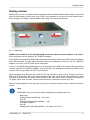
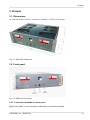
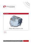
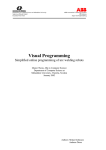
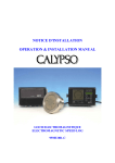
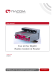
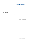
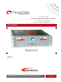
Distributed By
Radata Systems NZ Limited
Phone: 03-3133862
Email: [email protected]
User manual
.
RipEX-HS
.
version 1.1
8/1/2012
fw 1.2.x.x
RACOM s.r.o. • Mirova 1283 • 592 31 Nove Mesto na Morave • Czech Republic
Tel.: +420 565 659 511 • Fax: +420 565 659 512 • E-mail: [email protected]
www.racom.eu
Table of Contents
Getting started ..................................................................................................................................... 5
1. RipEX Hot Standby ......................................................................................................................... 7
1.1. Introduction ........................................................................................................................... 7
1.2. Key Features ........................................................................................................................ 7
1.3. Standards ............................................................................................................................. 8
2. RipEX-HS in detail ........................................................................................................................... 9
2.1. Functionality ......................................................................................................................... 9
2.2. Block diagram ..................................................................................................................... 10
2.3. Operating modes ................................................................................................................ 10
2.4. Switching over .................................................................................................................... 11
2.5. RipEX units limitations ........................................................................................................ 12
2.6. HW alarms .......................................................................................................................... 12
3. Product .......................................................................................................................................... 13
3.1. Dimensions ......................................................................................................................... 13
3.2. Front panel ......................................................................................................................... 13
3.3. Rear panel .......................................................................................................................... 16
3.4. Technical specifications ...................................................................................................... 21
3.5. Model offerings ................................................................................................................... 22
3.6. Accessories ........................................................................................................................ 22
4. Configuration ................................................................................................................................. 25
4.1. Hot-Standby ....................................................................................................................... 26
4.2. Power management ........................................................................................................... 27
4.3. Alarm settings ..................................................................................................................... 27
4.4. SNMP ................................................................................................................................. 29
5. Installation ..................................................................................................................................... 31
5.1. Mounting ............................................................................................................................. 31
5.2. Power ................................................................................................................................. 33
5.3. Grounding ........................................................................................................................... 33
5.4. Antenna .............................................................................................................................. 34
6. Troubleshooting ............................................................................................................................. 35
7. Safety, environment, licensing ....................................................................................................... 36
7.1. Frequency .......................................................................................................................... 36
7.2. Safety distance ................................................................................................................... 36
7.3. Electric power shock hazard .............................................................................................. 36
7.4. High temperature ................................................................................................................ 36
7.5. RoHS and WEEE compliance ............................................................................................ 37
7.6. Conditions of Liability for Defects and Instructions for Safe Operation of Equipment ........ 37
7.7. Important Notifications ........................................................................................................ 37
7.8. Product Conformity ............................................................................................................. 38
A. Abbreviations ................................................................................................................................ 39
Index .................................................................................................................................................. 40
B. Revision History ............................................................................................................................ 41
List of Figures
1. RipEX-HS ........................................................................................................................................ 5
2.1. Block diagram ............................................................................................................................. 10
3.1. RipeX-HS dimensions ................................................................................................................ 13
3.2. RipEX-HS front panel ................................................................................................................. 13
3.3. USB connector ........................................................................................................................... 14
© RACOM s.r.o. – RipEX-HS
3
RipEX-HS
3.4. RJ-45F ........................................................................................................................................ 14
3.5. A unit LED panel ........................................................................................................................ 15
3.6. RipEX-HS back panel ................................................................................................................. 16
3.7. RJ-45F ........................................................................................................................................ 17
3.8. Serial connector ......................................................................................................................... 17
3.9. N connector ................................................................................................................................ 18
3.10. Alarm connector ....................................................................................................................... 18
3.11. Alarms cable plug ..................................................................................................................... 18
3.12. Alarms Outputs ......................................................................................................................... 19
3.13. Power supply connector AC model .......................................................................................... 19
3.14. Battery connector ..................................................................................................................... 19
3.15. Power supply connector DC model .......................................................................................... 20
3.16. RipEX-HSB ............................................................................................................................... 23
3.17. RipEX-HSB battery connector .................................................................................................. 24
3.18. X5 adapter ETH/USB ............................................................................................................... 24
4.1. Menu Settings ............................................................................................................................ 25
4.2. Menu Hot-Stanby ....................................................................................................................... 26
4.3. Menu Alarm management .......................................................................................................... 28
5.1. HS connected as a SCADA centre redundant radio modem ..................................................... 31
5.2. RipeX-HS dimensions ................................................................................................................ 31
5.3. RipeX-HS in 19" Rack Cabinet ................................................................................................... 32
5.4. RipeX-HS montage using Assembly kit M6 – 4 pcs ................................................................... 32
5.5. RipeX-HS grounding in a cabinet ............................................................................................... 33
List of Tables
3.1. USB pin description .................................................................................................................... 14
3.2. Connections for the Ethernet to cable connector ....................................................................... 14
3.3. LED panel description ................................................................................................................ 15
3.4. Key to LEDs ............................................................................................................................... 15
3.5. Connections for the Ethernet to cable connector ....................................................................... 17
3.6. COM1,2 pin description .............................................................................................................. 17
3.7. Alarms description ...................................................................................................................... 18
7.1. Worst case Minimum Safety Distance ........................................................................................ 36
4
RipEX-HS – © RACOM s.r.o.
Getting started
Getting started
RipEX-HS serves as a redundant station equipped with two standard RipEX radio modems using a hot
stand by functionality. All you have to do to put it into operation is to connect it to an antenna and a
power supply and configure internal RipEX units using a PC and a web browser.
Fig. 1: RipEX-HS
RipEX access defaults: IP 192.168.169.169/24, username: admin, password: admin or IP 10.9.8.7
when accessing over the optional “X5” USB/ETH adapter.
When RipEX is assembled in RipEX-HS chassis and Hot standby mode is set, ETH interface of inactive
unit is disconnected. The only option to access inactive unit (typically unit “B”) is to use “X5” USB/ETH
adapter or to press “Unit B” button on the front panel.
Power on the RipEX-HS and wait approx. for 25 seconds for the RipEX OS to boot. When accessing
over the optional “X5” USB/ETH adapter, your PC will get its IP settings from the built-in DHCP server
and you have to type https://10.9.8.7 in your browser.
When accessing over Ethernet, set a static IP 192.168.169.x/24 on your PC first, Connect your PC to
RipEX “A” ETH interface, start your browser and type https://192.168.169.169 in the address line. When
you want to access Unit “B”, press “Unit B” button on the front panel. When you want to access Unit
“A” again, press “Unit A” button. Please note that there is a protective timeout of 30 sec.
When accessing RipEX for the first time, you have to accept the https security certificate issued by
Racom.
Note
Both RipEX units are in factory default settings with exceptions such as:
•
•
•
Both units:
Settings/Device/Hot Standy - set to “On”
Unit “A”:
Settings/Device/Hot Standy/MAC – “own”
Unit name: RipEX A
Unit “B”:
Settings/Device/Hot Standy/MAC – the same as in unit “A”
© RACOM s.r.o. – RipEX-HS
5
Getting started
Unit name: RipEX B
Important
You will find the details of the general settings for RipEX units in the RipEX User Manual,
and the details for RipEX-HS in Chapter Chapter 4, Configuration of the same document.
6
RipEX-HS – © RACOM s.r.o.
RipEX Hot Standby
1. RipEX Hot Standby
1.1. Introduction
RipEX-HS is designed to be used on critical sites, where high stress on HW reliability is required –
typically master or repeater stations.
RipEX-HS is assembled with 2 standard RipEX units, each powered by its independent power supply.
Controller takes care of the automatic changeover in case of failure. Changeover conditions are widely
configurable. Since both units are hot-stand-by and use identical MAC addresses, an exceptional
switch-over time of less than 2s is reached.
LED panels, Mode buttons, HW alarm outputs, SNMP traps and standard RipEX units inside make
RipEX-HS configuration and control quite easy and maintenance can be done by anyone familiar with
RipEX .
Power can be backed-up using RipEX-HSB battery pack, individual 19" rack 3U box. There are separate
batteries for RipEX “A” and “B” power supplies which allows approx. 10 hours of RipEX-HS operation.
1.2. Key Features
•
Exceptional switch-over time
○ Less than 2 s
•
Standard RipEX units used
○ In case of failure, standard RipEX unit inside can be replaced even on site.
•
SW free controller
○ There is no SW in the controller
○ No danger of SW bugs
•
Compact dimensions
○ 19" rack 3U box
•
Easy to configure and maintain
○ 4 buttons for Operating mode setting
○ LED panels for each internal RipEX unit
○ Standard RipEX web interface
○ All user connectors on rear panel
•
Two power supplies
○ Each unit powered by its own independent power supply
○ Each power supply has got its input connector, switch and fuse
○ No single point of failure in terms of power
•
Different models for power supply
○ 100–240 VAC 50–60 Hz
○ 36–60 VDC, positive grounding possible
•
Battery back-up
○ “RipEX-HSB – Battery pack” available for AC power model
○ Separate batteries for RipEX “A” and “B”
○ Batteries are charged-up from RipEX-HS
© RACOM s.r.o. – RipEX-HS
7
RipEX Hot Standby
○ Individual 19" rack 3U box
○ Approx. 10 hours of RipEX-HS operation
•
HW alarm outputs
○ 4 HW alarm outputs available on the screw terminal connector on the rear panel
○ Standard RipEX HW alarms of units “A” and “B”
○ Switch HW alarm informs active unit failure and controller switch-over to the back-up unit
○ Power alarm informs controller board power drop-out
•
Antenna connections
○ By default one antenna connector connected to active unit
○ Available model with separate “A” and “B” antenna connectors when redundant antennas are
used
○ When RipEXes with separated Rx and Tx antenna connectors are used, both respective models
are available too
1.3. Standards
Spectrum (art 3.2)
ETSI EN 300 113-2 V1.5.1
FCC Part 90
EMC (art 3.1.b)
ETSI EN 301 489-1 V1.9.2
ETSI EN 301 489-5 V1.3.1
Electrical Safety (art EN 60950-1:2006
3.1.a)
EN 60950–1:2006/A11:2009,
EN 60950–1:2006/A12:2011,
EN 60950–1:2006/A1:2010
IP rating
IP20
ETH
IEEE 802.3i
IEEE 802.3u
IEEE 802.3af
RS232
EIA-232-F
RS485
EIA RS-485
IEC101
IEC 60870-5-101
IEC104
IEC 60870-5-104
DNP3
IEEE 1815-2010
Profibus DP-V0
IEC 61158 Type 3
8
RipEX-HS – © RACOM s.r.o.
RipEX-HS in detail
2. RipEX-HS in detail
2.1. Functionality
There are two standard RipEX units with identical configurations inside RipEX-HS. Both units are
booted, however only one is active. Interfaces (COM1, COM2, Ethernet, Radio) of the second unit are
disconnected.
Note
Even if Rx on inactive RipEX unit LED panel is blinking when the active unit is transmitting,
these packets are not received. i.e. they don’t take part in Statistic, Neighbours or Graphs.
When the active unit HW alarm output changes to “On” (when a controlled value exceeds the respective
threshold), the controller automatically switches all interfaces (COM1, COM2, ETH, ANT–if applicable)
to the second unit and it takes over all functions. Since both units are using the same MAC addresses
(MAC cloning), there is a minimal drop-out while switching, less than 2s.
Possible controlled values by HW alarm output are: RSS, DQ, TXLost[%] – lost packets on Radio
channel, Ucc - power voltage, Temp – inside temperature, PWR – RF power, VSWR – reflected RF
power, ETH[Rx/Tx], COM1[Rx/Tx], COM2[Rx/Tx] – No of received/transmitted packets on respective
interfaces. For recommended settings see chapt. Chapter 4, Configuration.
SNMP trap with each switch-over can be sent (depending on configuration) to central SNMP management.
© RACOM s.r.o. – RipEX-HS
9
RipEX-HS in detail
2.2. Block diagram
Battery A
RipEX A
USB_A
USB
Power A
USB A
Power
COM1 A
Primary
power A
Manual switch
Power supply A
COM2 A
Power A
COM2
Antenna
connector
Ethernet
10/100
Base-Tx
Ethernet A
A
B
AUTO
AUTO TOGLE
Antenna
connector
A
COM1
Alarm
output
Alarm
input
AO A
AI A
COM1
COM1
Ethernet
10/100
Base-Tx
Ethernet
10/100
Base-Tx
Ethernet Switch
10/100 Base-Tx
Antenna
Relay
Controller
Antenna
connector
Ethernet
10/100
Base-Tx
COM2
COM2
RipEX B
AI B
AO B
Alarm
contacts
A
B
BACK UP
PWR
Alarm
output
Ethernet
10/100
Base-Tx
Ethernet B
Primary
power B
Alarm
input
COM2 B
Power supply B
Antenna
connector
COM2
Power B
COM1 B
Power B
USB B
USB B
COM1
Antenna
connector
B
Power
USB
Battery B
Fig. 2.1: Block diagram
2.3. Operating modes
•
•
•
•
Auto – primary active is RipEX “A”, when it fails, controller automatically switches-over to RipEX
“B”. When both units are with alarms, “A” unit remains active.
Auto toggle – the same as Auto mode, in addition after set time controller automatically switchesover to RipEX “B”, even if “A” doesn't have any alarm and uses “B” for set period in order to confirm,
that RipEX “B” is fully ready-to-operate.
A – only RipEX “A” is active and controller will never switch to RipEX “B”
B – only RipEX “B” is active and controller will never switch to RipEX “A”
Auto toggle is the most recommended mode if there are no specific requirements, because unit „B“
functionality is actively and periodically checked.
Auto mode has got minimum number of switch-overs, i.e. minimal possibility of eventual loss of packets
in internal RipEX buffers.
A and B modes are supposed to be used only for the maintenance/testing and not for normal service.
Note
Auto toggle mode is HW default, i.e. the RipEX-HS is in this mode after power cycle.
10
RipEX-HS – © RACOM s.r.o.
RipEX-HS in detail
2.4. Switching over
In order to achieve maximum reliability, the controller is software free. Switching-over is based only on
HW alarm outputs of RipEX units and the HW signals from their power supplies.
The HW alarm of active RipEX or its power supply will cause the immediate and unconditional switchover to hot-stand-by RipEX. If there are any packets waiting in queues of RipEX which becomes inactive,
these packets are discarded after switch-over.
2.4.1. Unit alarm
(=RipEX HW alarm output is “On”) becomes active based on Alarm management settings:
RSS, DQ, TXLost[%] – lost packets on Radio channel, Ucc – power voltage, Temp – inside temperature,
PWR – RF power, VSWR – reflected RF power, ETH[Rx/Tx], COM1[Rx/Tx], COM2[Rx/Tx] – No of received/transmitted packets on respective interfaces. For recommended settings see chap. Chapter 4,
Configuration.
Note
At least 10 data values have to be averaged before checking for a possible alarm. Since
different parametres are sampled over different periods, different times are required to obtain
correct values:
Ucc, Temp – approx. 10 sec. after booting
PWR, VSWR - approx. 10 sec. after booting and after the first transmission
Others – approx. 200 sec. of respective communication
2.4.2. Power alarm
(=power supply of respective unit is “Off”) when:
•
•
There is no voltage on the input terminals of power supply and battery voltage is lower than 20.5
V DC, where applicable
There is no voltage on the output terminals of power supply
Some borderline examples for Auto and Auto toggle modes (Primary unit is always “A” in Auto mode,
“A” or “B” in Auto toggle mode. The second unit is Stand-by):
1.
2.
3.
Power alarm of Primary unit is “On”
- Stand-by unit becomes active
Primary unit alarm is “On” and Power alarm of Stand-by is “On” or Stand-by unit alarm is “On”
- Nothing will be done. Primary unit remains active
Primary unit alarm is “On”, it was switched to Stand-by unit, Primary unit alarm disappeared
- it will be switched back to Primary unit immediately (the protective timeout of 30 s will be held for
shorter HW alarm output changes)
2.4.3. SNMP information about switching
When set (see chap. Section 4.4, “SNMP”), the SNMP trap with the information on the identity of the
active unit will be sent by the unit which becomes active (the “Unit name” is inside the trap)
© RACOM s.r.o. – RipEX-HS
11
RipEX-HS in detail
Note
When testing, please wait between each switch-over for at least 30 seconds. A protective
timeout of 30 s for the next switch-over will be kept after each change-over.
2.5. RipEX units limitations
When Hot Standy mode in RipEX unit is set, there are some limitations:
1.
2.
3.
4.
5.
CD pin on COM1 is used internally, it is not available to the user
HW alarm input is used internally, it is not available to the user
Save and Sleep modes are not available
Alarm limitations:
Some alarms that cause switch-over from Primary to Stand-by unit remain active. The values are
not measured after switch-over, because respective interfaces have been disconnected. These
alarms can be manually cleared using a Save button in Diagnostic/Neighbours menu or they will
be cleared when the log is automatically saved after its Log save period expired. This limitation is
valid for following alarms:
• RSScom
• DQcom
• ETH[Rx/Tx]
• COM1[Rx/Tx]
• COM2[Rx/Tx]
SNMP - If both SNMP Alarm and HW alarm outputs are set for the same event the SNMP trap will
not be sent out. See chap. Section 4.4, “SNMP”.
2.6. HW alarms
In order to achieve maximum reliability, the controller is software free. Switch-over is based only on
HW alarm outputs of RipEX units and their power supplies.
12
RipEX-HS – © RACOM s.r.o.
Product
3. Product
3.1. Dimensions
19" rack 3U, 482 W × 401 D × 133 H mm, 18.98 W × 15.79 D × 5.24 H inch.
Fig. 3.1: RipeX-HS dimensions
3.2. Front panel
Fig. 3.2: RipEX-HS front panel
3.2.1. Connectors available on front panel
RipEX uses USB 1.1, Host A interface. USB interface is wired as standard:
© RACOM s.r.o. – RipEX-HS
13
Product
Connectors USB A, USB B
Tab. 3.1: USB pin description
USB pin
signal
wire
1
+5 V
red
2
Data(−)
white
3
Data (+)
green
4
GND
black
1
2 3
4
Fig. 3.3: USB connector
The USB interface is designed for connection to the "X5" – external ETH/USB adapter. "X5" is an op1
tional accessory to RipEX, for more see Section 5.3, “Connecting RipEX to a programming PC ” - user
manual for RipEX. The adapter is used for service access to RipEX’s web configuration interface.
Both USB A and USB B are internally hard-wired to the corresponding RipEX unit.
ETH connector
Standard RJ45 connector 10/100 BaseT Auto MDI/MDIX - connected to the internal ETH switch.
Please note: only active RipEX unit can be accessed using the ETH interface
Tab. 3.2: Connections for the Ethernet to cable connector
PIN Signal
1
Direct cable Crossed cable
1
TX+
orange – white green – white
2
TX−
orange
3
RX+
green – white orange – white
4
—
blue
blue
5
—
blue – white
blue – white
6
Rx−
green
orange
7
—
brown – white brown – white
8
—
brown
green
Fig. 3.4: RJ-45F
brown
http://www.racom.eu/eng/products/m/ripex/bench-test.html#connect-PC
14
RipEX-HS – © RACOM s.r.o.
Product
3.2.2. LED panels description
Tab. 3.3: LED panel description
Symbol Description
1
ACT
2
green – RipEX A is active
dark – RipEX A is not active
PS
green – input (primary) power supply A is
OK (ON)
dark – the power supply A is without power
or is powered by battery
3
BAT
red – battery voltage is less then 22 V
dark – battery disconnected or battery
voltage is OK
4
ALARM
Fig. 3.5: A unit LED panel
red – RipEX is in alarm status
dark – no alarms
The lower row of LEDs have the same meaning as the LEDs on RipEX LED panel.
Tab. 3.4: Key to LEDs
STATUS
TX
RX
COM2
COM1
ETH
PWR
Color
Description
Green
RipEX OS (Linux) is running successfully
Dark
Reset button has been pressed
Green flashes slowly
reset five-seconds after pressing the Reset button
Green flashes quickly
default access 15-seconds after pressing the Reset
button
Red
Status alarm
Red
transmitting to radio channel
Green
receiver is synchronised to a packet
Yellow
there is a signal stronger than
−80 dBm on Radio channel
Green
receiving data
Yellow
transmitting data
Green
receiving data
Yellow
transmitting data
Yellow ON
100 Mb/s speed
Yellow OFF
10 Mb/s speed
Green ON
connected
Green flashes
ethernet data
Green
powered successfully
Blinks with a period of 1 sec Save mode
Flashes once per 3 sec
© RACOM s.r.o. – RipEX-HS
Sleep mode
15
Product
3.2.3. Buttons
Active when green LED is on:
Auto toggle – the same as Auto mode, in addition after set time controller
automatically switches-over to RipEX „B“, even if “A” doesn't have any alarm
and uses “B” for set period in order to confirm, that RipEX „B“ is fully ready-tooperate.
Auto – primary active unit is RipEX „A“, and the controller automatically switchesover to RipEX „B“ when “A” fails. When both units fail, unit „A“ remains active.
A – Unit A is active. It will never switch to the B unit. This mode is recommended
only for the maintenance/testing use and not for normal service.
B – Unit B is active. It will never switch to the A unit. This mode is recommended
only for maintenance/testing use and not for normal service.
For more see chap. Section 2.3, “Operating modes”.
Note
When testing the changeover, please wait at least 30 seconds between individual tests.
3.3. Rear panel
100–240 VAC (48 VDC)
"B" unit
Battery pack
"B" unit
Redundant ANT
or (separate Rx ANT)
COM1
RS232
COM2
RS232/485
ETH
Battery pack
"A" unit
HW alarm outputs:
"A", "B", Switch, Power
100–240 VAC (48 VDC)
"A" unit
ANT
(separate Tx ANT)
Fig. 3.6: RipEX-HS back panel
3.3.1. Common connectors
ETH connector
2× ETH
16
RipEX-HS – © RACOM s.r.o.
Product
Standard RJ45 connector 10/100 BaseT Auto MDI/MDIX - connected to the internal ETH switch.
Tab. 3.5: Connections for the Ethernet to cable connector
PIN Signal
Direct cable Crossed cable
1
TX+
orange – white green – white
2
TX−
orange
3
RX+
green – white orange – white
4
—
blue
blue
5
—
blue – white
blue – white
6
Rx−
green
orange
7
—
brown – white brown – white
8
—
brown
green
Fig. 3.7: RJ-45F
brown
COM1, COM2
RipEX HS provides two serial interfaces COM1 and COM2 terminated by DSUB9F connectors. COM1
is always RS232, COM2 can be configured as RS232 or RS485.
- both COMs are internally switched to the active RipEX unit.
RipEX‘s RS232 is a hard-wired DCE (Data Communication Equipment) device. Equipment connected
to the RipEX’s serial ports should be of DTE (Data Terminal Equipment) type and a straight-through
cable should be used. If a DCE device is connected to the serial ports RipEX, a null modem adapter
or cross cable has to be used.
Tab. 3.6: COM1,2 pin description
DSUB9F
COM1, 2 – RS232
COM2 – RS485
pin
signal
In/ Out
signal In/ Out
1
CD
O
—
2
RxD
O
line B
I/O
3
TxD
I
line A
I/O
4
DTR
I
5
GND
—
GND
6
DSR
O
—
7
RTS
I
—
8
CTS
O
—
9
—
—
—
Fig. 3.8: Serial connector
Antenna
There are different models in terms of antenna connectors, see chap. Section 3.5, “Model offerings”.
N-female connector is always used.
© RACOM s.r.o. – RipEX-HS
17
Product
Fig. 3.9: N connector
Alarms
PWR
S
+
B
A
Lead
Binding
Screws (7)
ALARMS
Wire
Ports (7)
Retaining
Screws (2)
Fig. 3.10: Alarm connector
Fig. 3.11: Alarms cable plug
Tab. 3.7: Alarms description
Symbol Description
A
– alarm status of Ripex A - open collector
– internally connected to GND when unit is not
in alarm status
B
– alarm status of Ripex B - open collector
– internally connected to GND when unit is not
in alarm status
–
– connected to ground
+
– connected to +24 V power (max. 5 mA)
S
– open collector - internally connected to GND
when unit A is active
- i.e. not switched to backup unit
PWR
– internal power alarm - open collector
– internally connected to GND when controller
power source is OK
18
RipEX-HS – © RACOM s.r.o.
Product
PWR
S
+
B
PWR
A
S
Alarm status A
Alarm status B
max. 30 V DC
5 mA
max. 30 V DC
5 mA
PWR
S
+
B
A
PWR
S
+
B
A
+
B
A
Active B
PWR fail
max. 30 V DC
5 mA
max. 30 V DC
5 mA
Fig. 3.12: Alarms Outputs
3.3.2. A and B connectors
Power supply connector AC model
100–240 VAC equipped with T2.5A fuse
Fig. 3.13: Power supply connector AC model
Battery connector AC model
+ to be connected with + pole of 24 V battery
– to be connected with - pole of 24 V battery
Important
internally without a fuse
Fig. 3.14: Battery connector
© RACOM s.r.o. – RipEX-HS
19
Product
Power supply connector DC model
Fig. 3.15: Power supply connector DC model
20
RipEX-HS – © RACOM s.r.o.
Product
3.4. Technical specifications
Radio parameters
The same as RipEX units used
Electrical
Primary power
HW models:
100–240 VAC, 50–60 Hz
36–60 VDC, positive grounding possible
Individual power supply for each RipEX unit
Interfaces
Ethernet
3× switched 10/100 Base-T Auto MDI/MDIX RJ45
RS232
COM 1
DB9F
300–115 200 bps
RS232/RS485 SW configurable
COM 2
DB9F
300–115 200 bps
USB
2× USB 1.1 for each RipEX unit
Host A
Antenna
50 Ω
N-female(s)
HW models (according to Antenna)
1× N-female – Rx/Tx, switched
2× N-female – Rx/Tx, separate for each RipEX unit
2× N-female – separate Rx and Tx, switched
4× N-female – separate Rx and Tx, separate for each RipEX unit
Enviromental
IP Code (Ingress Protection)
IP20
MTBF (Mean Time Between Fail- > 100 000 hours
ure)
Operating temperature
−10 to +60 °C (14 to +140 °F)
Humidity
5 to 95 % non-condensing
Storage
−40 to +85 °C (−40 to +185 °F)/5 to 95 % non-condensing
Mechanical
Dimensions
19" rack 3U 482 W × 401 D × 133 H mm (18,98 × 15.79 × 5,24 in)
Weight
7.1 kg (15.7 lbs), RipEX unit exl.
9.1 kg (20.1 lbs), RipEX unit incl.
Diagnostic and Management
Standard for individual RipEX units used
LED panels
for each RipEX unit: standard RipEX LED panel (7× tri-color LEDs: Power, ETH,
COM1, COM2, Rx, Rx, Status)
+ 4× two-color LEDs: Active, Power supply, Battery, Alarm
HW Alarm outputs
RipEX A, RipEX B, Switch, Power
Approvals
CE, FCC
© RACOM s.r.o. – RipEX-HS
21
Product
3.5. Model offerings
RipEX-HS has been designed to have minimum possible number of hardware variants. Different HW
models are determined by power supplies and antenna connections.
3.5.1. Ordering code (Part No’s)
Trade name:
RipEX-HS
Type:
RipEX-HS
Code
(according to power supply and antenna connectors): e.g. RipEX-HS-AO, RipEX-HSDR etc.
RipEX-HS-XY
X – power:
A – 100–240 VAC 50–60 Hz
D – 36–60 VDC
Y – antenna connectors:
O – one antenna (switched for A and B)
R – separate antennas for A and B units (no switching, redundant antennas)
S – separate antennas for Tx and Rx (switched for A and B units, RipEX-D model used)
3.6. Accessories
3.6.1. RipEX-HSB
•
•
•
•
•
•
2
Back-up battery pack
Separate batteries for RipEX “A” and “B”
Batteries are charged-up from RipEX-HS (AC power version)
Individual 19" rack 3U box
2
Space for 4x 12 V / 7.2 Ah, FASTON.250 (6.3 mm), e.g. Panasonic LC-R127R2P
Approx. 10 hours of RipEX-HS operation
http://www.panasonic.com/industrial/includes/pdf/Panasonic_VRLA_LC-R127R2P.pdf
22
RipEX-HS – © RACOM s.r.o.
Product
Fig. 3.16: RipEX-HSB
Electrical
battery pack
RipEX-HSB
Output 2× 24 V/7.2 Ah
Enviromental
Operating temperature
−15 to +50 °C (14 to +140 °F)
Humidity
25 to 85 % non-condensing
Storage
−15 to +40 °C (−40 to +185 °F)
max. 30 °C recommended, 5 to 95 % non-condensing
Mechanical
Dimensions
Weight
19" rack 3U
482 W × 345 D × 133 H mm (18,98 × 13.58 × 5,24 in)
3.5 kg (7.7 lbs), batteries exl.
13.1 kg (28.9 lbs), batteries incl.
For more information about the operation of Lead Acid batteries, see http://www.panasonic-industrial.com/pf_vrla
© RACOM s.r.o. – RipEX-HS
23
Product
Fig. 3.17: RipEX-HSB battery connector
3.6.2. X5 - ETH/USB adapter
•
•
•
For service access to the RipEX web interface via USB connector
Built-in DHCP server
To access the RipEX always use the fixed IP 10.9.8.7
3
For more refer to RipEX User Manual .
The USB interface is designed for the connection to the "X5" –
external ETH/USB adapter. The "X5" is an optional accessory
to
RipEX,
for
more
see
h t t p : / / w w w. r a com.eu/eng/products/m/ripex/bench-test.html#connect-PC. The
adapter is used for service access to RipEX’s web configuration
interface.
Fig. 3.18: X5 adapter ETH/USB
3
http://www.racom.eu/eng/products/m/ripex/bench-test.html#connect-PC
24
RipEX-HS – © RACOM s.r.o.
Configuration
4. Configuration
Connection and configuration of the active RipEX unit inside of RipEX-HS is the same as for standard
RipEX. Use either X5 - ETH/USB adapter ( http://www.racom.eu/eng/products/m/ripex/benchtest.html#connect-PC) or Ethernet interface where RipEX access defaults are: IP 192.168.169.169/24,
username: admin, password: admin Inactive RipEX unit can be reached only via X5 adapter.
For more details see chap. Getting started.
The settings of all parameters have to be identical. The only exception is the Unit name - it shall be
different and preferably contains A character A for unit A and character B for unit B (e.g. Unit A).
To be sure that the setting of both units are identical it is recommended to set unit A, thereafter save
the settings to a file (Maintenance -Configuration - Save to file) and use this setting for unit B (Maintenance -Configuration - Restore - File path - Upload) and change the Unit name.
Note
Be careful to set RipEX units inside of RipEX-HS to their factory defaults. If you do that,
both units will have the same Ethernet IP address and their Operating mode is Bridge. While
configuring you could be accessing the second unit over the air without being aware of it.
In such a case use X5 - ETH/USB adapter.
Fig. 4.1: Menu Settings
© RACOM s.r.o. – RipEX-HS
25
Configuration
4.1. Hot-Standby
Fig. 4.2: Menu Hot-Stanby
4.1.1. Hot Standby – set to On
When RipEX unit is used in RipEX-HS and Hot Standy is „On“ there are some limitations with it. Specifically, CD pin on COM1 and HW alarm Input and Output are used internally and not available to the
user. Neither Save nor Sleep modes can be activated. Please refer RipEX-HS User manual.
All settings below are valid only for RipEX units in RipEX-HS equipment, where two units in Hot Standby
mode are running. Both units MUST have the same settings! Only Unit names should be different as
this parameter is used in SNMP to recognize the sender of SNMP traps. In order to ensure that the
settings of both units are identical, it is recommended to set unit “A”, thereafter save its settings into a
file (Maintenance/Configuration/Save to file) and use these settings for unit “B”. (Maintenance/Configuration/Restore/File path/Upload) Finally, a unique Unit name should be assigned to Unit B.
List box: Off, On
Default = Off
When “On”, HW switching from RipEX unit “A” to RipEX unit “B” is performed based on the HW Alarm
Output settings in Settings/Alarm management. RipEX “A” is the primary unit, , Unit “B” is activated if
there is HW alarm on unit “A” or unit “A” power source is down or when Auto Toggle Period expired.
When mentioned events passed, RipEX “A” goes to be active again.
•
MAC
Both units in RipEX-HS are using the same MAC addresses (MAC cloning). Whichever unit is active
(either “A or B”), RipEX Ethernet interface will use this MAC address. This MAC address has to be
unconditionally set to the same value in both units used in RipEX-HS. Otherwise, the switching
between units will not function properly.
Read own – it is possible to download the MAC address of this unit. The value in the second unit
has to be manually set to the same value then
•
26
Auto Toggle mode
When Auto Toggle mode is On (HW button on front panel), controller automatically switches-over
to RipEX ”B“, even if “A” doesn't have any alarm and uses “B” for a set time in order to confirm that
RipEX ”B“ is fully ready-to-operate.
RipEX-HS – © RACOM s.r.o.
Configuration
○ Start Date [YYYY-MM-DD]
Fill in the Date in the required format when Auto Toggle mode starts.
○ Start Time [HH:MM:SS]
Fill in the Time in the required format when Auto Toggle mode starts on ”Start Date“ day.
○ Period [min.]
Minimum value 60 min.
Within this period units “A” and “B” will change their activities over. Unit “A” starts to operate at
“Start Date and Time”. When “Period” minus “Unit B” time expires, controller switches to unit
“B”.
○ Unit B [min.]
Minimum value 5 min.
Time when unit “B” will be active within “Period”. It has to be shorter than Period by 5 min.
In the example above (Fig. 4.2, “Menu Hot-Stanby”) a toggle will cause changing the active unit once
per week (10,080 minutes) at midnight with the first week is starting on the date set above.
4.2. Power management
Set to Always On. Save and Sleep modes are not available when Hot standby.
4.3. Alarm settings
4.3.1. Switch-over alarms
You can set the alarms to cause a switch-over to the hot-stand-by unit.
© RACOM s.r.o. – RipEX-HS
27
Configuration
Fig. 4.3: Menu Alarm management
Enabled HW Alarm Output will be used for switching from this active unit to the inactive one, when the
specific value is detected outside the Min Value - Max value range alarm will be declared and switching
process is started.
Thresholds shall be set according the needs of the actual network:
RSScom Max value shall be set to the designed RSS value plus a designed fade margin (e.g. 80+20
dBm), Min value can be 0 - stronger signal typically will not cause problems.
DQcom
more significant communication troubles start with values less than 100; all values above
should be sufficient
RSScom and DQcom shall together indicate even partial damage or problem with RipEX
unit receiver parts or coaxial feedline cable or antenna. Equally, the problem can be on the
transmitter part of RipEX unit, coaxial feedline cable or antenna of transmitter counterpart(s).
TXLost
the value will indicate problems with packet deliveries to communicating parties. It is cumulative percentage of lost packet on Radio channel (acknowledge has not been received).
Applicable only in Router mode.Exercise caution when setting this alarm. Keep in mind, that
problems of counterpart unit(s) can also be reflected here. E.g. counterpart doesn’t receive
packets or doesn’t transmit acknowledges.
Min value shall be set to 0, Max value to tens of % (e.g. 50).
Ucc
28
since power supply for RipEX unit is controlled independently, this alarm is not recommended
to be used for switch-over to Standby unit. However it can be used for SNMP trap informing
RipEX-HS – © RACOM s.r.o.
Configuration
about main power failure and switch to battery back-up. Min value shall be set to lower than
24.5, Max value to the maximal voltage limit for charging the battery (e.g. 29).
Temp
the temperature of both RipEX units inside of RipEX-HS will probably be the same, so it
doesn’t make any sense to use this alarm for switch-over. However this alarm can be used
in case of hard duty cycle for switching between both units; Max value in such a case should
be set approximately to 65.
PWR
this value shall be set to a set value of power with a margin of ± 25-30%. Alarm will be active
in case of faulty transmitter part of active RipEX.
VSWR
this value mostly indicates problem with antenna or antenna feed line coaxial cable. When
RipEX-HS-xO (one antenna switched for A and B units), a switch-over to unit B will probably
not help. Recommended values vary between 1 and 3.
ETH[Rx/Tx], COM1[Rx/Tx],
COM2[Rx/Tx]
these three values represent No of received/transmitted packets on
respective interfaces. They are mainly applicable for polling type
applications network. Each communication has got one request and
one reply, so the number of Rx and Tx packets should then be the
same (Rx/Tx=1) . these alarms should not be used For report by
exception networks.
4.4. SNMP
In the same window (Fig. 4.3, “Menu Alarm management”) one can set whether a SNMP trap should
be sent when respective alarm occurs.
If both SNMP Alarm and HW alarm outputs are set for the same event the switch-over to the second
RipEX unit will be carried out and the RipEX with alarm itself has no time for sending the SNMP trap
out. Only events set on the Alarm management window and not set as HW alarm Output will be processed.
The SNMP trap message will be sent both when a parameter value exceeds the alarm threshold and
when it returns back into its “normal” range.
For more information about SNMP settings refer to RipEX User manual http://www.racom.eu/download/hw/ripex/free/eng/ripex-m-en.pdf
© RACOM s.r.o. – RipEX-HS
29
Configuration
Note
Since the units have got the same configurations ( same IP addresses), the unique identifier
in SNMP trap is the “Unit name” (menu Settings/Device). It is recommended to set different
names for A and B units (default RipEX A and RipEX B).
30
RipEX-HS – © RACOM s.r.o.
Installation
5. Installation
Fig. 5.1: HS connected as a SCADA centre redundant radio modem
Both serial and Ethernet SCADA masters are supported.
5.1. Mounting
Fig. 5.2: RipeX-HS dimensions
© RACOM s.r.o. – RipEX-HS
31
Installation
Fig. 5.3: RipeX-HS in 19" Rack Cabinet
Fig. 5.4: RipeX-HS montage using Assembly kit M6 – 4 pcs
32
RipEX-HS – © RACOM s.r.o.
Installation
5.2. Power
5.2.1. 100–240 V AC, 50–60 Hz
Since there are two independent power supplies, one for each RipEX unit, it is recommended to connect
each power supply to a separate power phase with individual circuit breakers. When one phase would
be off, RipEX-HS will still be On.
There are individual power connectors for each power supply. See chap. Section 3.3.2, “A and B connectors”.
5.2.2. 36–60 V DC
There are also two independent power supplies with 36 to 60 V DC input voltage, one for each RipEX
unit; input conductors are isolated from the rest of the RipEX-HS and thus allows positive or negative
grounding. The electric strength is 4 kV AC/1 min.
There are individual power connectors for each power supply. See chap. Section 3.3.2, “A and B connectors”.
5.2.3. Back-up
When back-up battery is required, RipEX-HSB battery pack can be connected. RipEX-HSB is individual
19" rack 3U box assembled with separate batteries for RipEX “A” and “B”. There is space for 4x 12 V
/ 7.2 Ah batteries inside. Batteries are charged-up from RipEX-HS. RipEX-HSB provide approx. 10
hours of RipEX-HS operation.
Note
Primary AC power has to be active first, otherwise the battery back-up will not be working.
5.3. Grounding
The grounding screw on the rear panel has to be properly connected to the grounding point of the rack.
2
The minimal required copper conductor cross-section is 4 mm .
Fig. 5.5: RipeX-HS grounding in a cabinet
© RACOM s.r.o. – RipEX-HS
33
Installation
5.4. Antenna
For antenna installation refer to RipEX User manual – http://www.racom.eu/eng/products/m/ripex/instal.html#antenna-mount
34
RipEX-HS – © RACOM s.r.o.
Troubleshooting
6. Troubleshooting
For trouble with individual RipEX units please refer to RipEX User Manual Chap. 9. Troubleshooting
1.
The switch-over works, but the Eth connection starts working with some delay
- Check if MAC addresses are really identical for both active and inactive units
2.
Automatic switch-over does not take place:
- Make sure that A or B mode is not used, Auto or Auto Toggle mode has to be used.
3.
The switch-over takes place due to problems with powering but not if a problem with RipEX unit
occurs
- check the setting of alarms and thresholds for both RipEX units with focus to the specific problem
4.
The switch-over takes place even if it is not required
- check the Diagnostic part of Status menu, eventually Graphs, check if the thresholds and alarms
used are in accordance with type of network used - for details see chap. Section 4.3, “Alarm settings”.
© RACOM s.r.o. – RipEX-HS
35
Safety, environment, licensing
7. Safety, environment, licensing
7.1. Frequency
The radio modem must be operated only in accordance with the valid frequency license issued by national frequency authority and all radio parametres have to be set exactly as listed.
Important
Use of frequencies between 406.0 and 406.1 MHz is worldwide-allocated only for International Satellite Search and Rescue System. These frequencies are used for distress beacons
and are incessantly monitored by the ground and satellite Cospas-Sarsat system. Other
use of these frequencies is forbidden.
7.2. Safety distance
Safety distances with respect to the US health limits of the electromagnetic field intensity
are in Minimum Safety Distance tables below, calculated for different antennas and
RipEX power levels. The distances were calculated according to (doplnit normu) and
apply to far-field region only. Whenever the result is comparable or smaller than the actual size of the respective antenna, the field intensity is even smaller than the far-field
based calculation and the safety limit is never exceeded. For output power 0.2 W or
lower the safety limit is not exceeded at any distance and any of the antennas.
Tab. 7.1: Worst case Minimum Safety Distance
Antenna Gain
5 dBi
10 dBi
15 dBi
160 MHz
2m
3m
5m
300 and 400 MHz
2m
2m
4m
For detailed Minimum Safety Distances refer to RipEX User Manual ???odkaz
7.3. Electric power shock hazard
BEFORE uncovering the RipEX HS top cover be sure that the power plug is disconnected.
It is not allowed to use the RipEX HS without the cover because of the risk of electric
power shock!
7.4. High temperature
When opening of top cover in an environment where the ambient temperature exceeds
55 °C, prevent human contact with the enclosure heatsink of the RipEXes units.
36
RipEX-HS – © RACOM s.r.o.
Safety, environment, licensing
7.5. RoHS and WEEE compliance
The RipEX is fully compliant with the European Commission‟s RoHS (Restriction of Certain Hazardous
Substances in Electrical and Electronic Equipment) and WEEE (Waste Electrical and Electronic
Equipment) environmental directives.
Restriction of hazardous substances (RoHS)
The RoHS Directive prohibits the sale in the European Union of electronic equipment containing these
hazardous substances: lead, cadmium, mercury, hexavalent chromium, polybrominated biphenyls
(PBBs), and polybrominated diphenyl ethers (PBDEs).
End-of-life recycling programme (WEEE)
The WEEE Directive concerns the recovery, reuse, and recycling of electronic and
electrical equipment. Under the Directive, used equipment must be marked, collected
separately, and disposed of properly. Racom has instigated a programme to manage
the reuse, recycling, and recovery of waste in an environmentally safe manner using
processes that comply with the WEEE Directive (EU Waste Electrical and Electronic
Equipment 2002/96/EC).
Battery Disposal—This product may contain a battery. Batteries must be disposed of properly, and
may not be disposed of as unsorted municipal waste in the European Union. See the product documentation for specific battery information. Batteries are marked with a symbol, which may include lettering to indicate cadmium (Cd), lead (Pb), or mercury (Hg). For proper recycling return the battery to
your supplier or to a designated collection point. For more information see: www.weeerohsinfo.com
7.6. Conditions of Liability for Defects and Instructions for Safe Operation
of Equipment
Please read these safety instructions carefully before using the product:
•
•
•
•
•
Liability for defects does not apply to any product that has been used in a manner which conflicts
with the instructions contained in this operator manual, or if the case in which the radio modem is
located has been opened, or if the equipment has been tampered with.
The radio equipment can only be operated on frequencies stipulated by the body authorised by the
radio operation administration in the respective country and cannot exceed the maximum permitted
output power. RACOM is not responsible for products used in an unauthorised way.
Equipment mentioned in this operator manual may only be used in accordance with instructions
contained in this manual. Error-free and safe operation of this equipment is only guaranteed if this
equipment is transported, stored, operated and controlled in the proper manner. The same applies
to equipment maintenance.
In order to prevent damage to the radio modem and other terminal equipment the supply must always
be disconnected upon connecting or disconnecting the cable to the radio modem data interface. It
is necessary to ensure that connected equipment has been grounded to the same potential.
Only undermentioned manufacturer is entitled to repair any devices.
7.7. Important Notifications
Sole owner of all rights to this operating manual is the company RACOM s. r. o. (further in this manual
referred to under the abbreviated name RACOM). All rights reserved. Drawing written, printed or repro-
© RACOM s.r.o. – RipEX-HS
37
Safety, environment, licensing
duced copies of this manual or records on various media or translation of any part of this manual to
foreign languages (without written consent of the rights owner) is prohibited.
RACOM reserves the right to make changes in the technical specification or in this product function or
to terminate production of this product or to terminate its service support without previous written notification of customers.
Conditions of use of this product software abide by the license mentioned below. The program spread
by this license has been freed with the purpose to be useful, but without any specific guarantee. The
author or another company or person is not responsible for secondary, accidental or related damages
resulting from application of this product under any circumstances.
The maker does not provide the user with any kind of guarantee containing assurance of suitability
and usability for his application. Products are not developed, designed nor tested for utilization in
devices directly affecting health and life functions of persons and animals, nor as a part of another important device, and no guarantees apply if the company product has been used in these aforementioned
devices.
RACOM Open Software License
Version 1.0, November 2009
Copyright (c) 2001, RACOM s.r.o., Mírová 1283, Nové Město na Moravě, 592 31
Everyone can copy and spread word-for-word copies of this license, but any change is not permitted.
The program (binary version) is available for free on the contacts listed on http://www.racom.eu. This
product contains open source or another software originating from third parties subject to GNU General
Public License (GPL), GNU Library / Lesser General Public License (LGPL) and / or further author licences, declarations of responsibility exclusion and notifications. Exact terms of GPL, LGPL and some
further licences is mentioned in source code packets (typically the files COPYING or LICENSE). You
can obtain applicable machine-readable copies of source code of this software under GPL or LGPL licences on contacts listed on http://www.racom.eu. This product also includes software developed by
the University of California, Berkeley and its contributors.
7.8. Product Conformity
RACOM declares that the RipEX radio modem & router is in conformity with the essential requirements and other relevant requirements of the Directive of the European
Parliament and of the Council 1999/5/EC on radio equipment and telecommunications
terminal equipment and the mutual recognition of their conformity.
The RipEX radio modem & router has been type accepted for operation by the Federal Communications Commission in accordance with Title 47 Part90 of the FCC
rules. See the label on the unit for the specific FCC ID and any other certification
designations.
38
RipEX-HS – © RACOM s.r.o.
Abbreviations
Appendix A. Abbreviations
CLI
Command Line Interface
OS
Operation System
CTS
Clear To Send
PC
Personal Computer
DCE
Data Communication Equipment
PER
Packet Error Rate
DQ
Data Quality
PWR
Power
DTE
Data Terminal Equipment
RF
Radio Frequency
EMC
Electro-Magnetic Compatibility
RipEX
Radio IP Exchanger
FCC
Federal Communications Commission RoHS
FEP
Front End Processor
GPL
General Public License
https
Hypertext Transfer Protocol Secure
IP
Internet Protocol
kbps
kilobit per second
LAN
Local Area Network
MAC
Media Access Control
MDIX
Medium dependent interface crossover
MIB
Management Information Base
NMS
Network Management System
N.C.
Normally Closed
N.O.
Normally Open
Restriction of the use of Hazardeous
Substances
RSS
Received Signal Strength
RTS
Request To Send
RTU
Remote Terminal Unit
RX
Receiver
SCADA Supervisory control and data acquisition
SDR
Software Defined Radio
SNMP
Simple Network Management Protocol
TCP
Transmission Control Protocol
TX
Transmitter
UDP
User Datagram Protocol
VSWR Voltage Standing Wave Ratio
WEEE
© RACOM s.r.o. – RipEX-HS
Waste Electrical and Electronic Equipment
39
Index
S
A
Safety, licensing, 36
SNMP, 29
standards, 8
SW settings, 25
Accessories, 22
B
Block diagram, 10
C
Common connector, 16
Configurations, 25
T
Technical specification, 21
Troubleshoting, 35
X
X5 - ETH/USB adapter, 24
D
Dimensions, 13
F
Front connectors, 13
Front panel, 13
G
GNU licence, 38
H
Hot Standby, 26
I
Installation, 31
L
LED panels, 15
M
mounting, 31
O
offerings, 22
Operating modes, 10
P
Power, 33
product
Conformity, 38
R
Rear panel, 16
RoHS and WEEE, 37
© RACOM s.r.o. – RipEX-HS
40
Revision History
Appendix B. Revision History
Revision
This manual was prepared to cover a specific version of firmware code. Accordingly, some screens
and features may differ from the actual unit you are working with. While every reasonable effort has
been made to ensure the accuracy of this publication, product improvements may also result in minor
differences between the manual and the product shipped to you.
Revision 1.0
First issue
© RACOM s.r.o. – RipEX-HS
2012-07-31
41