1
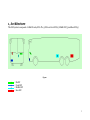
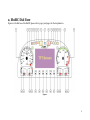
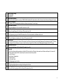
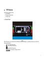
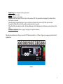
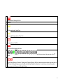
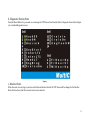
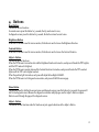
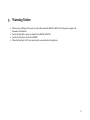
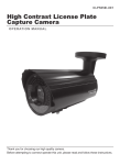
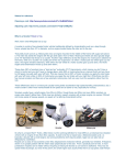
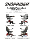
LZ BUSLINE CAN System User Manual Table of Contents Architecture 3 MultIC Dial Face 4 TFT Screen 7 Buttons 12 Notice 13 2 1, Architecture This CAN system is composed of 1 MultIC and 4 IOUs. The 3 IOUs are Front IOU(2), Middle IOU(3) and Rear IOU(4). Figure 1 1 2 3 4 : : : : MultIC Front IOU Middle IOU Rear IOU 3 2, MultIC Dial Face Figure 2 is the dial face of the MultIC, please refer to page 5 and page 6 for their explanation. Figure 2 4 1 2 3 4 5 6 7 8 9 10 11 12 Vehicle Speed Gauge Outside MPH Inside KPH Over Speed Indication When the Vehicle Speed is more than 75MPH/120KM, the Red LED inside will turn ON, at the same time, Buzzer will beep for 1 Second Turn Left Indication The Green LED will flashing and the Buzzer will beep according to Turn Left Light Hand Brake Indication When Hand Brake is ON, the Red LED inside will turn ON Low Beam Indication When the Low Beam is ON, the Green LED inside will turn ON Air Pressure Alarm Indication Air Pressure is too low, the Red LED inside will turn ON, at the same time, the Buzzer will sound Engine Preheat Indication When the Engine is preheating, the Yellow LED inside will turn ON Service Light If any faults are detected, the Yellow LED inside will turn ON and at the same time the fault Message will be displayed on the TFT Screen. For example, if the Low Beams encounter a fault, the Service Light will turn ON and a fault Message will display on the TFT Screen High Beam Indication When the High Beam is ON, the Blue LED inside will turn ON Stop Light Any of the following faults are detected, the Red LED inside will turn ON and at the same time, the Buzzer will beep for 3 seconds. If the Driver finds this light is ON, he must stop the coach and resolve the problem Low Air Pressure High Coolant Temperature Low Oil Pressure Low Coolant Level Disc Brake pad wear indicator Engine Flash Code This Yellow LED will flash according to the Engine Fault Code Front Fog Light Indication When the Front Fog Light is ON, the Yellow LED inside will turn ON 5 13 14 15 16 17 18 19 20 21 22 23 24 25 26 27 28 29 30 31 Rear Fog Light Indication When the Rear Fog Light is ON, the Yellow LED inside will turn ON ABS Warning Light When ABS encounters a fault, the Yellow LED inside will turn ON Right Turn Indication The Green LED will flashing and the Buzzer will beep according to Right Turn Light Over RPM Indication When the Engine RPM is more than 3000 RPM, the Red LED inside will turn on RPM Gauge Fuel Level Gauge Low Fuel Level Alarm Indication If the Fuel Level is less than 10%, the Red LED inside will turn ON High Coolant Temperature Alarm Indication When the Coolant Temperature is, the Red LED inside will turn ON Coolant Temperature Gauge Reset Button Please see page 12 as reference Brightness Button Please see page 12 as reference Contrast Button Please see page 12 as reference Adjust + Button Please see page 12 as reference Menu Button Please see page 12 as reference Adjust - Button Please see page 12 as reference Oil Pressure Gauge Low Oil Pressure Warning Indication If the Oil Pressure is less than 15 Psi, the Red LED inside will turn ON Low Voltage or High Voltage Warning Indication If the Voltage is lower than 23V or higher than 30V, the Red LED inside will turn ON Voltage Gauge 6 3, TFT Screen The TFT Screen has three states: a) Normal State b) Diagnostic Screen State c) Monitor State a. Normal State: Figure 3 When the system is in a normal state, the TFT Screen should be like Figure 3. According to this screen, we know the following information: In: Coach Inside Temperature. Out: Coach Outside Temperature. : Engine Cabin Temperature. Left Gauge: Air Pressure (1) Gauge is normal. 7 Right Gauge: Air Pressure (2) Gauge is normal. 89 Ml: Trip, unit is miles. 199 Ml: Odometer, unit is miles. When the front door is open, the front door of the coach on TFT will open and close frequently to indicate driver that the door is opened. When the engine compartment door is open, a small door in back of the coach on TFT will open and close frequently to indicate driver that the engine compartment door is opened. When the CAN system detects a fault, a Warning Message(s) will be displayed on the blue area on the bottom of the TFT. Indication Symbols: Please see page 7 and page 8 for symbol reference. The indication symbols are in the top row of the TFT Screen (located in A – N Place, Figure 4), see pages 9 and 10 for their explanations: Figure 4 8 A Low Coolant Level Warning, Red Color B Reversed C ASR Working Indication, Yellow Color D Position Light Working Indication, Yellow Color E Charging Indication, Red Color F Engine Cabin Open Indication, Red Color G Gear Indication, Only the Neturl Gear is Green Color, other Gears are White Color. These Symbols are shown in the same place on the TFT Screen. H Low Air Pressure Warning (Air Pressure 1 Warning and Air Pressure 2 Warning), Red Color, these two symbols are shown in the same place on TFT Screen. If both system pressures are in the Red on the Bar Graph Display, an Exclamation ( ! ) mark is shown until one of the system pressures goes into the Green on the Bar Graph Display. 9 I Brake Disc Warning Indication, Red Color, they are shown in the same place, the theory is the same as the Air Pressure Warning Symbols. FL: Front Left Brake Disc Warning FR: Front Right Brake Disc Warning ML: Middle Left Brake Disc Warning MR: Middle Right Brake Disc Warning RL: Rear Left Brake Disc Warning RR: Rear Right Brake Disc Warning J Air Filter Warning, Red Color K Wash Room Low Water Warning, Green Color L Body Up Indication, Yellow Color Body Doen Indication, Yellow Color Engine Retarder Working Indication, Red Color They are shown in the same place on TFT Screen M Reversed N Alternator Fault Indication, Green Color 10 b. Diagnostic Screen State Press the Menu Button for 3 seconds, we can change the TFT Screen from Normal State to Diagnostic Screen State. Figure 5 is a standard diagnostic screen. c. Monitor State Figure 5 When the coach is reversing or you turn on the Reverse Monitor Switch, the TFT Screen will be changed to the Monitor State, this function is just like a normal color reverse monitor. 11 4. Buttons Reset Button This button has two functions: In normal screen: press this button for 3 seconds, the trip can be reset to zero; In diagnostic screen: press this button for 3 seconds, the fault count can be reset to zero. Brightness Button When the TFT Screen is used for reverse monitor, this button is used to turn on the Brightness Function. Contrast Button When the TFT Screen is used for reverse monitor, this button is used to turn on the Contrast Function. Adjust + Button This button has four functions: When the TFT Screen is in monitor state and the Brightness Function is turned on, each press will make the TFT brighter, until the TFT reaches it’s brightest; When the TFT Screen is monitor state and the Contrast Function is turned on, each press will make the TFT’s contrast lighter until the TFT is at its highest contrast; When the position light is turned on, each press will adjust the backlight of MulitIC. When the TFT Screen is in it’s diagnostic screen state, each press will shift the screen page. Menu Button This button is used for shifting the normal screen and diagnostic screen, press this button for 3 seconds, the screen will shift to the diagnostic screen. Because the diagnostic screen has multiple pages, use the Adjust + Button or Adjust – Button to scroll through the pages of the diagnostic screen. Adjust – Button This Button has four functions and all of functions are just opposite functions of the Adjust + Button. 12 5. Warning Notice When you are welding on the coach, you must disconnect the MultIC and IOUs from the power supply and disconnect the batteries; Do not directly spill or spray any liquid on the MultIC and IOUs; Do not allow objects to touch Lens MultIC; When the Stop Light is ON, you must stop the coach and solve the problem; 13