1
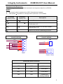
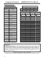
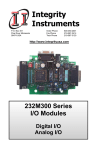
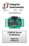
Integrity Instruments
232M300-CNT User Manual
Integrity
Instruments
P.O. Box 451
Pine River Minnesota
56474 USA
Order Phone
Fax Phone
Tech Phone
800-450-2001
218-587-3414
218-587-3120
http://www.integrityusa.com
232M300CE-CNT
232M300CT-CNT
Counter
Module
1
Integrity Instruments
232M300-CNT User Manual
Table of Contents
Introduction
Features.........................................................................................2
Quick Start ....................................................................................3
Communications
RS-232 Packet Information ...........................................................5
Counter Commands .......................................................................6
Commands and Responses
Command and Response Table ....................................................6
Command and Response Examples ............................................7
Digital I/O
Pin outs ..........................................................................................8
Introduction
This modules using RS-232 communications to access the counter data. The module has
16 digital counters made available through a DB 25 connector
I/O Module features:
MPU:
Microchip PIC18F442
EEPROM:
Microchip internal to MPU
MPU Clock: 10 Mhz
Interface:
RS-232 (single ended)
Baud:
9600, 19200, 57600, 115200 (DIP switch selectable)
LED:
Bicolor diagnostic LED
Watchdog:
MPU has built-in watchdog timer
POR:
MPU contains timed Power On Reset circuitry
Brownout:
MPU brownout detection ciruictry built-in
Temperature: 0° to 70°C (32° to 158°F) Commercial Temperature Range
PCB:
FR4
Power:
7.5Vdc to 15.0 Vdc (approx. 50 ma nominal power)
Counters
16 digital counters 20KHZ count rate
2
Integrity Instruments
232M300-CNT User Manual
Quick Start Instructions
You need the following:
• EZTerminal program available free on our website http://www.integrityusa.com
•
•
•
An open COMPORT on your PC
Power supply PS9J (9VDC 400 ma unregulated)
A cable to connect your PC (C9F9M-6 6 foot serial cable)
Make these DIP switch settings for 115,200 baud
SW1:
ON
SW2:
ON (These are factory default settings, see page 7)
Launch the EZTerminal program
1.
2.
3.
4.
Double click the icon in whatever area you have put the program.
Under “Settings” then choose Comport and select your RS-232 port, 115,200 Baud
Rate, 8 Data Bits, NO PARITY, and 1 Stop Bits.
Under “Settings” now choose “Terminal Settings”, and check the “Append LF to
incoming CR” box, and “Local echo typed characters” check box.
You may change the color of the transmitted and received characters by going under
“Settings” and selecting “Colors” then “Transmit” or “Receive” and pick the color of
your choice.
Step 1
Steps 2 & 3
3
Integrity Instruments
232M300-CNT User Manual
Step 2
Step 3
Step 4
Step 4
Your First Command
Now that you have a EZTerminal session running, your ready to power up the 232M300CNT Module. After powering up your 232M300-CNT Module, EZTerminal will receive a
welcome message from the unit indicating you are ready to provide your first command.
RS-232 Firmware Version Command:
• Typethe letter V and the Enter Key
• You should see version number Vxxx on the screen
• NOTE: Make sure to type CAPITAL V, not lowercase v!
After your first command, see Commands and Responses section for more commands.
Screenshots and setup instructions performed running EZTerminal on a PC installed with
Microsoft® Windows® XP Operating System.
4
Integrity Instruments
232M300-CNT User Manual
Communications
The Integrity Instruments 232M300-CNT I/O Modules support RS-232 communications
interface using simple ASCII commands. A carriage return (decimal code 13 or Hex
code 0x0D) marks the end of each command. Line feeds (decimal code 10 or Hex code
0x0A) are ignored.
RS-232 Command Format
NOTE
All numeric data is represent as ASCII Hexadecimal integers (values x/y in the
Command and Response table)
• If a module receives an illegal or improperly formatted command, Error Response is
sent.
• All ASCII characters are CASE SENSITIVE (use all capital letters!)
•
RS-232 Command Format
Command/Response
ASCII
CR
carriage return
13 (0x0D hex)
5
Integrity Instruments
232M300-CNT User Manual
Commands and Responses Format
Command
Sent by Host
Response
Sent by I/O Module
Description
V
Vxy
Firmware version x.y
Ny
Nyxxxxxxxx
Get Pulse Counter y is hex value 0 to F
Ny(xxxxxxxx 32 bit counter value)
My
M
Clear Pulse Countery y is hex value 0 to F
MX
MX
Clears all counters
Z
Z
Reset CPU
X
Command error response
Digital I/O
DB25 Pins
6
Description
1
N0_COUNTER
2
N1_COUNTER
3
N2_COUNTER
4
N3_COUNTER
5
N4_COUNTER
6
N5_COUNTER
7
N6_COUNTER
8
N7_COUNTER
9
N/A
10
N/A
11
+V Unreg
12
+5Vdc
13
GND
14
N8_COUNTER
15
N9_COUNTER
16
NA_COUNTER
17
NB_COUNTER
18
NC_COUNTER
19
ND_COUNTER
20
NE_COUNTER
21
NF_COUNTER
22
N/A
23
N/A
24
+5Vdc
25
GND
Integrity Instruments
232M300-CNT User Manual
Commands and Responses
The following table illustrates actual command and response data for an RS-232
interface.
NOTE:
• All numeric data is represent as ASCII Hexadecimal integers.
•
The symbol ↵ equates to a carriage return (decimal 13, hex 0x0D).
Command
Sent by Host
Response
Sent by I/O
Description
V↵
V30↵
Module Firmware version 3.0
Nx↵
Nx0000000F↵
Get pulse counter: x is counter number
Count value =15
Mx↵
Mx↵
Clear pusle counter: x is counter number
Current count = 0
Z↵
Z↵
Reset CPU (forces a watchdog timeout)
COMMUNICATION PORT ON
BOARD WIRING
GND
POWER CONNECTIONS ON
BOARD WIRING
TB1
5
9
4
8
3
7
2
6
1
DTR
CTS
TD
RTS
RD
DSR
+ VDC
GND
1
2
1
2
J1
+ VDC
GND
DB9F
Power 2.5mm
Baud Rate Switch Settings
SW1
SW2
Baud Rate
OFF
OFF
9600 baud
ON
OFF
19200 baud
OFF
ON
57600 baud
ON
ON
115200 baud
(factory default)
7
Integrity Instruments
232M300-CNT User Manual
Digital I/O Port Pin outs
And Hex Conversion Chart
EXAMPLE HEX CONVERSION
X
Digital I/O
DB25 Pins
Description
1
Port 2 Bit 0
2
Port 2 Bit 1
3
Port 2 Bit 2
4
Port 2 Bit 3
X
Y
Y
BITS 1 1 0 0 1 0 0 0 1 0 1 1 0 1 1 1
HEX
C
8
PORT 1
X
B
7
PORT 2
X
Y
Y
H
BIT
H
BIT
H
BIT
H
BIT
E VALUE
E
VALUE
E
VALUE
E
VALUE
X
X
X
X
V 7 6 5 4 V 3 2 1 0 V 7 6 5 4 V 3 2 1 0
A
A
A
A
L
L
L
L
U
U
U
U
E
E
E
E
5
Port 2 Bit 4
6
Port 2 Bit 5
7
Port 2 Bit 6
8
Port 2 Bit 7
9
N/A
10
N/A
11
+V Unreg
12
+5Vdc
13
GND
14
Port 1 Bit 0
15
Port 1 Bit 1
16
Port 1 Bit 2
17
Port 1 Bit 3
7 0 1 1 1 7 0 1 1 1 7 0 1 1 1 7 0 1 1 1
18
Port 1 Bit 4
8 1 0 0 0 8 1 0 0 0 8 1 0 0 0 8 1 0 0 0
19
Port 1 Bit 5
9 1 0 0 1 9 1 0 0 1 9 1 0 0 1 9 1 0 0 1
20
Port 1 Bit 6
A 1 0 1 0 A 1 0 1 0 A 1 0 1 0 A 1 0 1 0
21
Port 1 Bit 7
B 1 0 1 1 B 1 0 1 1 B 1 0 1 1 B 1 0 1 1
22
N/A
C 1 1 0 0 C 1 1 0 0 C 1 1 0 0 C 1 1 0 0
23
N/A
D 1 1 0 1 D 1 1 0 1 D 1 1 0 1 D 1 1 0 1
24
+5Vdc
E 1 1 1 0 E 1 1 1 0 E 1 1 1 0 E 1 1 1 0
25
GND
F 1 1 1 1 F 1 1 1 1 F 1 1 1 1 F 1 1 1 1
0 0 0 0 0 0 0 0 0 0 0 0 0 0 0 0 0 0 0 0
1 0 0 0 1 1 0 0 0 1 1 0 0 0 1 1 0 0 0 1
2 0 0 1 0 2 0 0 1 0 2 0 0 1 0 2 0 0 1 0
3 0 0 1 1 3 0 0 1 1 3 0 0 1 1 3 0 0 1 1
4 0 1 0 0 4 0 1 0 0 4 0 1 0 0 4 0 1 0 0
5 0 1 0 1 5 0 1 0 1 5 0 1 0 1 5 0 1 0 1
6 0 1 1 0 6 0 1 1 0 6 0 1 1 0 6 0 1 1 0
WARRANTY
Integrity Instruments warranties all products against defective workmanship and
components for the life of the unit. Integrity Instruments agrees to repair or replace, at
it’s sole discretion, a defective product if returned to Integrity Instruments with proof of
purchase. Products that have been mis-used, improperly applied, or subject to adverse
operating conditions fall beyond the realm of defective workmanship and are not
convered by this warranty.
Copyright © 2000-2006, Integrity Instruments
All trademarks and/or registered trademarks are the property of their respective owners.
8