1
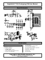
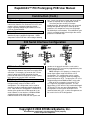
Rapid40iXL™ PIC Prototyping PCB User Manual
Copyright © 2004 DH MicroSystems, Inc.
All trademarks mentioned in this document are the property
of their respective companies.
Rapid40iXL™ PIC Prototyping PCB User Manual
Description
This is a PCB designed to facilitate the rapid
prototyping of a device based on a 40 pin Microchip
PIC microcontroller.
To allow users to focus on their application, we
take care of key housekeeping tasks associated with
a microcontroller-based device. To this end, our
PCB features several power supply options, a 40 pin
footprint for the microcontroller, and several
oscillator options.
Users can construct their application circuit in
our generous a generous prototyping area with
space available for several IC’s and /or numerous
discrete components.
Like our Rapid40i prototyping board, the
Rapid40iXL board has common I/O components; it
has the same 4 push buttons, 4 LEDs, and a buzzer.
It also has a RS232 interface that can be jumper
configured for DCE configuration for attachment to a
PC, or as DTE for attachment to another prototyping
board (no null modem cables required). See last
page of this document for detailed serial interface
information.
This board is constructed as a 2-layer throughhole board with clearly marked components on its
silkscreen layer, and ample space between
components so population of the board can be done
by anyone with basic soldering skills.
Additional Resources
Numerous sources of information are available
for both beginning and advanced users.
Microchip Technology Inc. manufactures the PIC
microcontroller line. Their website can be found at
www.microchip.com. It contains datasheets for all
of their microcontrollers, app-notes, and code
samples for a variety of applications.
Another excellent on-line resource for Microchip
PIC development is the Piclist at www.piclist.com.
It contains project info, code examples, and links to
PIC related sites.
Beginner users might also consider the books
published by Square 1 Electronics. They can be
found at www.sq-1.com.
This list is by no means comprehensive. Many
other excellent websites and publications are
available and this list is only intended as a starting
point for the beginner.
Features
General:
•
•
•
•
•
•
•
Overall board dimensions 4.00” x 4.00”.
PCB is a 2-layer board with solder masks on both
sides and a silk screen graphic.
36 x 14 pin prototyping area (504 pins total).
Power and GND bus lines run the length of the
prototyping area on both sides .
All 33 microcontroller port pins and ~MCLR pin
brought out to a clearly labeled strip along the top
of the prototyping area.
ICSP header.
4 corner mounting holes.
Microprocessor:
•
•
Compatible with all MicroChip PIC 40 pin DIP
packaged microprocessors.
PIC16C64, 65, 662, 67, 74, 765, 77, 774, 620,
PIC16F74, 77, 871, 874, 877,
PIC18C442, 452,
PIC18F442, 452, 448, 458 (and others).
Oscillator Options:
•
•
•
Crystal or ceramic resonator with external
capacitors (DC-20MHz).
Ceramic resonator with internal capacitors (DC20MHz).
RC oscillator.
Power Supply Options:
•
•
•
Footprints provided for either TO-92 or TO-220
voltage regulators.
Footprint provided for DC power receptacle.
Power-on LED.
User I/O Options:
•
•
•
•
4 push buttons.
4 LEDs.
Piezo buzzer.
RS232 interface.
Requirements
In order to assemble and use this board, a
user needs to have basic electronic tools and some
skill in their usage, and an 40 pin PIC microcontroller
and the tools required to write code and program the
executable file onto the controller. Additionally, if this
board was purchased as a bare PCB, then a number
of discrete components are also required to stock it.
Copyright © 2004 DH MicroSystems, Inc.
All trademarks mentioned in this document are the property
of their respective companies.
Rapid40iXL™ PIC Prototyping PCB User Manual
Board Schematic
Construction
Partlist:
If you purchased this as a kit, then it included
the following components:
• Printed circuit board
• IC1-40 pin socket
• X1-4MHz ceramic resonator
• VREG1-78L05 voltage regulator (TO-92)
• DC power JU1-ICSP header
•
•
•
•
•
•
•
•
JU2-ICSP header
JU3-Jumper block with shorting jumper
C1-47uF electrolytic capacitor
C2, C4, C5,C8, C9, & C15-0.1uF capacitors
R1-470 Ohm, 1/8W, resistor
R3-10k Ohm, 1/8W, resistor
D1-Green LED
D2-1N4148 diode
Copyright © 2004 DH MicroSystems, Inc.
All trademarks mentioned in this document are the property
of their respective companies.
Rapid40iXL™ PIC Prototyping PCB User Manual
Construction (Cont.)
Partlist (cont.):
If it was purchased as a kit including parts to
complete the user I/O circuitry then it also included:
• SW1 - SW4-tactile push-button switches
• LED1 - LED2-red (x2) and yellow (x2) LEDs
• BUZZ-5V piezo buzzer
• Q1-2N2222 (TO-92) NPN transistor
• R4, & R9 - R12-10k Ohm, 1/8W, resistors
• R5 – R8-470 Ohm, 1/8W, resistors
If purchased as a kit including parts to complete
the RS232 interface then it also includes:
• IC2-232 driver IC and 16 pin socket
• DB9F connector
• JU1-2x5 pin header & 4 shorting jumpers
• C9 to C13-0.1uF capacitors
• C14-47uF electrolytic capacitor
Note: parts are not provided to fill all PCB footprints.
The user should stock the board appropriately
according to the requirements of any particular
design (see construction options discussed below).
Microcontroller Options:
This board will support any 40 pin DIP packaged
Microchip PIC microcontroller. The pin descriptions
depicted in the schematic on the previous page and
on our PCBs represent only basic port definitions for
each pin. Refer to the Microchip datasheet for all
the features and alternate pin definitions for the
microcontroller that you select for use.
R3, C8, and D2 are attached to the ~MCLR pin
(D2 is added for ICSP compatibility). These
components can be omitted and a new reset circuit
can be constructed in the prototyping area per
instructions found in the Microchip datasheet for
your microcontroller.
ICSP:
Note: refer to Microchip datasheets and appnotes
for information on the isolation of ICSP related pins.
ICSP signals are available on JU2 (refer to the
schematic for pin signal assignments). Depending
on what PIC is selected for use the PGM pin may be
RB3 or RB5; to configure for either short either (not
both) position 3 or 5 on the jumper labeled PGM with
a short length of component lead left over from the
construction of this board. Refer to the Microchip
datasheet for the PIC you select for the assignment
of the PGM pin.
JU3 isolates the PIC from the boards power
supply; it should be disconnected when the
prototyping board is attached to an ICSP
programmer. This jumper eliminates the possibility
of excessive loading of the ICSP programmer by
other board components or by the users application
circuitry. Re-jumper JU3 when the ICSP
programmer is disconnected and the board is to be
powered via the onboard power supply.
If you are not planning on using an ICSP
programmer JU2 can be omitted, JU3 can just be
permanently shorted with a bit of component lead,
and D2 can be replaced with another bit of
component lead.
Oscillator Options:
Several oscillator options are available with this
board: ceramic resonator, crystal oscillator, and RC
oscillator (kits ship with a 4MHZ ceramic resonator).
Pertinent oscillator parts are R2, C6, C7, and X1.
Select these components per instructions found in
Microchip datasheets for the microcontroller that you
select for use.
Power Supply Options:
This board will support several different voltage
regulators in both TO-92 and TO-220 packages (kits
ship with a TO-92 78L05) Note: install only one
voltage regulator when assembling your board.
Keep in mind the current requirements of your
circuitry plus the microcontroller when you are
selecting an appropriate voltage regulator.
Depending on the requirements for the regulator
you select, C1, C2, C3, and C4 may or may not be
required and their values will vary. Refer to the
manufacturers datasheet for your regulator you
select for recommendations.
A wall adapter can provide power when the DC
power receptacle is installed. A 2.1mm ID, 5MM
OD DC power plug with a positive center conductor
is required. A bench supply can also be used; in
this case omit the power receptacle and solder in
red and black wires to the pins labeled Vin and GND
respectively. Voltage should be 7.5-12VDC.
A power-on LED may be installed by stocking R1
and D1 (a green LED).
Copyright © 2004 DH MicroSystems, Inc.
All trademarks mentioned in this document are the property
of their respective companies.
Rapid40iXL™ PIC Prototyping PCB User Manual
Construction (Cont.)
232 Interface Options:
This board offers a jumper-configurable 232
interface to allow the user to connect it to a PC or to
another similarly equipped prototyping board.
Details regarding configuring this board as DTE or
DCE can be found below.
Assembly:
Stock parts in their appropriate locations, paying
attention to proper component alignment. Solder
components to the PCB with a low wattage soldering
iron. Lastly, trim off excess leads and clean off flux
residue (if required) with an appropriate solvent.
Construct your own circuitry in the open
prototyping area. Microcontroller pins are accessed
through the labeled strip of pins at the top of the
proto area; I/O components are accessed through
the labeled pins at the bottom. 5V and GND for your
circuit is available on both left and right sides of the
proto area in labeled strips.
232 Serial Interface Configuration
232 Interface Notes:
Note: the arrows in the above figure denote the
signal direction between the processor and the DB9
connector. For example, the arrow on the TxD line
shows it going to the DB9F connector from the
processor; the arrow on the RxD line shows it going
to the processor from the DB9F connector.
JU1 Jumper Settings:
DTE: Setting the JU1 jumpers as shown in the
left figure above setups the DB9 in a DTE
configuration. This configuration can be used to
connect to another prototyping board configured as
DCE. Note: while this configuration is labeled DTE,
obviously the gender of the DB9 connector is not
male. However, if one attaches a DB9M to DB9M
straight-through wired serial cable to the
DB9Fconnector on the PCB, then the signals and
gender on the opposite end of the serial cable is
appropriate for DTE and can be plugged directly into
a DCE configured board.
DCE: Setting the JU1 jumpers as shown in the
center figure above setups the DB9 in a DCE
configuration. This configuration can be used to
connect to a PC serial port or another prototyping
board configured as DTE. To connect to a PC use a
straight-through wired DB9M to DB9F serial cable.
Both of the first examples have active RTS &
CTS signals for half-duplex operation. The last
figure above is DCE which is fully handshake looped
(RTS and CTS lines are now shorted together). This
configuration can be used for full-duplex serial
communication with a PC; a similar arrangement can
be used in the first DTE configuration.
Copyright © 2004 DH MicroSystems, Inc.
All trademarks mentioned in this document are the property
of their respective companies.
Rapid40iXL™ PIC Prototyping PCB User Manual
Notes
Contact Us
We maintain a website where you can get
information on our products, obtain literature, and
download support files. Visit us online at:
www.dhmicro.com
Email your technical support questions to
[email protected]. We try to respond to your
questions within an hour if it is received Monday
through Friday between the hours of 8am to 5pm
(Mountain Time).
For sales questions or to place an order, direct
your emails to [email protected]. Refer to the
order form and price list available on our website for
product pricing, shipping rates, payment instructions,
and for other info we need to complete your order.
Our mailing address:
DH MicroSystems, Inc.
P.O. Box 2272
Pocatello, ID 83206-2272
Disclaimer: DH MicroSystems, Inc. reserves the right to modify its products or literature, or to
discontinue any product at any time without prior notice. The customer is responsible for determining
the suitability of any device for any application developed using DH MicroSystems, Inc. components.
Copyright © 2004 DH MicroSystems, Inc.
All trademarks mentioned in this document are the property
of their respective companies.