1
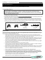
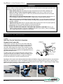
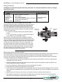
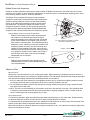
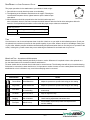
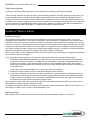
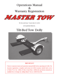
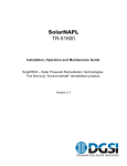
User Manual
Models GW 1125 & GW 1125-GL
GearWagon™ 125 Sport Utility & Performance Trailer™
GearWagon™ 125 Camper
Read this owner’s manual carefully before
you begin using your Trailer.
Safe Use & Operation
pg. 3
GearWagon 125 Specifications pg. 4
GearWagon 125 Camper
Features & Operation
pg. 6
Inspection, Maintenance and Cleaning
pg.12
Trailer Licensing
pg.16
Warranty / Repair Procedures
pg.16
Save This Manual
Read the owner’s manual over carefully before you begin using your trailer. You will need
this manual for the safety warnings and precautions, operating procedures, parts list,
inspection, and maintenance information. Keep this manual for continued reference.
Copyright © 2007 - 2012 Let’s Go Aero, Inc.
GearWagon™ 125 Sport Performance Trailer
Safe Use & Operation
Be sure to follow these guidelines to prevent possible hazards from misuse.
Important Safety Check List
1.Do NOT exceed the trailer’s maximum weight capacity load of 1,000 lbs (455 kilos) The Gross Vehicle Weight
Rating (G.V.W.R.) for the GearWagon™ 125 trailer is 1,480 lbs (672 kilos), and is calculated as follows:
The Empty Weight of the Trailer (480 lbs/218 kilos) + the maximum payload the trailer can carry (1,000 lbs/455
kilos) = 1,480 lbs/672 Kilograms G.V.W.R.
2.Make sure the towing vehicle as well as the hitch is capable of towing the trailer and its payload. Check your vehicle
and hitch owner’s manual for tow ratings.
3.The tail light bulbs supplied with this trailer are for a 12 volt DC electrical system only. Do not attempt to power the light
bulbs with any other type or voltage electrical current.
4.Always check to make sure the payload being transported is properly and safely secured in the trailer. Never placeloads on one side only. Load the trailer evenly from side to side with 60% of the load forward of the axle (the tongue
weight is 10% of the load, which does not include the wieght of the trailer. The load is divided so that 90% of the load
is over the axle and 10% is over the tongue). See diagrams below:
Center Load from
Side to Side
60% of Load
Forward of Axle
90% of Load
Over Axle
Before Each Use
Trailers are generally not used everyday. Your trailer may sit for extended periods of time between uses making it very important to check all components thoroughly before each use. Following these simple instructions will maximize the life of your
trailer and keep you safely transporting your cargo.
•
•
•
•
•
•
•
•
•
•
•
Always check wheel lug nuts for proper tightness. When using trailer for the first time, check wheel lug nuts for
proper tightness at 50 miles of travel. Before every subsequent use and at 500 mile intervals during every trip, check
and tighten the tire lug nuts. Always ensure wheel bolts are tight. Torque to 50 – 75 ft.-lbs.
Inspect the general condition of the trailer. Check for loose bolts and nuts, misalignment or binding of moving parts,
cracked, bent, or broken parts, excessively worn safety cable, damaged tail lights/side running lights/wire harness,
loose lug nuts, loose hitch connection, and any other condition that may affect its safe operation.
Check your maintenance schedule to ensure that all routine maintenance matters are current. Perform any neglected maintenance by a qualified technician.
Check the tires for wear and the tire pressure for proper inflation (30 PSI).
Check the operation of all lights. Replace any faulty bulbs. Operating lights are mandatory on a trailer. Periodically
check lighting when towing over long distances. Check the tightness of all connections.
Make sure wiring is properly installed and secured to trailer to prevent from hanging and catching on any road debris.
Make sure the safety cables are attached to the trailer and the towing vehicle. Criss-cross cables as necessary to
prevent from hanging and catching on any road debris.
Check and adjust your tow vehicle’s tow height to make sure that the trailer is being towed level.
Check that the trailer coupler is fastened securely onto the trailer ball. The GearWagon™ 125 is equipped with a
2” coupler and must be used with a 2” trailer ball. After assembly and attachment, pull up and down on the coupler
to make sure the hitch ball is fitting snugly in the coupler. If the coupler is not secured properly, the ball could come
loose while the trailer is in motion, possibly causing property damage, serious personal injury, or death.
Verify that endgate is secured by properly closing draw latch.
Verify that the lid is secured using elastomer draw latch and pin locks furnished.
GW 1125-9/12
––
GearWagon™ 125 Sport Performance Trailer
WARNINGS
Failure to adhere to these recommendations may result in potential hazards from improper operation, including property damage and bodily injury.
• Keep children away. Be sure children are kept a safe distance from the trailer operating area.
• Never sit, stand, or ride on the trailer (people or pets). Serious injury or death could occur.
• Whenever possible, park the trailer on a flat, level, paved surface and chock both tires to keep the
trailer from accidently moving.
• When driving do not exceed the speed limit. Braking time can be considerably longer when a vehicle is towing a loaded trailer. Excess speed is a major cause of vehicle-trailer accidents.
• Make sure the coupler is secured properly to the hitch ball. If not secured properly, the ball could
come loose while the trailer is in motion, possibly causing property damage, SERIOUS PERSONAL
INJURY, or DEATH.
• Tighten wheel lug nuts. Failure to properly tighten wheel lug nuts and to check for proper tightness
during travel my result in property damage or serious personal injury.
• Secure lids using elastomer draw latches and pin locks furnished.
• DO NOT EXCEED YOUR VEHICLE’S TOW LIMITS OR TRAILER’S LOAD LIMIT. Refer to your
vehicle’s towing information to learn the capabilities and limits of your vehicle. Refer to GearWagon
125’s weight specifications on page 3 for load details.
GearWagon 125’s Specifications
Coupler
Make Sure That the Trailer Ball is Completely
Engaged in the Coupler Ball
Place coupler over the 2” trailer ball on your vehicle. Raise the
locking lever to allow the coupler to drop fully onto the hitch ball.
Press the locking lever down on the coupler to make sure the
hitch ball is fitting snugly in the coupler. There should be no play
between the hitch ball and the coupler. If there is play, tighten the
adjustment nut until no play is present. If the adjustment nut is too
tight, the handle will not lock.
To adjust coupler to ball, raise the locking lever, push up on the
channel lock and turn nut to tighten or loosen the coupler. Proper
adjustment is obtained when coupler is as tight as possible on
the ball and locking lever can still be opened and closed.
Locking Handle
(Position B)
2" Ball Only Not Included
Locking Handle
(Position A)
2" Trailer
Coupler
Channel Lock
Adjustment Nut
GearWagon 125’s coupler comes with the Handi-Grip handle and Stabilizer swing arm stand with caster for easy maneuverability when uncoupled from the vehicle. The Stabilizer swing arm secures in reclined position for transit. Pull arm away to
release from notched position in order to operate in downward position for trailer support. To adjust swing arm height, simply
adjust arm length by pressing the release latch on the arm.
GW 1125-9/12
––
GearWagon™ 125 Sport Performance Trailer
Weight and Load Ratings
The Gross Vehicle Weight Rating (G.V.W.R.) for the GearWagon™ 125 trailer is 1,480 lbs (672 kilos), and is calculated
as follows:
The Empty Weight of the Trailer (480 lbs/218 kilos) + the maximum payload the trailer can carry (1,000 lbs/455 kilos)
=1,480 lbs/672 Kilograms G.V.W.R.
Hitch, Ball, Wire Plug
GearWagon 125’s can be pulled with any tow rated vehicle and receiver (Class I on up). Never exceed your vehicle’s tow
limit, as specified by your vehicle and hitch manufacturer’s rating. See page 3 for trailer weight and load ratings.
The optimal ball height is 17 inches from the ground. Coupling the trailer at the
designed height will insure that the trailer floor is level in orientation to the ground.
The GearWagon 125’s coupler fits a 2” size ball. Make sure that the ball used is
matching in size and is rated equal to or greater than the towing load.
GearWagon 125 uses a four-flat connector plug. Vehicles with a round pin plug should source a wire plug adaptor.
Lid and Endgate Operation
Opening and Closing
Use the lid handle for opening and closing tonneau style lid.
Release the gas shock by pressing in when closing lid
(GearWagon 125 Camper model). Rotate draw latches
inside trailer to open and close endgate. The endgate
may fold to the ground by releasing the cable carabiners.
Endgate Weight Rating
The endgate supports 400 lbs of weight for sitting. It is not designed
for load bearing weight as a ramp. For heavy wheel items like ATVs, a ramp should be used.
Securing Trailer for Transit
For security, two Locks with a sets of keys are included. To apply locks, first
close Lid and secure Lid Latch. Remove lock from pin and insert pin through
hole located at the lip where lid and base overlays. Apply Lock by inserting into
pin (we recommend applying lock above the lid as shown in photo).
At a notched location, turn key counter clockwise to lock; turn key clockwise to
unlock. Be sure that lock is engaged after removing key (pull on lock).
WARNING
Lock down lids using either one or both pin locks
before transit. Failure to do so may result in property
damage under extreme road or weather conditions.
GW 1125-9/12
––
GearWagon™ 125 Sport Performance Trailer
Use of C-Channel Track Inside Trailer Base
The C-Channel Track provides attachment point capability, using things like bungee cords and ratchet straps.
Let’s Go Aero offers Tie Down hardware that is custom fit for use in the track. Consult your local dealer for
accessories, or contact Let’s Go Aero.
Painting your Trailer
The GearWagon 125 trailer uses a twin walled base made of high density polyethylene, and ABS lids. The ABS lid is paintable; the polyethylene base is not. Consult a local vehicle paint shop for services. To prepare for painting, simply wash the
lid with a mild dish soap and rinse.
Fenders
WARNING
Do NOT stand on fenders! Standing on
fenders is a misuse of product, may result in
property damage, and will void the warranty.
GearWagon™ 125 Camper Features (Model No. GW1125-GL)
The GearWagon 125 Camper model integrates the following features into the GearWagon 125 Trailer:
• Leveler Kit
Two height adjustable and retractable stabilizer jacks secure underneath trailer for use when off the hitch.
Prevents rearward tipping when standing in trailer or sitting on endgate (when trailer is uncoupled from the hitch).
• Decking
Modular, four panel decking provides added level for sleeping and/or storage and organization of cargo. Stores
along trailer sidewalls for transport when not in use, allowing complete access of trailer’s capacity for cargo transport when stores.
• Tent & Vestibule
Trailer enclosure with added shelter over endgate. Quick and easy set up; stores in two small tent like sacs for
complete use of trailer’s capacity for cargo transport when not used for sleeping.
• SolarVent
Solar powered ventilator removes condensation from accumulating during the night and provides quiet, reliable
ventilation. Moves 1,000 cubic feet per hour, will run for up to 48 hours without sunlight. Also prevents mold and
mildews.
GW 1125-9/12
––
GearWagon™ 125 Sport Performance Trailer
Leveler Kit
The Leveler Kit is an integrated feature of the GearWagon
125 Camping Trailer for stabilization of the trailer when
removed from the vehicle’s hitch.
Operation
• To extend legs, pull leg outward to release the spring catch and detent
lance. Allow the leg to swing downward until the lance engages in the
extended slot position.
• To retract legs, first minimize the leg length to the shortest position, then
pull leg downward to release the lance from its extended and locked
position. Swing the leg upward into the retracted position until the lance
catches in the retracted slot. Before driving, verify that the legs are retracted
and that the locking lance is fully engaged in the locking slot.
Vertical
and
horizontal
catch
positions
Height
adjustment
lever
To release from catch position, pull leveler forward (toward front of
trailer).
Swing leveler down.
Adjust height by pressing downward on adjustment lever.
To prepare for transit, release adjustment lever to minimize leg
length and fold upward to retracted, catched position shown
above.
WARNING: Always fold up Leveler Kit in secure position before operating trailer.
Do not move trailer with stabilizers down, or damage will occur.
GW 1125-9/12
––
GearWagon™ 125 Sport Performance Trailer
Decking: Storage & Installation
Decking consists of four panels that are design-fit for position
along the base interior’s molded ledging.
Modular design for compact storage. Two panels store on
each side of trailer as shown.
Storage
Storage
Eachpanel
panelisisaadifferent
differentlength,
length,and
andisisnumbered
numbered
1
Each
1 through
4.
through
4. and
For access,
best fit and
access,
follow thedescribed
positioning
For
best fit
follow
the positioning
below:
described below:
Panels #1 and #2 store on driver side. Store panel 2, followed
Panels
and
#2 store
on driver
side. Store
panel
1, folby
panel #1
1 (so
panel
1 is most
accessible).
Note how
panel
one’s
lowed
by
panel
2.
Note
how
panel
two’s
steel
channel
rests
steel channel rests above panel 2 as shown.
above panel one as shown.
Panels #3 and #4 store on passenger side. Store panel 4, followed
Panel
#4 store
on passenger
side.
Store
by
panel#33 and
(so panel
3 is most
accessible).
Note
how panel
panel 3,
three’s
followed
by
panel
4.
Note
how
panel
four’s
steel
channel
steel channel rests above panel 4 as shown.
rests above panel three as shown.
The decking’s galvanized channel should face the sidewall
The decking’s galvanized channel should face the
of
the trailer
and
rest
on therest
molded
deck
ledge with
inside
of thebase
trailer
and
should
on the
c channel
the
upper
panel’s
channel
resting
on
the
lower
panel’s
with the upper panel’s channel resting on the lower
channel.
Pull retainer
tightstrap
to prevent
from
panel’s channel.
Pullstrap
retainer
tight topanels
prevent
panels
shifting
in
transit.
from shifting in transit.
Installation
The decking panels position sequentially beginning at the front with
panel #1. Proceed as follows:
Loosen decking straps starting with panels 3 and 4 located on the passenger side. Move these two panels to the rear to make room for installation of panels 1 and 2.
Remove panels 1 and 2, then place them in their respective deck locations from the front of the trailer starting with panel 1.
Be sure to install correctly, as each panel’s length is designed for its specific location in the sequence.
GW 1125-9/12
––
GearWagon™ 125 Sport Performance Trailer
Tent & Vestibule Set Up
An integrated feature of the GearWagon 125 Camping Trailer. Tent and
Vestibule knock down and store in separate tent bags when not in use.
Parts List
Tent
Vestibule
Tubing for Vestibule
2 Side Tubes (one with End Fitting), 60” length
1 Arc Tube (with End Fitting)
1 Peak Tube, 30” length
Installation
Extend Leveler Kit. Open trailer lid and endgate.
Ensure lid’s gas lift lock is engaged (press to release when closing lid).
Tent
Open tent and locate its rear, upper center area. Starting from the
inside of trailer at lid center, attach tent velcro to the velcro on the inside
of the lid. Begin with the direction to the driver’s side, and route along lid.
Route tent to the outside of the tonneau lift in the process.
Repeat to the passenger’s side, routing tent wrap to the outside of the HBar in the process (this portion of the tent will wrap around the outside of
the trailer’s base).
Connect outside bungee by connecting the two hooks located on each end of the tent wrap.
Finish velcro wrap inside and outside by overlaying the two velcro ends.
GW 1125-9/12
––
GearWagon™ 125 Sport Performance Trailer
Hook bungee clip to tailgate’s cable as shown. Repeat on both sides.
Button endgate snaps. There are two snaps along both vertical sides, and
five snaps on the inside of base. Insure bungee is under trailer’s base rim.
Vestibule
Open vestibule and remove tent poles. Begin attaching upper vestibule
zipper starting from the top corner of the driver’s side. Zip vestibule sides.
Install arc pole through vestibule sleeve located at
the top of vestibule doorway (slide the side without
the end fitting through the sleeve)
Starting with the arc tube side with end fitting, connect vestibule side tube
to arc tube. Insert end tip in corner of trailer base
as shown. Repeat step on both sides.
Snap vestibule side locations. There are two snaps
on the outside of both sides of the base. Connect
vestibule cover snaps located underneath lowered
endgate.
Connect peak tubes and insert into vestibule’s center
sleeve. Slip end through holder as shown (rubber end
for contact with lid).
GW 1125-9/12
– 10 –
GearWagon™ 125 Sport Performance Trailer
SolarVENT
Integrated in the GearWagon 125 Camping Trailer is the SolarVent, a solar powered ventilator for removing
condensation from accumulating during the night. While moving 1,000 cubic feet per hour, it will run for up to 48
hours without sunlight and prevents mold and mildews.
To operate, raise the vent fan and set to intake or exhaust. When driving in rain, be sure to close vent to prevent
water from entering.
Two AA batteries are included. If the vent is not working, the batteries may be dead and need replacement. To
maintain operation, remove the batteries (in this case the batteries can actually cause a short circuit and prevent
the energy from the solar panel from reaching the motor). Place the SolarVent in direct sunlight (the vent can
work without batteries, but will only ventilate during sunlight hours).
Consult SolarVent manual by ICP Solar Technologies furnished with your trailer for more information.
GW 1125-9/12
– 11 –
GearWagon™ 125 Sport Performance Trailer
Inspection, Maintenance, and Cleaning
All replacement parts, maintenance and repairs should be undertaken by certified and licensed technicians. The buyer
assumes all risk and liability arising out of his or her repairs to the original product or replacement parts, or arising out of
his or her installation of replacement parts.
•
•
•
•
Once a year or every 6,000 miles, inspect the bearings for proper lubrication. Repack if necessary. Be sure to
have a qualified technician re-pack the hub assembly and handle other maintenance items.
To reduce friction between the coupler and hitch ball, apply a layer of heavy weight grease over the hitch ball.
Lubrication of the coupler should be done periodically to stop corrosion and keep parts moving freely.
When servicing, use only identical replacement parts. Only use accessories intended for use with this product.
Any modifications made to the trailer or parts of the trailer will void the trailer warranty and release Let’s Go Aero
of any responsibility for damages, injuries, or accidents incurred.
Wiring
• The GearWagon™ 125 has a four flat-connector wire style plug. This is a common pin hole configuration for the
wiring of towables. Check to verify your vehicle’s wiring plug style. Should it differ, consult your local hitch installer
for a wire plug adaptor.
• Always check all lights before towing for brake, running, signal, and side marker light operation. Make sure that all
your connections are solid and that all wiring is in good condition. Should the brake, signal, or running lights not be
working, first check that the vehicle’s lighting is operating properly.
Note: Bare, striped or pinched wire will cause a short in the trailer, which will cause the vehicle fuse to blow. A solid
ground is required for your lights to work properly. All contacts must be to bare metal. Light covers should be
well maintained and kept clean. Be sure that your lights are always visible, not obstructed by your load.
To test vehicle wiring:
You will need a 12v light tester. Attach the wire clamp of the tester to the ground wire on the vehicle plug. Then
touch the tester pin into one of the vehicle plug contacts. Turn on the corresponding vehicle operation, i.e., running lights. This will illuminate the tester light if the vehicle wiring is correct. Follow this same procedure for the
signal and brake lights.
Bearing Inspection / Replacement
GearWagon 125’s axle bearings have been factory lubricated. The bearings should be inspected any time the hub
is removed from the axle or at intervals as outlined in the maintenance schedule shown on page 11 of this manual. The
bearing cones should show no signs of excessive wear or damage such as flat spots on the rollers, broken cages, pitting,
or corrosion. The bearing cups that are pressed into the hub should also be checked for wear or damage. If the bearings
do need to be replaced, follow the procedure as outlined and only use bearings that are approved for use in the following
chart.
IMPORTANT: Both the bearing cup and bearing cone should be replaced any time a bearing is replaced.
The following procedure should be used for bearing cup replacement:
1.Carefully tap the existing bearing cup out of the hub using a brass punch
2.Clean the bore area after removing the cup to ensure there are no nicks or burrs.
3.Carefully tap the new bearing cup into the hub making sure the cup is seated against the bottom of the bore.
Bearing Replacement & Interchange
Axle
Capacity
1000# - 2500#
GW 1125-9/12
# of
Bolts
Spindle
Type
4 or 5
Straight
Inner Bearings
Cup
Cone
L44610
L44643
Outer Bearings
Cup
Cone
L44610
– 12 –
L44643
GearWagon™ 125 Sport Performance Trailer
Bearing Lubrication
GearWagon 125’s axle bearings have been factory lubricated. For continued maintanance, below is a listing of
approved lubrication:
Lubrication Specifications
Grease
Soap Type
Consistency
Dropping Point
Additives
Base Oil
Viscosity Index
Lithium Complex or Equivalent
NLGI Grade 2
230°C (446°F) Minimum
Corrosion and Oxidation Inhibitors, EP Optical
Solvent refined petroleum oil
80 Minimum
The GearWagon trailer’s axle is equipped with the Sure Lube
greasing system which allows, the bearings to be lubricated without
the hassle of packing the bearings by hand. After assembling the
unit, simply apply grease through the grease fitting that is in the
end of the grease cap or spindle. The grease used should meet the
requirements as shown in the chart above. The following amounts
of grease should be used:
Approved Sources
Exxon Ronex MP or
equivalent
Sure Lube
Grease Cap
Hub
• 5-7 ounces to completely exchange the grease throughout
Sure Lube
Spindle
the hub
• 1 1/2 - 3 ounces every 12 months or 6,000 miles thereafter or
as use requires (ie, if submerged in water).
With the Sure Lube System the grease is pumped through the
hub via the grease zerk located in the end of the grease cap. The
grease is forced through the bearings and out of the exit hole ahead
of the seal. The old grease that is inside of the hub is forced out of
the hub cavity and exits though the rear hole on the spindle. You
can visibly tell when the old grease is flushed out when you see a
steady flow of the new grease coming from the rear of the spindle
(with exception to the straight style of axles). The grease can then
be wiped from the rear of the spindle or, in the case of a straight
axle, the grease will flow inside of the axle tube.
Bearing Adjustment and Hub Installation
Bearing adjustment is a very important part of achieving maximum bearing life and trouble-free service. Most bearing failures can be attributed to improper bearing adjustment, normally due to the bearings being adjusted too tight.
Once all of the necessary inspections have been performed and the units have been properly lubricated, the following
procedure should be used for reinstallation of the hubs:
1. Place the lubricated unit onto the same spindle from which it was removed. Make sure all of the components are
reinstalled as they were removed.
2. Tighten the spindle nut to 30-40 ft./lbs. while turning the hub to ensure the bearings are properly seated. Do not
move the hub after this step is completed.
3. Loosen the spindle nut completely until the nut can be turned with your fingers.
4. Finger-tighten the spindle nut by hand without moving the hub.
5. If the cotter pin can be assembled with the nut finger-tight, insert the cotter pin without backing the nut off. If the cotter pin cannot be assembled with the nut finger-tight, back the spindle nut up to the next available slot and insert the
cotter pin.
6. Bend the legs of the cotter pin over the top of the spindle to ensure the spindle nut will not back off.
7. The spindle nut should be free to move with your fingers with only the cotter pin holding it in place and the hub
should not have noticeable movement when pulled back and forth.
GW 1125-9/12
– 13 –
GearWagon™ 125 Sport Performance Trailer
Rubber Torsion Axle Suspension
Except for periodic inspection of the fasteners used to attach the Rubber Torsion axle to the trailer frame and a visual
inspection of the welds, no other suspension maintenance is required. However, all maintenance regarding hubs, drums,
rotors, bearing, wheels, and tires, should be adhered to.
The Rubber Torsion Suspension System is a self-contained
suspension system that is housed entirely inside the axle beam.
Unlike the spring suspension system, the axle beam attaches
directly to the trailer frame without the need for various mounting components. The action provided by the Rubber Torsion
Suspension System is unique from the leaf spring suspension
providing several operating advantages including independent
suspension and a virtually maintenance-free suspension system.
How the Rubber Torsion Suspension System Works
Rubber Torsion Axles provide a much improved trailer
ride relative to conventional spring axles through a
unique arrangement of the steel torsion bar surrounded
by four natural rubber cords encased in the main structural member of the axle beam. The wheel/hub spindle is
attached to a lever, called the torsion arm assembly. This
assembly includes the torsion arm, the torsion bar and
spindle. As load is applied to the trailer, the torsion arm
assembly pivots around the torsion bar, causing a rolling
or compressive resistance in the rubber cords inside of
the axle beam. Both sides of the axle are completely
independent from one another.
As Load is Applied to the Trailer, the Torsion
Arm Moves to Absorb the Shock
Direction of Travel
Front of
Trailer
Direction of Travel
Rubber Torsion axle beams and stub axles must be
mounted with the torsion arm and spindle trailing to the
rear of the axle beam.
Wheels and Tires
Wheel Selection
Wheels are a critical component of your running gear system. When specifying or replacing your trailer wheels it is
important that the wheels, tires, and axle are properly matched. The following characteristics are extremely important
and should be thoroughly checked when replacement wheels are considered.
1.Bolt Circle. Many bolt circle dimensions are available and some vary by so little that it might be possible to attach
an improper wheel that does not match the hub. Be sure to match you wheel to the hub.
2.Capacity. Make sure that the wheels have enough load carrying capacity and pressure rating to match the maximum load of the tire and trailer.
3.Offset. This refers to the relationship of the centerline of the tire to the hub face of the axle. Care should be taken
to match any replacement wheel with the same offset wheel as originally equipped. Failure to match offset can
result in reducing the load carrying capacity of your axle.
Torque Requirements
It is extremely important to apply and maintain proper wheel mounting torque on your trailer axle. Torque wrenches
are the best method to ensure the proper amount of torque is being applied to a fastener.
It is important that the specified torque levels are maintained on the wheel nuts or bolts on your axle to prevent loose
wheels, broken wheel studs, and possible wheel separation from the axle.
Wheel nuts and bolts are offered in different cone angles (usually 60° or 90°). It is important to match the angle of the
fastener to the wheel on the axle.
GW 1125-9/12
– 14 –
GearWagon™ 125 Sport Performance Trailer
The proper procedure for the attachment of your wheels is listed at right.
4
1.Start all bolts or nuts by hand to prevent cross threading.
1
2.The tightening of the fasteners should be done in stages. Following the 2
recommended sequence above, tighten fasteners per the wheel torque chart below.
5
3
5 Bolt Pattern
3.Wheel fasteners should be torqued before the first initial road usage and after each wheel removal. Check and retorque the wheel fasteners after the first 50 miles and again at 500 mile
intervals. Check periodically thereafter to ensure that the proper torque values are maintained.
Wheel Torque Values
Wheel Size
13"
1st Stage
2nd Stage
3rd Stage
20-25 ft./lbs.
35-40 ft./lbs.
60-75 ft./lbs.
Tires
Like the tires on a car, the most important factor in the life of the tires on your trailer is their inflation pressure. Check your
tire placard for the amount of pressure for the specific capacity of your trailer. Inflate to 30 psi for GearWagon. During use
of your trailer, inflation pressure should be checked weekly and performed when the tires are cold (prior to operation of the
trailer). In doing this, you will ensure that you are achieving the maximum life and tread wear for your tires.
Wheels and Tires – Inspection and Maintenance
Wheels should be visually checked periodically for dents or cracks. Whenever it is required to have a tire replaced on a
rim, the wheel needs to be checked for balance and distortion.
Tire wear should also be checked often for abnormal or excessive wear. The following chart will aid you in troubleshooting
if abnormal or excessive tire wear should occur. It is important to monitor tire wear, as once a wear pattern becomes firmly
established in a tire it is difficult to stop, even if the underlying cause is corrected.
Tire Wear Diagnostic Chart
Wear Pattern
Cause
Action
Center Wear
Overinflated tire
Adjust tire pressure to specific load rating per tire catalog
Edge Wear
Underinflated tire
Adjust tire pressure to specific load rating per tire catalog
Side Wear
Loss of camber
or overloading
Make sure load does not exceed axle rating. Realign axle
at axle shop
Toe Wear
Incorrect toe-in
Align at alignment shop
Cupping
Out-of-balance
Check bearing adjustment and balance tires
Flat Spots
Wheel lockup
GW 1125-9/12
Avoid sudden stops when possible and adjust brakes
and tire skidding
– 15 –
GearWagon™ 125 Sport Performance Trailer
Maintenance Schedule
Below is a maintenance schedule for routine maintenance of your trailer.
500 Mile
Item
Function
Required
Intervals
Hub/Drum/Rotor
3 Months
or
1000 Miles
6 Months
or
3000 Miles
Inspect for
abnormal wear
Bearings (Sure Lube- Replenish grease
Bearing Lube)
in the system
Seals
Inspect for leakage
Replace if worn
Wheel Nuts and Bolts
Check torque
values
12 Months
or
6,000 Miles
•
•
•
Refer to
Page
•
Rubber Torsion Axles
With The Suspension Built-In
• A Soft, Quiet, No Shock Ride With
Independent Wheel Action.
• Load Carrying Crossmember.
• Maintenance Free.
• Eliminates Sway.
FEATURES
BENEFITS
Progressive Torque
Simple Design
Added Strength
Increases Carrying Capacity as Load is Applied
Gives a Good Ride Whether Unloaded or Loaded to Capacity
Control and Stability
Reduced Oscillation (Self Dampening)
Variety of Capacities, Track and Mounting Widths
Excellent Ground Clearance
No Shock Absorbers; Special Compound Rubber has a Natural Dampening Characteristic
No Metal to Metal Contact - Eliminates Need for Lubrication
Helps Strengthen the Frame of the Chassis
Possible to Reduce the Size of the Main Frame Members )Reduces Cost and Weight)
Retards Frame Twisting
Assured Proper Fit Eliminates Down Time and Rework/Repair
High Quality Standards
Outstanding Quality Control of Components Reduces Maintenance and Repair
GW 1125-9/12
– 16 –
––
13
––
14
GearWagon™ 125 Sport Performance Trailer
Trailer Licensing Notice
Consult your vehicle licensing department for towing requirements relating to licensing and registration.
In the US, some states may consider this trailer a vehicle requiring registration, licensing, and titling. In many states, you
will need the Manufacturers Certificate of Origin filled out and signed by the dealer transferring ownership to you (the
reseller from whom you purchased the trailer). Take this M.C.O. along with your bill of sale (cash register receipt) to your
local DMV. Once you pay the appropriate fees, you will be issued a title or registration and license plate. Some states may
require inspection of the assembled trailer before issuing a title, registration, or license. Check with your Department of
Motor Vehicles for information and guidance on registering, licensing, and titling the trailer.
GearWagon™ Warranty & Repair
Let’s Go Aero offers a 1 year limited warranty to each new Let’s Go Aero trailer against manufacturing defects in workmanship and materials.
The obligation under this warranty is limited to the replacement or repair at the manufacturer’s factory, or at a point
designated by the manufacturer, of such part as shall appear to the manufacturer or manufacturer’s representative upon
inspection of such part to have been defective in material or workmanship. This warranty does not obligate Let’s Go Aero
to bear the cost of labor or transportation charges in connection with the replacement or repair of defective parts, nor shall
it apply to a product upon which alterations have been made or for equipment misused, neglected or improperly installed.
Let’s Go Aero reserves the right to improve any product through changes in design or materials as it may deem desirable
without being obligated to incorporate such changes in products of previous manufacture.
Bills for service, labor, or other expenses which have been incurred by the buyer without express approval or authorization
by Let’s Go Aero will not be accepted.
If your trailer fails to operate properly, or fails within the warranty period, the following steps should be taken:
1. An RMA (Return Merchandise Authorization) is required for any return of product for warranty work of defective
components. Contact Let’s Go Aero for an RMA, phone 719-630-3800, or via email to [email protected].
Freight must be prepaid – collect shipments will be refused. Include your RMA number, name, return address,
phone number and a description of the problem. A copy of the receipt including date of purchase is necessary for
any warranty claim.
If your trailer was purchased outside the U.S., consult your dealer for assistance.
2. If damages are due to abuse or misuse, owner will be charged for parts and labor.
3. If any of the components of your trailer are found to be faulty due to defective material or workmanship, they will
be repaired at no charge and returned with transportation charges prepaid. If failure occurred because of abuse,
neglect or misuse, an estimate of cost to repair will be submitted back to the owner. After repairs are completed,
the material will be returned with transportation charges collect.
Any modifications made to the trailer or parts of the trailer will void the trailer warranty and release Let’s Go Aero of any
responsibility for damages, injuries or accidents incurred.
For further information and customer assistance, call 719-630-3800, write to Let’s Go Aero, 3380 N El Paso Street, Colorado Springs, CO 80907, USA, or email to [email protected].
Replacement Parts
Parts replacements from wear and tear may be sourced through your GearWagon dealer or Let’s Go Aero.
GW 1125-9/12
– 17 –