1
GPIB-130
User Manual
November 1993 Edition
Part Number 370897A-01
© Copyright 1991, 1994 National Instruments Corporation.
All Rights Reserved.
National Instruments Corporate Headquarters
6504 Bridge Point Parkway
Austin, TX 78730-5039
(512) 794-0100
Technical support fax: (800) 328-2203
(512) 794-5678
Branch Offices:
Australia (03) 879 9422, Austria (0662) 435986, Belgium 02/757.00.20, Canada (Ontario) (519) 622-9310,
Canada (Québec) (514) 694-8521, Denmark 45 76 26 00, Finland (90) 527 2321, France (1) 48 14 24 24,
Germany 089/741 31 30, Italy 02/48301892, Japan (03) 3788-1921, Netherlands 03480-33466, Norway 32-848400,
Spain (91) 640 0085, Sweden 08-730 49 70, Switzerland 056/20 51 51, U.K. 0635 523545
Limited Warranty
The GPIB-130 is warranted against defects in materials and workmanship for a period of two years from the date of
shipment, as evidenced by receipts or other documentation. National Instruments will, at its option, repair or replace
equipment that proves to be defective during the warranty period. This warranty includes parts and labor.
A Return Material Authorization (RMA) number must be obtained from the factory and clearly marked on the
outside of the package before any equipment will be accepted for warranty work. National Instruments will pay the
shipping costs of returning to the owner parts which are covered by warranty.
National Instruments believes that the information in this manual is accurate. The document has been carefully
reviewed for technical accuracy. In the event that technical or typographical errors exist, National Instruments
reserves the right to make changes to subsequent editions of this document without prior notice to holders of this
edition. The reader should consult National Instruments if errors are suspected. In no event shall National
Instruments be liable for any damages arising out of or related to this document or the information contained in it.
EXCEPT AS SPECIFIED HEREIN, NATIONAL INSTRUMENTS MAKES NO WARRANTIES, EXPRESS OR IMPLIED ,
AND SPECIFICALLY DISCLAIMS ANY WARRANTY OF MERCHANTABILITY OR FITNESS FOR A PARTICULAR
PURPOSE . CUSTOMER ’S RIGHT TO RECOVER DAMAGES CAUSED BY FAULT OR NEGLIGENCE ON THE PART
OF NATIONAL INSTRUMENTS SHALL BE LIMITED TO THE AMOUNT THERETOFORE PAID BY THE CUSTOMER.
NATIONAL INSTRUMENTS WILL NOT BE LIABLE FOR DAMAGES RESULTING FROM LOSS OF DATA, PROFITS,
USE OF PRODUCTS, OR INCIDENTAL OR CONSEQUENTIAL DAMAGES , EVEN IF ADVISED OF THE POSSIBILITY
THEREOF. This limitation of the liability of National Instruments will apply regardless of the form of action,
whether in contract or tort, including negligence. Any action against National Instruments must be brought within
one year after the cause of action accrues. National Instruments shall not be liable for any delay in performance due
to causes beyond its reasonable control. The warranty provided herein does not cover damages, defects,
malfunctions, or service failures caused by owner’s failure to follow the National Instruments installation, operation,
or maintenance instructions; owner’s modification of the product; owner’s abuse, misuse, or negligent acts; and
power failure or surges, fire, flood, accident, actions of third parties, or other events outside reasonable control.
Copyright
Under the copyright laws, this publication may not be reproduced or transmitted in any form, electronic or
mechanical, including photocopying, recording, storing in an information retrieval system, or translating, in whole
or in part, without the prior written consent of National Instruments Corporation.
Trademarks
Product and company names listed are trademarks or trade names of their respective companies.
Warning Regarding Medical and Clinical Use
of National Instruments Products
National Instruments products are not designed with components and testing intended to ensure a level of reliability
suitable for use in treatment and diagnosis of humans. Applications of National Instruments products involving
medical or clinical treatment can create a potential for accidental injury caused by product failure, or by errors on
the part of the user or application designer. Any use or application of National Instruments products for or involving
medical or clinical treatment must be performed by properly trained and qualified medical personnel, and all
traditional medical safeguards, equipment, and procedures that are appropriate in the particular situation to prevent
serious injury or death should always continue to be used when National Instruments products are being used.
National Instruments products are NOT intended to be a substitute for any form of established process, procedure, or
equipment used to monitor or safeguard human health and safety in medical or clinical treatment.
FCC/DOC Radio Frequency Interference Compliance
This equipment generates and uses radio frequency energy and, if not installed and used in strict accordance with the
instructions in this manual, may cause interference to radio and television reception. This equipment has been tested
and found to comply with the following two regulatory agencies:
Federal Communications Commission
This device complies with Part 15 of the Federal Communications Commission (FCC) Rules for a Class A digital
device. Operation is subject to the following two conditions:
1.
This device may not cause harmful interference in commercial environments.
2.
This device must accept any interference received, including interference that may cause undesired operation.
Canadian Department of Communications
This device complies with the limits for radio noise emissions from digital apparatus set out in the Radio
Interference Regulations of the Canadian Department of Communications (DOC).
Le présent appareil numérique n’émiet pas de bruits radioélectriques dépassant les limites applicables aux appareils
numériques de classe A prescrites dans le réglement sur le brouillage radioélectrique édicté par le ministére des
communications du Canada.
Instructions to Users
These regulations are designed to provide reasonable protection against harmful interference from the equipment to
radio reception in commercial areas. Operation of this equipment in a residential area is likely to cause harmful
interference, in which case the user will be required to correct the interference at his own expense.
There is no guarantee that interference will not occur in a particular installation. However, the chances of
interference are much less if the equipment is installed and used according to this instruction manual.
If the equipment does cause interference to radio or television reception, which can be determined by turning the
equipment on and off, one or more of the following suggestions may reduce or eliminate the problem.
•
Operate the equipment and the receiver on different branches of your AC electrical system.
•
Move the equipment away from the receiver with which it is interfering.
•
Reorient or relocate the receiver’s antenna.
•
Be sure that the equipment is plugged into a grounded outlet and that the grounding has not been defeated with
a cheater plug.
Notice to user: Changes or modifications not expressly approved by National Instruments could void the user’s
authority to operate the equipment under the FCC Rules.
If necessary, consult National Instruments or an experienced radio/television technician for additional suggestions.
The following booklet prepared by the FCC may also be helpful: How to Identify and Resolve Radio-TV
Interference Problems. This booklet is available from the U.S. Government Printing Office, Washington, DC
20402, Stock Number 004-000-00345-4.
Contents
About This Manual.............................................................................................................ix
Organization of This Manual .........................................................................................ix
Conventions Used in This Manual.................................................................................ix
Related Documentation..................................................................................................x
Customer Communication .............................................................................................x
Chapter 1
Introduction ..........................................................................................................................1-1
Description of the GPIB-130 .........................................................................................1-1
What Your Kit Should Contain......................................................................................1-3
Optional Equipment .......................................................................................................1-4
Unpacking Your GPIB-130 ...........................................................................................1-4
Chapter 2
Connection .............................................................................................................................2-1
Connecting the GPIB-130..............................................................................................2-1
Connecting an External Power Supply ..............................................................2-2
Connecting to a Specially Configured GPIB Interface Board ...........................2-2
Connecting to Hewlett-Packard Controllers ......................................................2-3
Chapter 3
Configuration and Operation .........................................................................................3-1
Operating Modes............................................................................................................3-1
Unbuffered Mode...............................................................................................3-1
Buffered Mode ...................................................................................................3-1
Setting the Operating Mode ...............................................................................3-2
Parallel Poll Response (PPR) Modes .............................................................................3-2
Stored PPR Mode (Approach 1) ........................................................................3-3
Immediate PPR Mode (Approach 2)..................................................................3-3
Choosing the PPR Mode....................................................................................3-3
Setting the PPR Mode ........................................................................................3-4
Operating the GPIB-130 System....................................................................................3-4
Power LED.........................................................................................................3-4
Link LED ...........................................................................................................3-5
Talk LED............................................................................................................3-5
Listen LED.........................................................................................................3-5
Chapter 4
Theory of Operation ..........................................................................................................4-1
Power-On (PON) State...................................................................................................4-1
System Controller Detection..........................................................................................4-2
Controller-In-Charge Detection .....................................................................................4-2
Source Handshake Detection .........................................................................................4-2
Parallel Poll Detection ...................................................................................................4-2
FIFO Controller..............................................................................................................4-2
© National Instruments Corporation
v
GPIB-130 User Manual
Contents
Appendix A
Operation of the GPIB ......................................................................................................A-1
Types of Messages .........................................................................................................A-1
Talkers, Listeners, and Controllers ................................................................................A-1
The Controller-In-Charge and System Controller .........................................................A-2
GPIB Signals and Lines .................................................................................................A-2
Data Lines ..........................................................................................................A-2
Handshake Lines ................................................................................................A-2
Not Ready For Data (NRFD) .................................................................A-2
Not Data Accepted (NDAC) ..................................................................A-3
Data Valid (DAV)..................................................................................A-3
Interface Management Lines..............................................................................A-3
Attention (ATN).....................................................................................A-3
Interface Clear (IFC)..............................................................................A-3
Remote Enable (REN) ...........................................................................A-3
Service Request (SRQ) ..........................................................................A-3
End Or Identify (EOI) ............................................................................A-3
Physical and Electrical Characteristics ..........................................................................A-4
Configuration Requirements ..........................................................................................A-7
Related Document..........................................................................................................A-7
Appendix B
Specifications ........................................................................................................................B-1
System Configuration ....................................................................................................B-1
Performance Characteristics ..........................................................................................B-1
Operating Characteristics...............................................................................................B-2
Electrical Characteristics................................................................................................B-2
Environmental Characteristics .......................................................................................B-2
Physical Characteristics .................................................................................................B-2
Appendix C
Cable Assembly Wire List ...............................................................................................C-1
Appendix D
Multiline Interface Messages ..........................................................................................D-1
Appendix E
Customer Communication...............................................................................................E-1
Glossary ......................................................................................................................Glossary-1
GPIB-130 User Manual
vi
© National Instruments Corporation
Contents
Figures
Figure 1-1.
Figure 1-2.
Figure 1-3.
The Model GPIB-130 Bus Extender.................................................................1-1
Typical GPIB-130 Extension System (Physical Configuration) ......................1-2
Typical GPIB-130 Extension System (Logical Configuration)........................1-2
Figure 2-1.
GPIB-130 Side View ........................................................................................2-1
Figure 3-1.
Figure 3-2.
Switch Setting for Operating Mode..................................................................3-2
Switch Setting for Parallel Poll Response (PPR) Mode ...................................3-4
Figure 4-1.
GPIB-130 Block Diagram ................................................................................4-1
Figure A-1.
Figure A-2.
Figure A-3.
GPIB Connector and the Signal Assignment....................................................A-4
Linear Configuration ........................................................................................A-5
Star Configuration ............................................................................................A-6
Table
Table C-1.
Cable Assembly Wire List................................................................................C-1
© National Instruments Corporation
vii
GPIB-130 User Manual
About This Manual
This manual describes how to use the National Instruments GPIB-130 bus extender.
Organization of This Manual
This manual is organized as follows:
•
Chapter 1, Introduction, contains a description of the GPIB-130, lists the contents of your
GPIB-130 kit, lists optional equipment, and explains how to unpack the GPIB-130.
•
Chapter 2, Connection, contains information for connecting your GPIB-130.
•
Chapter 3, Configuration and Operation, describes how to configure and operate a GPIB-130
system.
•
Chapter 4, Theory of Operation, describes how the GPIB-130 circuitry operates.
•
Appendix A, Operation of the GPIB, describes GPIB terminology and protocol for users
unfamiliar with the GPIB.
•
Appendix B, Specifications, lists the specifications of the GPIB-130.
•
Appendix C, Cable Assembly Wire List, contains the listing of wire connections for the
GPIB-130 transmission cable.
•
Appendix D, Multiline Interface Messages, contains an ASCII chart with a list of the
corresponding GPIB messages and hex values.
•
Appendix E, Customer Communication, contains forms for you to complete to facilitate
communication with National Instruments concerning our products.
•
The Glossary contains an alphabetical list and description of terms used in this manual,
including abbreviations, acronyms, metric prefixes, mnemonics, and symbols.
Conventions Used in This Manual
Throughout this manual, the following convention is used to distinguish elements of text:
italic
Italic text denotes emphasis, a cross reference, or an introduction to a key
concept.
© National Instruments Corporation
ix
GPIB-130 User Manual
About This Manual
Related Documentation
The following document contains information that you may find helpful as you read this manual:
•
ANSI/IEEE Standard 488.1-1987, IEEE Standard Digital Interface for Programmable
Instrumentation
Customer Communication
National Instruments wants to receive your comments on our products and manuals. We are
interested in the applications you develop with our products and we want to help if you have
problems with them. To make it easy for you to contact us, this manual contains comment and
configuration forms for to you complete. These forms are located in Appendix E, Customer
Communication, at the end of this manual.
GPIB-130 User Manual
x
© National Instruments Corporation
Chapter 1
Introduction
This chapter contains a description of the GPIB-130, lists the contents of your GPIB-130 kit, lists
optional equipment, and explains how to unpack the GPIB-130.
The GPIB-130 is a high-speed bus extender with the following features:
•
It extends the maximum GPIB cable length to 300 m.
•
It expands the GPIB to interface up to 28 devices.
•
It performs high-speed parallel transmissions, with rates up to 900 kbytes/sec.
•
It has a switch to select buffered transfers for high performance or normal GPIB transfers
with interlocked handshaking.
•
It has a switch to select immediate parallel poll mode, for cable lengths of 60 m or less, or
stored parallel poll mode, for longer distances.
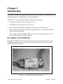
Description of the GPIB-130
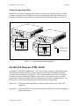
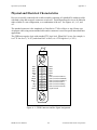
The high-speed GPIB-130 bus extender (shown in Figure 1-1) is used in pairs with a special
parallel data transmission cable to connect two separate GPIB (IEEE 488) bus systems in a
functionally transparent manner.
Figure 1-1. The Model GPIB-130 Bus Extender
© National Instruments Corporation
1-1
GPIB-130 User Manual
Introduction
Chapter 1
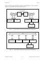
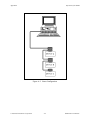
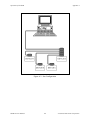
While the two bus systems are physically separate, as shown in Figure 1-2, devices logically
appear to be located on the same bus as shown in Figure 1-3.
RS-422 Compatible
Transmission
Lines
GPIB #1
Computer
(System Controller,
Talker, and Listener)
GPIB-130
GPIB-130
Printer
(Listener)
GPIB #2
Multimeter
(Talker and Listener)
Signal Generator
(Listener)
Unit Under Test
Figure 1-2. Typical GPIB-130 Extension System (Physical Configuration)
GPIB
Computer
(System Controller,
Talker, and Listener)
Printer
(Listener)
Multimeter
(Talker and Listener)
Signal Generator
(Listener)
Unit Under Test
Figure 1-3. Typical GPIB-130 Extension System (Logical Configuration)
GPIB-130 User Manual
1-2
© National Instruments Corporation
Chapter 1
Introduction
With the GPIB-130, it is possible to overcome the following two configuration restrictions
imposed by ANSI/IEEE Standard 488.1-1987:
•
A cable length limit of 20 m total per contiguous bus or 2 m times the number of devices on
the bus, whichever is smaller
•
An electrical loading limit of 15 devices per contiguous bus
Each GPIB-130 system extends the distance limit by 300 m and the loading limit to 30 devices
(including the extenders), without sacrificing speed or performance. These point-to-point
extender systems can be connected in series for longer distances or in star patterns for additional
loading.
The maximum data transfer rate over the extension is 900 kbytes/sec. Furthermore, there is no
speed degradation at all for transfers between devices on the same side of the extension.
Because the GPIB-130 is a functionally transparent extender, the same GPIB communications
and control programs that work with an unextended system can work unmodified with an
extended system. There is one minor exception to this transparency in conducting parallel polls,
as explained in Chapter 3 in the section Parallel Poll Response (PPR) Modes.
What Your Kit Should Contain
Your GPIB-130 kit should contain the following components:
Kit Component
Part Number
GPIB-130 Bus Extender
181460-01
One of the following power supplies:
• 100-120 VAC (5V-regulated, 700mA)
or
• 220-240 VAC (5V-regulated, 1A)
GPIB-130 User Manual
© National Instruments Corporation
181626-01
181626-31
320391-01
1-3
GPIB-130 User Manual
Introduction
Chapter 1
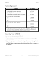
Optional Equipment
Equipment
Part Number
Transmission Cables:
•
Type T5 (NEC CL2 rated) – up to 50 m
•
Type T2 (NEC CL2 rated) – 0 m to 300 m
•
Type T6 (NEC CL2P-Plenum rated) – 0 m to 300 m
(xxx = length in meters)
181563-xxx
178056-xxx
181564-xxx
Type X1 GPIB Cable (Single-Shielded)*:
•
1m
763001-01
•
2m
•
4m
763001-02
763001-03
Type X2 GPIB Cable (Double-Shielded)*:
763061-01
763061-02
763061-03
•
1m
•
2m
•
4m
*
To meet FCC emission limits for this Class A device, you must use a shielded (Type X1
or X2) GPIB cable. Operating this equipment with a non-shielded cable may cause
interference to radio and television reception in commercial areas.
Unpacking Your GPIB-130
Follow these steps when unpacking your GPIB-130.
1. Verify that the pieces contained in the package you received match the kit parts list given
earlier in this section.
2. Inspect the shipping container and contents for damage. If the container is damaged and the
damage appears to have been caused in shipment, file a claim with the carrier. If the
equipment is damaged, do not attempt to operate it. Contact National Instruments for
instructions. Retain the shipping material for possible inspection by carrier or reshipment of
the equipment.
GPIB-130 User Manual
1-4
© National Instruments Corporation
Chapter 2
Connection
This chapter contains information for connecting your GPIB-130.
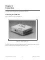
Connecting the GPIB-130
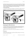
Figure 2-1 shows a side view of the GPIB-130.
Figure 2-1. GPIB-130 Side View
The GPIB-130 may be powered on from either an external 5V regulated power supply or from a
specially configured National Instruments GPIB interface board.
© National Instruments Corporation
2-1
GPIB-130 User Manual
Connection
Chapter 2
Connecting an External Power Supply
Caution: Not for installation in air ducts or plenums. For installation in other environmental
air handling spaces, use only with cable classified by U.L. Inc. as to fire and smoke
characteristics in accordance with section 725.2(B) of the National Electrical Code.
To connect an external power supply to the GPIB-130, complete the following steps.
Caution: Failure to follow these steps for installation may result in damage to your GPIB-130
and your system.
1.
Make sure that the power switch on the side panel is in the off position.
2.
Inspect the power supply to confirm that it is compatible with the line voltage available
from the wall outlet.
3.
Push the phono-jack connector of the external power supply into the 5VDC jack of the
GPIB-130.
4.
Turn the phono-jack connector so that it screws into the threading on the 5VDC jack.
5.
Plug the power supply into the wall outlet.
6.
Connect the transmission cable to both GPIB-130s.
7.
Slide the power switch of both extenders to the on position.
The GPIB-130 extension is now operational.
Connecting to a Specially Configured GPIB Interface Board
To connect the GPIB-130 to a specially equipped National Instruments GPIB interface board,
complete the following steps.
Caution: Failure to follow these steps for installation may result in damage to your GPIB-130
and your system.
1.
Make sure that the power switch on the side panel is in the off position.
2.
Turn off the computer containing the interface board.
3.
Unplug the power cord of the computer.
4.
Push either phono-jack connector of the special power cord into the 5VDC jack of the
GPIB-130.
5.
Turn the phono-jack connector so that it screws into the threading on the 5VDC jack on
the GPIB-130.
GPIB-130 User Manual
2-2
© National Instruments Corporation
Chapter 2
Connection
6.
Push the other phono-jack connector of the special power cord into the 5VDC jack of the
National Instruments interface board.
7.
Turn the phono-jack connector so that it screws into the threading on the 5VDC jack on
the interface board.
8.
Plug in the power cord of the computer and turn on the computer.
9.
Connect the transmission cable to both GPIB-130s.
10.
Slide the power switch of both extenders to the on position.
The GPIB-130 extension is now operational.
Connecting to Hewlett-Packard Controllers
To achieve very high data transfer rates and long cable spans between devices, many HP
Controllers and computers, such as the 64000 series, use a preload technique on the unit
designated Master Controller. When preloaded, the GPIB lines of the Master Controller are
terminated to represent six device loads. HP has two types of preloading: Class A, in which all
16 GPIB lines are loaded, and Class B, in which all lines, except NRFD and NDAC lines, are
loaded.
Preloading increases ringing on signal transitions and can cause improper operation of the
GPIB-130s. If this happens, set all signals on the Master Controller to normal (1 unit) load. This
is done using a back panel switch on your HP Controller. In addition, you must also strictly
conform to the cabling rule of no more than two meters per device.
© National Instruments Corporation
2-3
GPIB-130 User Manual
Chapter 3
Configuration and Operation
This chapter describes how to configure and operate a GPIB-130 system.
Operating Modes
The GPIB-130 has two operating modes: Unbuffered mode and Buffered mode. The operating
mode determines how data is transmitted across the extension. Both units in the extension
system must be set to the same mode.
Unbuffered Mode
In Unbuffered mode, each data byte is transmitted using the GPIB double interlocked
handshaking protocol. For long data streams, transfers using Unbuffered mode are slower than
transfers using Buffered mode. However, the GPIB extension is transparent in Unbuffered
mode.
Buffered Mode
In Buffered mode, the GPIB-130 uses FIFOs to buffer data between the remote and local units.
For long data streams, you can obtain a much higher data throughput with Buffered mode than
with Unbuffered mode.
Consider the following situation: a GPIB device on the local side of the extension is addressed to
talk; another device on the remote side is addressed to listen. When the talking device sources
data bytes, the GPIB-130s accept the data bytes and store them in a FIFO. At the same time, the
GPIB-130s read data from the FIFO and source data bytes to the Listener. Whenever the FIFO
contains data, the number of bytes sourced by the Talker differs from the number of bytes
accepted by the Listener. A few applications may not operate properly in Buffered mode.
GPIB command bytes are not stored in the FIFOs; they are transmitted using the GPIB double
interlocked handshaking protocol.
In most applications, the GPIB-130s should be configured in Buffered mode.
© National Instruments Corporation
3-1
GPIB-130 User Manual
Configuration and Operation
Chapter 3
Setting the Operating Mode
Both GPIB-130s in the extension system must be set to the same operating mode. Use switch
position 1 on the side of each GPIB-130 to set the operating mode. Slide the switch to the up
position to set Buffered mode; slide the switch down to set Unbuffered mode. See Figure 3-1.
...
....
On O
ff
....
.
...
....
On O
ff
Buffered
Unbuffered
PPoll Im
PPoll St
....
.
Key
= Buffer position
A. Buffered Mode
Buffered
Unbuffered
= PPoll position
PPoll Im
PPoll St
B. Unbuffered Mode
Figure 3-1. Switch Setting for Operating Mode
Parallel Poll Response (PPR) Modes
According to ANSI/IEEE Standard 488.1-1987, devices must respond to a parallel poll within
200 nsec after the Identify (IDY) message (Attention (ATN) and End Or Identify (EOI)) is
asserted by the Controller-In-Charge (CIC). The Controller then waits at least 2 µsec before
reading the Parallel Poll Response (PPR). In many cases, a remote device on an extended
system cannot respond to Parallel Polls this quickly because of cable propagation delays. The
GPIB-130s can solve this problem using one of the following two approaches:
Approach 1:
Respond to IDY within 200 nsec with the results of the previous poll of the
remote bus.
Approach 2:
Ignore the 200 nsec rule and assume that the Controller will wait long enough to
capture the response.
GPIB-130 User Manual
3-2
© National Instruments Corporation
Chapter 3
Configuration and Operation
Stored PPR Mode (Approach 1)
In the stored PPR mode, the GPIB-130s use an internal PPR data register. When a Controller on
the local GPIB system asserts IDY, the local GPIB-130 extender responds by outputting the
contents of the PPR data register to the local GPIB data lines. At the same time, a parallel poll
message is sent to the remote bus. When the local IDY signal is unasserted, the PPR from the
remote system is loaded into the internal PPR data register. Consequently, the register always
contains the response of the previous complete poll. To obtain the response of both local and
remote GPIB systems, the control program executes two parallel polls back-to-back and uses the
second response.
The software driver library of most Controllers contains an easy-to-use parallel poll function. If,
for example, the function is called ibrpp and the control program is written in BASIC, the
sequence to conduct a poll in Stored PPR mode might be similar to the following sequence:
.
.
.
CALL ibrpp (brd0%, ppr%)
CALL ibrpp (brd0%, ppr%)
IF ppr > 0 GOTO 300
.
.
.
Immediate PPR Mode (Approach 2)
In this mode, the GPIB-130s do not use the internal PPR data register. When a Controller on the
local GPIB system asserts IDY, the local GPIB-130 extender sends the IDY message to the
remote bus and the response is returned as fast as propagation delays permit. The Controller
must allow time to receive the response.
Choosing the PPR Mode
Choosing the right PPR depends on the type of Controllers present in the GPIB system and the
length of cable between the GPIB-130s. Of course, if the control program does not use parallel
polls, the PPR mode does not matter.
Many Hewlett-Packard GPIB Controllers remain in a parallel poll state with IDY asserted
whenever they are not performing another function. A change in the response causes an interrupt
of the control program. In other Controllers, the IDY signal is toggled on and off and the
duration of the signal can be varied to accommodate delayed responses over extenders. When
used with these types of Controllers, the GPIB-130 should be set to Immediate PPR mode.
Most other Controllers pulse the IDY signal for about 2 µsec and expect a response within that
time. When used with this type of Controller, the GPIB-130 should use the Stored PPR mode if
the cable between the extenders is longer than about 60 m. For shorter cable distances, using the
Immediate PPR mode is recommended.
© National Instruments Corporation
3-3
GPIB-130 User Manual
Configuration and Operation
Chapter 3
Both GPIB-130s in the extension system do not need to be set to the same PPR mode. The PPR
mode of the local GPIB-130 should be chosen to accommodate the Controllers on the local GPIB
system. Likewise, the PPR mode of the remote GPIB-130 should be chosen to accommodate the
Controllers on the remote GPIB system. If no Controllers are physically connected to one of the
GPIB-130s, the PPR mode of that GPIB-130 has no effect on the system.
Setting the PPR Mode
Use switch position 2 on the side of each GPIB-130 to set the PPR mode. Slide the switch to the
up position to set Immediate PPR mode; slide the switch down to set Stored PPR mode. See
Figure 3-2.
...
....
On O
ff
....
.
..
....
On O
ff
uffered
uffered
PPoll Imm.
PPoll Stored
A. Immediate PPR Mode
(Default)
....
..
Key
= PPoll position
uffered
uffered
PPoll Imm.
PPoll Stored
= Buffer position
B. Stored PPR Mode
Figure 3-2. Switch Setting for Parallel Poll Response (PPR) Mode
Operating the GPIB-130 System
The GPIB-130 extension system is fully operational when power is applied to both units. In
some systems, it is necessary to power on the System Controller device last, after the extenders
and all other devices are operating. This power-on sequence is necessary if the System
Controller executes only one IFC shortly after power-on.
The GPIB-130 has four indicator LEDs on the top of the box labeled Power, Link, Talk, and
Listen.
Power LED
The Power LED is lit whenever power is applied to the GPIB-130 and the power switch on the
side of the box is in the on position.
GPIB-130 User Manual
3-4
© National Instruments Corporation
Chapter 3
Configuration and Operation
Link LED
The Link LED is lit whenever both GPIB-130s are powered on and the transmission cable is
properly connected to both extenders. During operation, the Link LED turns off if the cable is
disconnected from either end of the extension, or if either GPIB-130 is powered off.
Talk LED
The Talk LED is lit whenever a device on the local GPIB system is identified as a Talker, or if a
Controller on the local GPIB system is actively asserting the ATN message. Whenever the Talk
LED of the local GPIB-130 is lit, the Listen LED of the remote GPIB-130 is lit.
Listen LED
The Listen LED is lit whenever a device on the remote GPIB system is identified as a Talker, or
if a Controller on the remote GPIB system is actively asserting the ATN message. Whenever the
Listen LED of the local GPIB-130 is lit, the Talk LED of the remote GPIB-130 is lit.
© National Instruments Corporation
3-5
GPIB-130 User Manual
Chapter 4
Theory of Operation
This chapter describes how the GPIB-130 circuitry operates. This chapter assumes that you have
a basic knowledge of the GPIB. If you are a first-time user or you would like to review the
basics, refer to Appendix A, Operation of the GPIB, for a history and the basic operation of the
GPIB.
Figure 4-1 shows a block diagram of the GPIB-130.
System
Controller
Detection
GPIB
Tranceivers
Parallel
Poll
Detection
PPR
Register
FIFO
Controller
FIFO
Source
Handshake
Detection
RS-422 Transceivers
GPIB
CIC
Detection
Figure 4-1. GPIB-130 Block Diagram
Power-On (PON) State
The GPIB-130s enter the Power-On (PON) state when you first turn them on. The GPIB-130s
remain in the PON state until the transmission cable is properly connected to both GPIB-130s.
In the PON state, all state machines and FIFOs are cleared. No GPIB lines are asserted by the
GPIB-130 in the PON state.
© National Instruments Corporation
4-1
GPIB-130 User Manual
Theory of Operation
Chapter 4
When the GPIB-130s leave the PON state, the Link LED turns on and the extension system
becomes operational.
System Controller Detection
The System Controller Detection circuitry locates the GPIB System Controller if one is present
in the system. The System Controller may be on either the local side or the remote side of the
GPIB-130 extension.
The ANSI/IEEE Standard 488.1-1987 restricts a GPIB system to having only one System
Controller. However, the GPIB-130s work in systems that have more than one System
Controller. A GPIB device should assert the Interface Clear (IFC) message to become the
System Controller.
Controller-In-Charge Detection
The Controller-In-Charge (CIC) Detection circuitry locates the GPIB Controller-In-Charge if one
is present in the system. The GPIB Controllers may be on the local side, the remote side, or both
sides of the GPIB-130 extension. Devices on one side of the extension system may pass control
or take control from devices on the remote side of the extension.
Source Handshake Detection
The Source Handshake Detection circuitry locates the device sourcing GPIB command or data
bytes. Command bytes may be sourced by the CIC; data bytes may be sourced by the addressed
GPIB Talker.
One or more devices in the system may be addressed as GPIB Listeners. Listeners may be on
the same side, the opposite side, or both sides of the GPIB-130 extension.
Parallel Poll Detection
The Parallel Poll Detection circuitry determines when the CIC is conducting a parallel poll. The
GPIB-130 responds to parallel polls according to the Parallel Poll Response (PPR) mode chosen
by the position of switch 2 (see the Parallel Poll Response (PPR) Modes section in Chapter 3).
Devices on both sides of the extension may respond to parallel polls.
FIFO Controller
The FIFO Controller manages data flow into and out of the GPIB-130's FIFO. For long data
streams, you can obtain a much higher data throughput with Buffered mode than with
Unbuffered mode. The FIFO Controller remains inactive unless a device is sourcing data bytes
and the GPIB-130 is configured to be in Buffered mode. See the Operating Modes section in
Chapter 3.
Each GPIB-130 contains a FIFO and the FIFO Controller circuitry, so GPIB Talkers on both
sides of the extension can use Buffered mode.
GPIB-130 User Manual
4-2
© National Instruments Corporation
Appendix A
Operation of the GPIB
Communication among interconnected GPIB devices is achieved by passing messages through
the interface system.
Types of Messages
The GPIB carries device-dependent messages and interface messages.
•
Device-dependent messages, often called data or data messages, contain device-specific
information such as programming instructions, measurement results, machine status, and data
files.
•
Interface messages manage the bus itself. They are usually called commands or command
messages. Interface messages perform such tasks as initializing the bus, addressing and
unaddressing devices, and setting device modes for remote or local programming.
The term command as used here should not be confused with some device instructions which can
also be called commands. Such device-specific instructions are actually data messages.
Talkers, Listeners, and Controllers
A Talker sends data messages to one or more Listeners. The Controller manages the flow of
information on the GPIB by sending commands to all devices.
Devices can be Listeners, Talkers, and/or Controllers. A digital voltmeter, for example, is a
Talker and may be a Listener as well.
The GPIB is a bus like an ordinary computer bus, except that the computer has its circuit cards
interconnected via a backplane bus, whereas the GPIB has standalone devices interconnected via
a cable bus.
The role of the GPIB Controller can also be compared to the role of the CPU of a computer, but
a better analogy is to the switching center of a city telephone system. The switching center
(Controller) monitors the communications network (GPIB). When the center (Controller)
notices that a party (device) wants to make a call (send a data message), it connects the caller
(Talker) to the receiver (Listener).
The Controller addresses a Talker and a Listener before the Talker can send its message to the
Listener. After the message is transmitted, the Controller may unaddress both devices.
Some bus configurations do not require a Controller. For example, one device may always be a
Talker (called a Talk-only device) and there may be one or more Listen-only devices.
© National Instruments Corporation
A-1
GPIB-130 User Manual
Operation of the GPIB
Appendix A
A Controller is necessary when the active or addressed Talker or Listener must be changed. The
Controller function is usually handled by a computer.
With the GPIB interface board and its software your personal computer plays all three roles.
•
Controller - to manage the GPIB
•
Talker - to send data
•
Listener - to receive data
The Controller-In-Charge and System Controller
Although there can be multiple Controllers on the GPIB, only one Controller at a time is active
or Controller-In-Charge (CIC). Active control can be passed from the current CIC to an idle
Controller. Only one device on the bus, the System Controller, can make itself the CIC. The
GPIB interface board is usually the System Controller.
GPIB Signals and Lines
The interface system consists of 16 signal lines and 8 ground return or shield drain lines.
The 16 signal lines are divided into the following three groups.
•
Eight data lines
•
Three handshake lines
•
Five interface management lines
Data Lines
The eight data lines, DIO1 through DIO8, carry both data and command messages. All
commands and most data use the 7-bit ASCII or ISO code set, in which case the eighth bit,
DIO8, is unused or used for parity.
Handshake Lines
Three lines asynchronously control the transfer of message bytes among devices. The process is
called a three-wire interlocked handshake, and it guarantees that message bytes on the data lines
are sent and received without transmission error.
Not Ready For Data (NRFD)
NRFD indicates when a device is ready or not ready to receive a message byte. The line is
driven by all devices when receiving commands and by Listeners when receiving data messages.
GPIB-130 User Manual
A-2
© National Instruments Corporation
Appendix A
Operation of the GPIB
Not Data Accepted (NDAC)
NDAC indicates when a device has or has not accepted a message byte. The line is driven by all
devices when receiving commands and by Listeners when receiving data messages.
Data Valid (DAV)
DAV tells when the signals on the data lines are stable (valid) and can be accepted safely by
devices. The Controller drives DAV when sending commands and the Talker drives it when
sending data messages.
Interface Management Lines
Five lines are used to manage the flow of information across the interface.
Attention (ATN)
The Controller drives ATN true when it uses the data lines to send commands and false when it
allows a Talker to send data messages.
Interface Clear (IFC)
The System Controller drives the IFC line to initialize the bus and become CIC.
Remote Enable (REN)
The System Controller drives the REN line, which is used to place devices in remote or local
program mode.
Service Request (SRQ)
Any device can drive the SRQ line to asynchronously request service from the Controller with
the SRQ line.
End Or Identify (EOI)
The EOI line has two purposes. The Talker uses the EOI line to mark the end of a message
string. The Controller uses the EOI line to tell devices to identify their response in a parallel
poll.
© National Instruments Corporation
A-3
GPIB-130 User Manual
Operation of the GPIB
Appendix A
Physical and Electrical Characteristics
Devices are usually connected with a cable assembly consisting of a shielded 24 conductor cable
with both a plug and receptacle connector at each end. This design allows devices to be linked in
either a linear or a star configuration, or a combination of the two. See Figures A-1, A-2, and
A-3.
The standard connector is the Amphenol or Cinch Series 57 Microribbon or Amp Champ type.
An adapter cable using a non-standard cable and/or connector is used for special interconnection
applications.
The GPIB uses negative logic with standard TTL logic level. When DAV is true, for example, it
is a TTL low level ( ≤ 0.8V), and when DAV is false, it is a TTL high level ( ≥ 2.0V).
DIO1
DIO2
DIO3
DIO4
EOI
DAV
NRFD
NDAC
IFC
SRQ
ATN
Shield
1
2
3
4
5
6
7
8
9
10
11
12
13
14
15
16
17
18
19
20
21
22
23
24
DIO5
DIO6
DIO7
DIO8
REN
GND (twisted with DAV)
GND (twisted with NRFD)
GND (twisted with NDAC)
GND (twisted with IFC)
GND (twisted with SRQ)
GND (twisted with ATN)
Signal Ground
Figure A-1. GPIB Connector and the Signal Assignment
GPIB-130 User Manual
A-4
© National Instruments Corporation
Appendix A
Operation of the GPIB
Figure A-2. Linear Configuration
© National Instruments Corporation
A-5
GPIB-130 User Manual
Operation of the GPIB
Appendix A
Figure A-3. Star Configuration
GPIB-130 User Manual
A-6
© National Instruments Corporation
Appendix A
Operation of the GPIB
Configuration Requirements
To achieve the high data transfer rate that the GPIB was designed for, the physical distance
between devices and the number of devices on the bus are limited.
The following restrictions are typical.
•
A maximum separation of four meters between any two devices and an average separation of
two meters over the entire bus.
•
A maximum total cable length of 20 m.
•
No more than 15 devices connected to each bus, with at least two-thirds powered on.
Bus extenders are available from National Instruments for use when these limits must be
exceeded.
Related Document
For more information on topics covered in this section, consult ANSI/IEEE Standard
488.1-1987, IEEE Standard Digital Interface for Programmable Instrumentation.
© National Instruments Corporation
A-7
GPIB-130 User Manual
Appendix B
Specifications
This appendix lists the specifications of the GPIB-130.
System Configuration
Distance per extension
up to 300 m
Loading per extension
up to 14 additional devices
Multiple extensions
permitted in any combination of star or linear pattern
GPIB driver output circuit and T1
timing of source device
no restrictions
Note: T1 is the settling time (DIO valid to DAV) and varies according to the type of drivers and
the system configuration used.
Performance Characteristics
Speed (buffered mode)*
900 kbytes/sec maximum
Speed (unbuffered mode)*
5m
20 m
50 m
100 m
300 m
790 kbytes/sec maximum
640 kbytes/sec maximum
460 kbytes/sec maximum
315 kbytes/sec maximum
140 kbytes/sec maximum
Functionality
transparent GPIB operation except for stored parallel
polls
Interlocked IEEE 488 handshake
maintained across the extension in Unbuffered mode
© National Instruments Corporation
B-1
GPIB-130 User Manual
Specifications
IEEE 488 capability identification
codes
Appendix B
SH1
AH1
T5, TE5
L3, LE3
SR1
RL1
PP1,2
DC1
DT1
C1-5
E2
complete Source Handshake
complete Acceptor handshake
complete Talker
complete Listener
complete Service Request
complete Remote Local
complete Parallel Poll
complete Device Clear
complete Device Trigger
complete Controller
tri-state GPIB drivers
* Maximum sustained transfer rates assuming 1 Mbytes/sec transfer rate without extenders.
GPIB-130 User Manual
B-2
© National Instruments Corporation
Appendix B
Specifications
Operating Characteristics
Architecture
point-to-point (not multi-drop) transmission
Operating modes
Buffered mode or Unbuffered (interlocked) mode
Parallel Poll Response modes
Immediate Parallel Poll Response mode or Stored
Parallel Poll Response mode
Electrical Characteristics
GPIB interface circuit
tri-state drivers (SN75ALS160, SN75ALS162)
Transmission interface circuit
RS-422 drivers and receivers connected with parallel
data transmission cable
GPIB interface load
one standard load, AC and DC
Power
2.2 W typical
Environmental Characteristics
Operating temperature
0o to 55o C
Humidity
5% to 95% non-condensing conditions
FCC
Class A verified
Physical Characteristics
Case dimensions
3.75 x 3.0 x 0.95 in. (95 x 76 x 24 mm)
Case material
0.050 in THK 5052-H32 Aluminum
Rack mounting
Contact factory for information
GPIB cable
IEEE 488 standard 24-pin
Transmission cables
NEC CL2 and CL2P (Plenum) rated cables available
with AMP Amplimite connectors AMP HDP-20 50
pin connector with RFI/EMI shield
© National Instruments Corporation
B-3
GPIB-130 User Manual
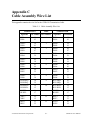
Appendix C
Cable Assembly Wire List
This appendix contains the wire list for the GPIB-130 Transmission Cable.
Table C-1. Cable Assembly Wire List
Connector P2A
Signature
Cable
Pin Number Pair Number
Connector P2B
Signature
Pin Number
DIO1+
DIO1-
44
43
1
DIO1+
DIO1-
44
43
DIO2+
DIO2-
34
41
2
DIO2+
DIO2-
34
41
DIO3+
DIO3-
48
47
3
DIO3+
DIO3-
48
47
DIO4+
DIO4-
36
39
4
DIO4+
DIO4-
36
39
DIO5+
DIO5-
42
18
5
DIO5+
DIO5-
42
18
DIO6+
DIO6-
45
46
6
DIO6+
DIO6-
45
46
DIO7+
DIO7-
40
35
7
DIO7+
DIO7-
40
35
DIO8+
DIO8-
37
38
8
DIO8+
DIO8-
37
38
BUS SRQ+
BUS SRQ-
30
32
9
BUS SRQ+
BUS SRQ-
30
32
BUS REN+
BUS REN-
14
15
10
BUS REN+
BUS REN-
14
15
BUSPP+
BUSPP-
16
17
11
BUSPP+
BUSPP-
16
17
XIFC+
XIFC-
29
12
12
RIFC+
RIFC-
31
33
RIFC+
RIFC-
31
33
13
XIFC+
XIFC-
29
12
(continues)
© National Instruments Corporation
C-1
GPIB-130 User Manual
Cable Assembly Wire List
Appendix C
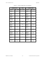
Table C-1. Cable Assembly Wire List (continued)
Connector P2A
Signature
Cable
Pin Number Pair Number
Connector P2B
Signature
Pin Number
XATN+
XATN-
27
11
14
RATN+
RATN-
8
1
XRFD+
XRFD-
21
22
15
RRFD+
RRFD-
3
6
RRFD+
RRFD-
3
6
16
XRFD+
XRFD-
21
22
BUSDAC+
BUSDAC-
5
28
17
BUSDAC+
BUSDAC-
5
28
XEOI+
XEOI-
25
9
18
REOI+
REOI-
2
7
REOI+
REOI-
2
7
19
XEOI+
XEOI-
25
9
XDAV+
XDAV-
10
26
20
RDAV+
RDAV-
4
13
RDAV+
RDAV-
4
13
21
XDAV+
XDAV-
10
26
XPON+
XPON-
24
23
22
RPON+
RPON-
20
19
RATN+
RATN-
8
1
23
XATN+
XATN-
27
11
RPON+
RPON-
20
19
24
XPON+
XPON-
24
23
SHIELD
49
50
SHIELD
49
50
GPIB-130 User Manual
C-2
© National Instruments Corporation
Appendix D
Multiline Interface Messages
This section contains an interface message reference list, which describes the mnemonics and
messages that correspond to the interface functions. These multiline interface messages are sent
and received with ATN TRUE.
For more information on these messages, refer to the ANSI/IEEE Standard 488.1-1987,
IEEE Standard Digital Interface for Programmable Instrumentation.
© National Instruments Corporation
D-1
GPIB-130 User Manual
Multiline Interface Messages
Appendix D
Multiline Interface Messages
Hex
Oct
Dec
ASCII
00
01
02
03
04
05
06
07
000
001
002
003
004
005
006
007
0
1
2
3
4
5
6
7
08
09
0A
0B
0C
0D
0E
0F
010
011
012
013
014
015
016
017
8
9
10
11
12
13
14
15
BS
HT
LF
VT
FF
CR
SO
SI
10
11
12
13
14
15
16
17
020
021
022
023
024
025
026
027
16
17
18
19
20
21
22
23
DLE
DC1
DC2
DC3
DC4
NAK
SYN
ETB
18
19
1A
1B
1C
1D
1E
1F
030
031
032
033
034
035
036
037
24
25
26
27
28
29
30
31
CAN
EM
SUB
ESC
FS
GS
RS
US
NUL
SOH
STX
ETX
EOT
ENQ
ACK
BEL
Msg
GTL
SDC
PPC
GET
TCT
LLO
DCL
PPU
SPE
SPD
Hex
Oct
Dec
ASCII Msg
20
21
22
23
24
25
26
27
040
041
042
043
044
045
046
047
32
33
34
35
36
37
38
39
SP
!
"
#
$
%
&
'
MLA0
MLA1
MLA2
MLA3
MLA4
MLA5
MLA6
MLA7
28
29
2A
2B
2C
2D
2E
2F
050
051
052
053
054
055
056
057
40
41
42
43
44
45
46
47
(
)
*
+
,
.
/
MLA8
MLA9
MLA10
MLA11
MLA12
MLA13
MLA14
MLA15
30
31
32
33
34
35
36
37
060
061
062
063
064
065
066
067
48
49
50
51
52
53
54
55
0
1
2
3
4
5
6
7
MLA16
MLA17
MLA18
MLA19
MLA20
MLA21
MLA22
MLA23
38
39
3A
3B
3C
3D
3E
3F
070
071
072
073
074
075
076
077
56
57
58
59
60
61
62
63
8
9
:
;
<
=
>
?
MLA24
MLA25
MLA26
MLA27
MLA28
MLA29
MLA30
UNL
Message Definitions
DCL
GET
GTL
LLO
MLA
MSA
MTA
PPC
PPD
Device Clear
Group Execute Trigger
Go To Local
Local Lockout
My Listen Address
GPIB-130 User Manual
D-2
My Secondary Address
My Talk Address
Parallel Poll Configure
Parallel Poll Disable
© National Instruments Corporation
Appendix D
Multiline Interface Messages
Multiline Interface Messages
Hex
Oct
40
41
42
43
44
45
46
47
100
101
102
103
104
105
106
107
64
65
66
67
68
69
70
71
@
A
B
C
D
E
F
G
48
49
4A
4B
4C
4D
4E
4F
110
111
112
113
114
115
116
117
72
73
74
75
76
77
78
79
50
51
52
53
54
55
56
57
120
121
122
123
124
125
126
127
58
59
5A
5B
5C
5D
5E
5F
130
131
132
133
134
135
136
137
PPE
PPU
SDC
SPD
Dec ASCII
Msg
Hex
Oct
Dec
MTA0
MTA1
MTA2
MTA3
MTA4
MTA5
MTA6
MTA7
60
61
62
63
64
65
66
67
140
141
142
143
144
145
146
147
96
97
98
99
100
101
102
103
`
a
b
c
d
e
f
g
MSA0,PPE
MSA1,PPE
MSA2,PPE
MSA3,PPE
MSA4,PPE
MSA5,PPE
MSA6,PPE
MSA7,PPE
H
I
J
K
L
M
N
O
MTA8
MTA9
MTA10
MTA11
MTA12
MTA13
MTA14
MTA15
68
69
6A
6B
6C
6D
6E
6F
150
151
152
153
154
155
156
157
104
105
106
107
108
109
110
111
h
i
j
k
l
m
n
o
MSA8,PPE
MSA9,PPE
MSA10,PPE
MSA11,PPE
MSA12,PPE
MSA13,PPE
MSA14,PPE
MSA15,PPE
80
81
82
83
84
85
86
87
P
Q
R
S
T
U
V
W
MTA16
MTA17
MTA18
MTA19
MTA20
MTA21
MTA22
MTA23
70
71
72
73
74
75
76
77
160
161
162
163
164
165
166
167
112
113
114
115
116
117
118
119
p
q
r
s
t
u
v
w
MSA16,PPD
MSA17,PPD
MSA18,PPD
MSA19,PPD
MSA20,PPD
MSA21,PPD
MSA22,PPD
MSA23,PPD
88
89
90
91
92
93
94
95
X
Y
Z
[
\
]
^
_
MTA24
MTA25
MTA26
MTA27
MTA28
MTA29
MTA30
UNT
78
79
7A
7B
7C
7D
7E
7F
170
171
172
173
174
175
176
177
120
121
122
123
124
125
126
127
x
y
z
{
|
}
~
DEL
MSA24,PPD
MSA25,PPD
MSA26,PPD
MSA27,PPD
MSA28,PPD
MSA29,PPD
MSA30,PPD
SPE
TCT
UNL
UNT
Parallel Poll Enable
Parallel Poll Unconfigure
Selected Device Clear
Serial Poll Disable
© National Instruments Corporation
D-3
ASCII
Msg
Serial Poll Enable
Take Control
Unlisten
Untalk
GPIB-130 User Manual
Appendix E
Customer Communication
___________________________________________________
For your convenience, this appendix contains forms to help you gather the information necessary
to help us solve technical problems you might have as well as a form you can use to comment on
the product documentation. Filling out a copy of the Technical Support Form before contacting
National Instruments helps us help you better and faster.
National Instruments provides comprehensive technical assistance around the world. In the U.S.
and Canada, applications engineers are available Monday through Friday from 8:00 a.m. to
6:00 p.m. (central time). In other countries, contact the nearest branch office. You may fax
questions to us at any time.
Corporate Headquarters
(512) 795-8248
Technical support fax: (800) 328-2203
(512) 794-5678
Branch Offices
Australia
Austria
Belgium
Denmark
Finland
France
Germany
Italy
Japan
Netherlands
Norway
Spain
Sweden
Switzerland
U.K.
Phone Number
(03) 879 9422
(0662) 435986
02/757.00.20
45 76 26 00
(90) 527 2321
(1) 48 14 24 00
089/741 31 30
02/48301892
(03) 3788-1921
03480-33466
32-848400
(91) 640 0085
08-730 49 70
056/20 51 51
0635 523545
© National Instruments Corporation
Fax Number
(03) 879 9179
(0662) 437010-19
02/757.03.11
45 76 71 11
(90) 502 2930
(1) 48 14 24 14
089/714 60 35
02/48301915
(03) 3788-1923
03480-30673
32-848600
(91) 640 0533
08-730 43 70
056/27 00 25
0635 523154
E-1
GPIB-130 User Manual
Technical Support Form
___________________________________________________
Photocopy this form and update it each time you make changes to your software or hardware, and use the completed
copy of this form as a reference for your current configuration. Completing this form accurately before contacting
National Instruments for technical support helps our applications engineers answer your questions more efficiently.
If you are using any National Instruments hardware or software products related to this problem, include the
configuration forms from their user manuals. Include additional pages if necessary.
Name
Company
Address
Fax (
)
Phone (
Computer brand
)
Model
Processor
Operating system
Speed
Mouse
MHz
RAM
yes
Hard disk capacity
no
M
M
Display adapter
Other adapters installed
Brand
Instruments used
National Instruments hardware product model
Revision
Configuration
National Instruments software product
Configuration
The problem is
List any error messages
The following steps will reproduce the problem
Version
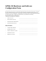
GPIB-130 Hardware and Software
Configuration Form
___________________________________________________
Record the settings and revisions of your hardware and software on the line to the right of each item. Complete a
new copy of this form each time you revise your software or hardware configuration, and use this form as a
reference for your current configuration. Completing this form accurately before contacting National Instruments
for technical support helps our applications engineers answer your questions more efficiently.
National Instruments Products
•
GPIB-130 Revision
_________________________________________________
•
Remote GPIB-130 Revision
_________________________________________________
•
National Instruments GPIB Interface
•
National Instruments Software
________________________________________________
_________________________________________________
Other Products
•
Computer Make and Model
_________________________________________________
•
Operating System Version
_________________________________________________
•
Number of GPIB Devices on Bus
_________________________________________________
•
Other Boards in System
_________________________________________________
•
GPIB Devices in System
_________________________________________________
Documentation Comment Form
___________________________________________________
National Instruments encourages you to comment on the documentation supplied with our products. This
information helps us provide quality products to meet your needs.
Title:
GPIB-130 User Manual
Edition Date:
November 1993
Part Number:
370897A-01
Please comment on the completeness, clarity, and organization of the manual.
If you find errors in the manual, please record the page numbers and describe the errors.
Thank you for your help.
Name
Title
Company
Address
Phone
Mail to:
(
)
Technical Publications
National Instruments Corporation
6504 Bridge Point Parkway, MS 53-02
Austin, TX 78730-5039
Fax to:
Technical Publications
National Instruments Corp.
MS 53-02
(512) 794-5678
Glossary
Prefix
mµn-
%
°
>
≥
<
≤
A
AC
ANSI
ASCII
ATN
C
CIC
CPU
DAV
DC
DIO
EOI
FCC
FIFO
GND
GPIB
IDY
IEEE
IFC
ISO
kbytes
LED
m
M
NDAC
NEC
NRFD
oz.
PON
Meaning
millimicronano-
Value
10-3
10-6
10-9
percent
degrees
greater than
greater than or equal to
less than
less than or equal to
amperes
alternating current
American National Standards Institute
American Standard Code for Information Interchange
Attention
Celsius
Controller-In-Charge
central processing unit
Data Valid
direct current
Data Input/Output
End Or Identify
Federal Communications Commission
first-in-first-out
Ground
General Purpose Interface Bus
Identify
Institute of Electrical and Electronic Engineers
Interface Clear
International Standards Organization
1,000 bytes
light-emitting diode
meters
megabytes of memory
Not Data Accepted
National Electrical Code
Not Ready For Data
ounces
Power On
© National Instruments Corporation
Glossary-1
GPIB-130 User Manual
Glossary
PP
PPR
REN
sec
SRQ
TTL
V
VAC
VDC
W
Parallel Poll
Parallel Poll Response
Remote Enable
seconds
Service Request
transistor-transistor logic
volts
volts alternating current
volts direct currect
watts
GPIB-130 User Manual
Glossary-2
© National Instruments Corporation