1
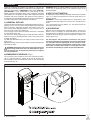
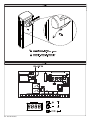
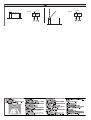
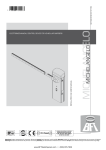
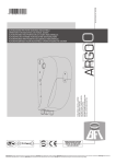
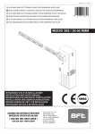
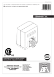
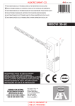
D811528_beta_test 12-01-07
I
AUTOMATISMO ELETTROMECCANICO PER BARRIERA VEICOLARE
GB ELECTROMECHANICAL CONTROL DEVICE FOR VEHICULAR BARRIERS
F AUTOMATISME ELECTROMECANIQUE POUR BARRIERE POUR VÉHICULES
8
027908 3 0 1 4 9 9
D ELEKTROMECHANISCHER ANTRIEB FÜR FAHRZEUGSCHRANKEN
E AUTOMATISMOS ELECTROMECANICOS PARA BARRÉRAS VEHICULAR
P AUTOMATIZAÇÃO ELECTROMECÂNICA PARA BARREIRA VEICULAR
MICHELANGELO
ISTRUZIONI D’USO E DI INSTALLAZIONE
INSTALLATION AND USER’S MANUAL
INSTRUCTIONS D’UTILISATION ET D’INSTALLATION
INSTALLATIONS-UND GEBRAUCHSANLEITUNG
INSTRUCCIONES DE USO Y DE INSTALACION
INSTRUÇÕES DE USO E DE INSTALAÇÃO
Via Lago di Vico, 44
36015 Schio (VI)
Tel.naz. 0445 696511
Tel.int. +39 0445 696533
Fax 0445 696522
Internet: www.bft.it
E-mail: [email protected]
2 - MICHELANGELO
D811528_beta_test
USER’S MANUAL
Thank you for buying this product. Our company is sure that you
will be more than satisfied with the performance of the product. This
product is supplied with a “WARNINGS” leaflet and an “INSTRUCTION MANUAL”. These should both be read carefully as they
provide important information about safety, installation, operation
and maintenance. This product complies with recognised technical
standards and safety regulations. We declare that this product is
in conformity with the following European Directives: 89/336/CEE,
73/23/EEC, 98/37/EEC and subsequent amendments.
1) GENERAL OUTLINE
Compact electromechanical barrier suitable for limiting private areas,
parkings, access areas for vehicles only. Available for passageways
from 6 to 8 metres. Adjustable electronic limit switches, they guarantee correct boom stopping position. In case of intensive use, a
thermal sensor activates the cooling fan.
The emergency release device for manual manoeuvre is controlled
by a personalised key lock.
The actuator is always supplied for left-hand side fitting. However,
when necessary, the opening direction can be reversed by means
of simple operations.
The BM mod. foundation base (on request) makes barrier installation easier.
Appropriate fittings make it easy to install accessories without needing to drill any holes.
WARNING!The barrier must be exclusively used for vehicles to
drive through. Pedestrians must not walk within the operator manoeuvring area. An appropriate pedestrian passageway
must be provided for.
WARNING! When an actuator without bar needs to be released,
ensure that the balancing spring is not compressed (bar in the
opening position).
3) USE OF AUTOMATION
As automation can be remotely controlled and therefore not within
sight, it is essential to frequently check that all safety devices are
perfectly efficient.
WARNING! In case of any malfunction in the safety devices, take
immediate action and require the assistance of a specialised technician.
It is recommended to keep children at a safe distance from the
automation field of action.
4) SCRAPPING
Materials must be disposed of in conformity with the current regulations. In case of scrapping, the automation devices do not entail
any particular risks or danger. In case of recovered materials, these
should be sorted out by type (electrical components, copper, aluminium, plastic etc.).
The descriptions and illustrations contained in the present
manual are not binding.The Company reserves the right to make
any alterations deemed appropriate for the technical, manufacturing and commercial improvement of the product, while
leaving the essential product features unchanged, at any time
and without undertaking to update the present publication.
2) EMERGENCY RELEASE (Fig.1)
The emergency release allows the bar to be manoeuvred manually. It is activated from the outside of the box by inserting the
personalised key into the lock placed under the bar and rotating
it anticlockwise by 90°.
Fig. 1
4 - MICHELANGELO
D811528_beta_test
ENGLISH
D811528_beta_test
INSTALLATION MANUAL
Thank you for buying this product. Our company is sure that you will be
more than satisfied with the performance of the product. This product is
supplied with a “WARNINGS” leaflet and an “INSTRUCTION MANUAL”.
These should both be read carefully as they provide important information about safety, installation, operation and maintenance. This product
complies with recognised technical standards and safety regulations.
We declare that this product is in conformity with the following European Directives: 89/336/CEE, 73/23/EEC, 98/37/EEC and subsequent
amendments.
1) GENERAL OUTLINE
Compact electromechanical barrier suitable for limiting private areas,
parkings, access areas for vehicles only. Available for passageways
from 6 to 8 metres. Adjustable electronic limit switches, they guarantee
correct boom stopping position. In case of intensive use, a thermal sensor activates the cooling fan.
The emergency release device for manual manoeuvre is controlled by
a personalised key lock.
The actuator is always supplied for left-hand side fitting. However,
when necessary, the opening direction can be reversed by means of
simple operations.
The BM mod. foundation base (on request) makes barrier installation
easier.
Appropriate fittings make it easy to install accessories without needing
to drill any holes.
•
•
•
•
•
•
•
•
•
•
•
The LIBRA C MV control panel is supplied by the manufacturer with
standard setting. Any change must be set by means of the incorporated
display or by means of the universal programmer. The Control unit
completely supports the EELINK protocol, including the programmer
self-supply from the control unit.
Its main characteristics are:
- Electronic speed adjustment with slow-down at the end of run.
- Inputs for mechanical position reference elements.
- Separate inputs for safety devices
- Clock input
- Serial protocol connection input
- Incorporated rolling-code radio receiver with transmitter cloning.
The board is provided with a terminal board which can be pulled out for
easier maintenance or replacement. The board is supplied with a series
of pre-wired jumpers to facilitate the installer’s work.
The jumpers relate to the following terminals: 15-17, 15-18, 15-20.. If
the above-mentioned terminals are in use, remove their respective
jumpers.
2) GENERAL SAFETY
WARNING! An incorrect installation or improper use of the product
can cause damage to persons, animals or things.
• The “Warnings” leaflet and “Instruction booklet” supplied with this
product should be read carefully as they provide important information
about safety, installation, use and maintenance.
• Scrap packing materials (plastic, cardboard, polystyrene etc) according to the provisions set out by current standards. Keep nylon
or polystyrene bags out of children’s reach.
• Keep the instructions together with the technical brochure for future
reference.
• This product was exclusively designed and manufactured for the use
specified in the present documentation. Any other use not specified in
this documentation could damage the product and be dangerous.
• The Company declines all responsibility for any consequences resulting
from improper use of the product, or use which is different from that
expected and specified in the present documentation.
• Do not install the product in explosive atmosphere.
• The construction components of this product must comply with the
following European Directives: 89/336/CEE, 73/23/EEC, 98/37/EEC
and subsequent amendments. As for all non-EEC countries, the
above-mentioned standards as well as the current national standards
should be respected in order to achieve a good safety level.
• The Company declines all responsibility for any consequences resulting from failure to observe Good Technical Practice when constructing
closing structures (door, gates etc.), as well as from any deformation
which might occur during use.
• The installation must comply with the provisions set out by the following European Directives: 89/336/CEE, 73/23/EEC, 98/37/EEC
and subsequent amendments.
• Disconnect the electrical power supply before carrying out any work
on the installation. Also disconnect any buffer batteries, if fitted.
• Fit an omnipolar or magnetothermal switch on the mains power sup-
•
•
ENGLISH
ply, having a contact opening distance equal to or greater than 3,5
mm.
Check that a differential switch with a 0.03A threshold is fitted just
before the power supply mains.
Check that earthing is carried out correctly: connect all metal parts
for closure (doors, gates etc.) and all system components provided
with an earth terminal.
Fit all the safety devices (photocells, electric edges etc.) which are
needed to protect the area from any danger caused by squashing,
conveying and shearing, according to and in compliance with the
applicable directives and technical standards.
Position at least one luminous signal indication device (blinker) where
it can be easily seen, and fix a Warning sign to the structure.
The Company declines all responsibility with respect to the automation
safety and correct operation when other manufacturers’ components
are used.
Only use original parts for any maintenance or repair operation.
Do not modify the automation components, unless explicitly authorised
by the company.
Instruct the product user about the control systems provided and the
manual opening operation in case of emergency.
Do not allow persons or children to remain in the automation operation area.
Keep radio control or other control devices out of children’s reach,
in order to avoid unintentional automation activation.
The user must avoid any attempt to carry out work or repair on the
automation system, and always request the assistance of qualified
personnel.
Anything which is not expressly provided for in the present instructions, is not allowed.
Installation must be carried out using the safety devices and controls
prescribed by the EN 12978 Standard.
3) TECHNICAL SPECIFICATIONS
MICHELANGELO
Power supply: .........................................................230V±10% 50Hz(*)
Power absorbed: ......................................................................... 300W
Motor: .................................................................................. 1600 min-1
Absorption: ...................................................................................... 1 A
Cooling intervention temperature: ................................................ 80°C
Internal lubrication: .................................................. permanent grease
Max torque:............................................................................... 600 Nm
Boom length: ............................from 5m to 6m (MICHELANGELO 60)
..................................................from 6m to 8m (MICHELANGELO 80)
Impact reaction: ........................................................................encoder
Manual mechanical release: .........................................customised key
Type of boom:.............................................................................. round
Limit devices: ....... electrical incorporated and electronically adjustable
Maximum no. manoeuvres in 24h (peak):............ continuous operation
Working temperature: ........................................... from -10°C to +55°C
Degree of protection: .................................................................... IP 24
Operator weight (without boom): ............58 Kg (MICHELANGELO 60)
................................................................68 Kg (MICHELANGELO 80)
Dimensions: ............................................................................. see fig.1
(*)= special power supply voltages on request
4) FOUNDATION PLATE (Fig.2)
- Prepare a foundation hole suitable for the particular kind of
ground.
- Layout several raceways for the electric cables to pass through.
- Position the screws supplied with the barrier pack into the 4 fixing
holes with the thread facing upwards. Weld the 4 screw heads to the
base and protect the welds with rust preventer. Position the base so
that it protrudes about 20mm from the floor (fig.2).
- Fill the hole with concrete, checking the position of the base in both
directions by means of a level, and let the cement harden.
5) FITTING OF THE ACTUATOR
WARNING! The barrier must be exclusively used for vehicles to
drive through. Pedestrians must not walk within the operator
manoeuvring area. An appropriate pedestrian passageway must
be provided for.
The passageway must be suitably indicated by means of the warning signs illustrated in Fig.10.
WARNING: before opening the door, the spring must be unloaded
(vertical boom). The door of the box must be facing towards the inside
of the property. When standing in the middle of the passageway, if the
box is on the left the barrier opens to the left, and if the box is on the
right the barrier opens to the right.
MICHELANGELO -
13
INSTALLATION MANUAL
The actuator is always supplied for left-hand side fitting.
5.1) Left-hand fitting
- Fix the operator to the foundation base and secure it by means of nuts M12.
The door of the box must be facing towards the inside of the property.
- The upper surface of the operator is slightly tilted so as to prevent
any rain water from being trapped there. Therefore use a side surface
to check correct positioning by means of a level (fig.2).
- Fit the boom in its opening position (vertical) as indicated in fig.4,
ref.6. The operator balancing is pre-calibrated for the nominal boom
in the opening position (balancing spring stretched).
WARNING! The boom must be positioned so as to have the double
contour facing down (fig.3 ref.10).
- Balance the boom as described in relevant paragraph 6.
5.2) Right-hand fitting
Some internal members need to be moved, with reference to fig. 4 and
the following procedure:
A) Fix the box to the foundation base and lock it in position using M12
nuts (Fig.7 Rif.1).
B) Ensure that the balancing spring is in the opening position (stretched
spring).
C) Completely loosen the spring-stretcher “fig.7/ref.2” in order to remove
the screw “fig.7/ref.3” that secures it to the reduction gear.
WARNING! Never remove the screw in Fig.7 Ref.7 before having
removed the screw in Fig. 7 Ref.3.
D) Remove the boom locking bracket “fig.7/ref.4” and use a CH19
socket spanner to loosen the screw “fig.7/ref.5” until the plate can
be rotated.
E) Turn the lever “fig.7/ref.6” by 90° and insert it correctly in position
C.
F) Tighten the tie rod (fig. 7/ref.5) blocking the lever (fig.7/ref.6) by
means of a torque wrench set at about 80 N/m.
G) Fit the spring unit in the position shown in “fig.7/ref.Dx” by means of
the screw (Ref.7) and the self-locking nut. Then fit screw 3.
H) Adjust the spring stretcher (fig.7/ref.2) until the spring comes under
tension.
I) Refit and partially fix the U bolt (fig.7/ref.4) holding the bar to the
actuator in the opening position.
L) Fit the boom in its opening position (vertical) as indicated in fig.4,
ref.6. The operator balancing is pre-calibrated for the nominal boom
in the opening position (balancing spring stretched).
Fix the boom using the bracket (fig.4 ref.4) and the screws and washers
supplied as standard, then fix the protection cover (fig.4 ref.8) and finally
the screw cover (fig.4 ref.9).
WARNING! The boom must be positioned so as to have the double
contour facing down (fig.4 ref.10).
M) Carry out bar balancing as described in paragraph 7.
N) Set the Direction Reversal logic to ON in the control panel.
Warning: the Direction Reversal logic must be configured to
OFF for left-hand fitted barriers, and to ON for right-hand fitted
barriers. Otherwise, the limit devices will not operate or an encoder
direction error will be displayed.
5.3) Telescopic boom fitting
The internal telescopic boom and the joint are to be fitted in sequence
into the external boom, as from diagram.
5.4) Telescopic boom fixing (Fig.6)
- Once joint B has been fitted to the external boom head, fix it using
the four 3.5 x 25 CH screws (1).
- Insert the internal boom (C) into the external boom by at least 200
mm for MICHELANGELO 60 and by 600 mm for MICHELANGELO
80.
- Then fit the 3.5 x 38 CH screws (2) and the 3.5 x 16 CH screws (3)
with dia.4 washers, by drilling a preparatory hole in the middle of
the passageway using a 3.2 mm bit. Now position the drill bit in the
housing channel found on the outside of the boom.
- The same operation is carried out to fit screws 4 and 5 and respective
washers, at a distance between centres of about 180 mm from the
first ones for MICHELANGELO 60 and 580 mm for MICHELANGELO
80.
- To obtain better system sturdiness, screw 4 is to be fitted diagonally opposite screw 2, and screw 3 is to be fitted diagonally opposite screw 5.
6) BAR BALANCING
- Activate the emergency release (fig.14).
- Position the bar at about 45°. The bar must remain still.
- If the boom tends to open, unload the spring.
14 - MICHELANGELO
-
If the boom tends to close, load the spring.
In both cases, load or unload the spring until the bar remains still at
about 45°.
- Reset the motorised operation by rotating the release key to the
opposi-te direction (fig.14).
WARNING! During the closing operation, the balancing spring must
never be reduced to a pack (be totally compressed).
7) COVER OPENING AND CLOSING
OPENING: having released the cover by turning the key in the lock
(present in the door as seen in Fig.3 ref.1 and 2), lift the cover as far
as the mechanical stop (Fig.8 Ref.B). At this point, push the cover back
until it becomes engaged in the holding pin (Fig.8 Ref.C).
CLOSING: to close the cover, reverse the order of the procedure followed
above. Slightly lift the cover and pull it forward to release it from the holding pin. Then lower the cover while holding it, taking care to insert it in
the groove present in the 2 pieces of the blinker. Finally lock the cover
by turning the key in its vertical position as seen in Fig.3
8) OPTIONAL ACCESSORIES (Fig.13)
Foundation Base - BM
6-m boom light kit - KIT MCL LIGHT
Blinker kit - KIT MCL LAMPO
Moveable boom rest rod - GA
Fixed boom support fork - FAF
Cellula130 post fixing kit - KIT MCL 130
Skirt already assembled to the boom - SB (only for Michelangelo 60)
Safety edge BIR
Lower and/or upper boom covering contour - PCA 3, PCA 6
For further information about the installation and use of accessories,
refer to the respective instruction manuals.
9) Photocell fitting (Fig. 12)
The photocell can be installed on the MICHELANGELO barrier as follows:
1- By directly fixing the CELLULA 130 photocell to the side of the barrier
(Fig. 12 “A”)
2- Fitting the photocell post MCL 130 on the central element (Fig.12 ”B”).
A) Cellula 130 fitting
1) Remove the side with louvres “C” and drill the holes prepared inside,
depending on whether the CELLULA 130 is to be fitted vertically
(Fig.12A) or horizontally.
2) Lay the wiring needed for photocell connection.
3) Fit the photocell as shown in Fig. 12 by means of the appropriate
screws.
Refer to the instruction sheet for Cellula 130 for further information.
B) MCL 130 post fitting
1) Remove the protection (P) cover positioned on the barrier.
2) Lay the wiring needed for photocell connection.
3) Fit post “F” and protection frame “G” as shown in Fig. 12B. The post is
fastened from inside the barrier by means of 3 screws (supplied).
4) Fit the photocell to the post, as shown in the instruction sheet for Cellula 130.
Refer to the instruction sheet for Cellula 130 for further information.
10) ELECTRICAL INSTALLATION SET-UP
WARNING: before opening the door, the spring must be unloaded
(vertical boom). Set up the electrical installation (fig. 10) with reference
to the current regu-lations for electrical installations CEI64-8, IEC364,
in conformity with HD384 and other national standards. Keep the mains
power supply con-nections definitely separate from the service connections (photocells, elec-tric edges, control devices etc.).
Warning! For connection to the mains, use a multipolar cable having
minimum 3x1.5mm2 cross section and complying with the previously
mentioned regulations (for example, if the cable is not protected, it
must be at least equal to H07 RN-F, whereas if it is protected it must
be at least equal to H07 VV-F with a 3x1.5 sq mm2 cross section).
Connect the control and safety devices in conformity with the previously
mentioned installation standards. Fig.10 shows the number of connections and section for a 100m length of power supply cables; for greater
lengths, calculate the section for the true automation load. When the
auxiliary connections exceed 50-metre lengths or go through critical
disturbance areas, it is recommended to decouple the control and safety
devices by means of suitable relays.
The main automation components are (fig.10):
I)
Type-approved adequately rated omnipolar circuit-breaker with
at least 3,5 mm contact opening, provided with protection against
overloads and short circuits, suitable for cutting out automation
from the mains. Place, if not al ready installed, a type-approved
differential switch with a 0.03A threshold just before the automation system.
D811528_beta_test
ENGLISH
D811528_beta_test
INSTALLATION MANUAL
QR) Control panel and incorporated receiver.
S)
Key selector.
AL)
Blinker with tuned antenna.
M)
Actuators.
A)
Bar.
F)
Rest fork.
CS)
Electric edge.
CC)
Edge control.
Ft,Fr) Pair of photocells.
CF)
Photocell post.
T)
1-2-4 channel transmitter.
LOOP)Mass detector loops.
8) LIBRA C MV CONTROL PANEL
Power supply: ......................................................... 230V~±10%
~±10%
±10% 50Hz
Mains/low voltage insulation: ..................................> 2MOhm 500V
Dielectric strength: ................. mains/low voltage 3750V~
~ for 1 minute
Motor output current: ......................... 25A max (MICHELANGELO 60)
........................................................... 30A max (MICHELANGELO 80)
Maximum motor power: ......................... 600 W (MICHELANGELO 60)
............................................................... 750 W (MICHELANGELO 80)
Supply to accessories: ........................24V~
~ (180
180 mA max absorption)
Barrie-open warning light: ..............................................24V~
~ 3W max
Blinker: .........................................................................24V~
~ 25W max
Fuses:...............................................................................see figure 18
12) TERMINAL BOARD CONNECTIONS (Fig.19)
WARNING – During the wiring and installation operations, refer to the
current standards as well as principles of good technical practice.
The cables must be tied by additional fastening next to the terminals,
by means of clips for example.
All the operator wiring operations must be carried out by qualified personnel.
JP4
1-2:
Control for cooling fan
JP10
3-4:
5-6-7-8:
9-10:
11-12:
13-14:
JP11
15-16:
15-17:
15-18:
15-19:
15-20:
JP12
21-22:
Not used
Motor and limit switch connections:
5-15 :closing limit switch
6-7 :motor
8-15 :opening limit switch
Blinker connection (24 V~, 25W)
24 V~ 180mA max output – power supply for photocells
or other devices.
24 V~ 180mA max output – power supply for photocell
transmitters with check (see Fig.19).
START button (N.O.).
STOP button (N.C.). If not used, leave the jumper bridged.
Photocell input (N.C.). If not used, leave the jumper bridged.
Photocell FAULT input (N.O.) for photocells provided with
N.O. check contact (see Fig.19).
Safety edge input (N.C.). If not used, leave the jumper
bridged.
Barrier-open warning light output (N.O. contact, 24V~/ 3W
max) or, in alternative, alarm output (see configuration,
paragraph 14).
JP9
23-24-26-28: Encoder inputs
15-25:
APRI button (OPEN N.O.). If kept pressed for over 3 sec.,
it switches to clock input (TIMER N.O.).
15-27:
CHIUDI button (CLOSE N.O.)
13) PROGRAMMING
The control panel provided with a microprocessor is supplied with function
parameters preset by the manufacturer, suitable for standard installations.
The parameters predefined can be changed by means of the incorporated
display or by means of the universal programmer.
In the case where programming is carried out by means of the universal
programmer, carefully read the relevant instructions.
Connect the UNIFLAT accessory in the direction indicated in Fig.20.
In the case where programming is carried out by means of the incorporated
display, refer to Fig. A and B and to the “configuration” paragraph.
ENGLISH
14) CONFIGURATION
All the LIBRA C MV control panel functions can be set using the incorporated display, the three buttons for browsing through the menus and
the operation parameter configuration:
+
menu scrolling/value increment key
menu scrolling/value reduction key
OK Enter (confirm) key
The simultaneous pressure of the + and – keys is used to exit the active
menu and move to the preceding menu.
If the + and – keys are pressed simultaneously at the main menu level
(parameters, logics, radio, language, autosetting), programming is exited
and the display is switched off (the OK message is displayed).
The modifications made are only set if the OK key is subsequently
pressed.
When the OK key is pressed for the first time, the programming mode
is entered.
The following pieces of information appear on the display at first:
- Control unit Software version
- Number of total manoeuvres carried out (the value is expressed in
hundreds, therefore the display constantly shows 0000 during the
first hundreds manoeuvres)
- Number of manoeuvres carried out since the latest maintenance
operation (the value is expressed in hundreds, therefore the display
constantly shows 0000 during the first hundreds manoeuvres)
- Number of memorised radio control devices.
When the OK key is pressed during the initial presentation phase, the
first menu (parameters) can be accessed directly.
Here follows a list of the main menus and the respective submenus
available.
The predefined parameter is shown between square brackets [ 0 ].
The writing appearing on the display is indicated between round brackets.
Refer to Figures A and B for the control unit configuration procedure.
14.1) Parameter Menu (.0+)
1 - Automatic Closing Time (2!) [ 10s ]
Set the numerical value of the automatic closing time from 1 to 180
seconds.
2- Maximum torque (RMPOSC) [ 75% ]
Set from 0% to 99% the maximum torque that activation must be able
to provide before generating an obstacle alarm. With the maximum
value set, the control is disabled.
3- Breakaway time (RQR?PR) [ 25ds ]
Set the time, in tenths of seconds from 1 to 250, of the breakaway
phase for each movement.
4- Opening speed/Closing (TCJ?N) [ 50% ]
Set the numerical value of the speed: 1% corresponds to the slowdown speed, 99% to the maximum speed.
5- Slow-down torque (QJMSBRMPOSC) [ 50% ]
Set from 0% to 99% the torque to be applied during the slow-down
phase. The initial slow-down value is automatically calculated according to this parameter and the effective movement speed.
6- Emergency braking (CKCP@P?IC) [ 50% ]
Set braking intensity for emergency braking: 0% corresponds to
normal slow-down, 99% to immediate stop.
7- Opening value calibration (A?J?N) [ 150.0 ]
Set the reference value from 0,0 to 200,0 for the required opening
position (see Paragraph 13. Special parameter 1 on second-generation
universal programmers).
8- Closing value calibration (A?JAF) [ 050.0 ]
Set the reference value from 0,0 to 200,0 for the required closing
position (see Paragraph 13. Special parameter 2 on second-generation
universal programmers).
9- Alarm time (?J?PKRGKC) [ 30s ]
In the case of obstacle detection or photocell engagement, at the
end of the time set (ranging from 10s to 240s) the SCA contact is
closed. The contact is subsequently opened by the STOP command
or by triggering of the closing limit switch. Only active when the SCA
Alarm logic is set to OFF.
If set to 0 s, the SCA contact becomes a connection to the Parky
system.
10-Zone (XMLC) [ 0 ]
Set the zone number between a minimum value of 0 and a maximum
value of 127.
14.2) Logic Menu (JMEGA)
- TCA (RA?) [ ON ]
ON: Activates automatic closing
OFF: Excludes automatic closing
MICHELANGELO -
15
INSTALLATION MANUAL
- 2-step logic (QRCN) [ OFF ]
ON: Enables the 2-step logic (prevails over the “3-step logic”).
OFF: Disables the 2-step logic, activating the 4-step logic if the “3-step
logic” is OFF.
- 3-step logic (QRCN) [ ON ]
ON: Enables the 3-step logic (if the “2-step logic” is OFF).
OFF: Disables the 3-step logic, activating the 4-step logic if the “2-step
logic” is OFF.
Response to the START impulse
Barrier
closed
on closing
open
on opening
after stop
2 steps
opens
closes
opens
3 steps
opens
4 steps
opens
stop
closes
closes
stop + TCA
stop + TCA
opens
opens
- Opening Impulse lock ('@JMNCL) [ ON ]
ON: The Start impulse has no effect during the opening phase.
OFF: The Start impulse becomes effective during the opening phase.
- Impulse lock TCA (G@J2! ) [ OFF ]
ON: The Start impulse has no effect during the TCA dwell period.
OFF: The Start impulse becomes effective during the TCA dwell period.
- Pre alarm (NPC?J?P+) [ OFF ]
ON: The blinker comes on about 3 seconds before the motor starts.
OFF: The blinker comes on at the same time as the motor starts.
- Hold-to-run control device (FMJBRMPSL) [ OFF ]
ON: Hold-to-run operation: the manoeuvre continues as long as the
OPEN and CLOSE control keys are kept pressed. The radio
transmitter cannot be used.
OFF: Normal impulse operation.
- Rapid closing (D?QRAJQ ) [ OFF ]
ON: Closes barrier after photocell disengagement, before waiting for
the end of the TCA (automatic closing time) set.
OFF: Command not entered.
- Photocells on opening (NFMRAMNCL) [ ON ]
ON: In case of obscuring, this excludes photocell operation on opening.
During the closing phase, it immediately reverses the motion.
OFF: In case of obscuring, the photocells are active both on opening and
on closing. When a photocell is obscured on closing, it reverses
the motion only after the photocell is disengaged.
- Photocell test (RCQRNFMR) [ OFF ]
ON: Activates photocell check (see Fig. 19)
OFF: Deactivates photocell check
- Direction Reversal ('LTBGP) [ ON ]
ON: For right-hand fitted barrier (see Par.5.2)
OFF: For left-hand fitted barrier
- SCA Alarm (?J?PKQA?) [ ON ]
ON: The SCA contact (terminals 21-22) behaves as follows:
with barrier open and on opening:..contact closed (warning light on)
with barrier closed:contact open.................(warning light off)
on closing: ......................................intermittent contact (blinking)
OFF: The SCA contact closes according to the modes set by the Alarm
Time parameter.
- Fixed code (DGVCBAMBC) [ OFF ]
ON: The receiver is configured for operation in fixed-code mode.
OFF: The receiver is configured for operation in rolling-code mode.
- Radio transmitter programming (P?BGMNPME) [ ON ]
ON: This enables transmitter storage via radio:
1 – First press the hidden key (P1) and then the normal key (T1,
T2, T3 or T4) of a transmitter already memorised in standard
mode by means of the radio menu.
2 – Within 10s press the hidden key (P1) and the normal key (T1,
T2, T3 or T4) of a transmitter to be memorised.
The receiver exits the programming mode after 10s, other new
transmitters can be entered before the end of this time.
This mode does not require access to the control panel.
OFF: This disables transmitter storage via radio.
The transmitters can only be memorised using the appropriate
Radio menu.
- Master/Slave (+?QRCP) [ OFF ]
ON: The control panel is set as Master in a centralised connection.
OFF: The control panel is set as Slave in a centralised connection.
14.3) Radio Menu (P?BGM)
- Add start (?BBQR?PR)
Associates the required key to Start command
16 - MICHELANGELO
- Read (PC?B)
Checks one key of a receiver; if stored it displays a message showing
the receiver number in the memory location (from 01 to 64), and the
key number (T1, T2, T3 or T4).
- Eliminate list (CPC?QC)
WARNING! Completely removes all memorised radio control devices
from the receiver memory.
- Receiver code reading (06AMBC)
This displays the code entered in the receiver.
14.4) Language Menu (*?LES?EC)
Allows you to set the language on the display programmer.
5 languages are available:
- ITALIAN (2)
- FRENCH ($0)
- GERMAN ("#3)
- ENGLISH (#,%)
- SPANISH (#1.)
14.5)
.5) MENU DEFAULT (("#$3*2)
Restores the preset default values on the control unit.
14.6)
.6) DIAGNOSTICS AND MONITORING
During normal operation, the display present on the LIBRA C MV control
panel shows the following information:
STOP = STOP input activation
BAR = EDGE input activated or obstacle alarm
PHOT = PHOT input activation
FLTF = FAULT input activation for checked photocells
TIME = TIMER input activation
CLS = CLOSE input activation
OPEN = OPEN input activation
STRT = START input activation
SWO = barrier in opening position
SWC = barrier in closing position
RIFO = reference input on opening activated
RIFC = reference input on closing activated
In case of malfunctions, the display shows a message indicating which
device needs to be checked:
ER0X = check on safety devices failed
ER1X = check on motor control failed
ER2X = encoder direction wrong (power supply cables for motor or
encoder signal reversed)
ER4X = overload error (the system does not allow to start new manoeuvres as long as the error persists)
ERIF = error due to position references both active.
14.7) Statistics
With the use of the universal programmer, you can consult the statistical
parameters stored in the control panel memory:
- Board microprocessor software version.
- Number of cycles carried out. If motors are replaced, count the
number of manoeuvres carried out up to that time.
- Number of cycles carried out from the latest maintenance operation.
It is automatically set to zero after each self-diagnosis or parameter
writing.
- Date of latest maintenance operation. To be updated manually from
the appropriate menu “Update maintenance date”.
- Installation description. 16 characters can be entered for installation
identification.
15) CONNECTION TO PARKY CAR-PARK MANAGEMENT SYSTEM
The board can be configured in order to make an output available for
controlling the barrier status. When the SCA Alarm logic is disabled
(OFF) and the Alarm Time parameter is set to 0 s, the SCA contact
(JP12 21-22) is configured as follows (Fig.22):
- contact closed between terminals 21-22 with the barrier lowered
- contact open between terminals 21-22 with the barrier lifted
16) LIMIT SWITCH SETTING
WARNING: before opening the door, the spring must be unloaded
(vertical boom). The barrier is provided with programmable electronic
limit switches and mechanical stop devices. There must be a rotation
margin (about 1°) on closing and opening between the electrical limit
switches and mechanical stop devices (fig.11). The adjustment is carried out as follows:
The end-of-stroke opening and closing positions must be set by modifying
the parameters of the control panel for Opening value Calibration and
D811528_beta_test
ENGLISH
D811528_beta_test
INSTALLATION MANUAL
ENGLISH
Closing value Calibration: if the value is increased, the end-of-stroke positions move towards the opening direction. The extent of the movement
depends on the effective boom length: in the case of a 6-m boom, a unit
change (1.0) entails a movement of about 2.2 cm which, proportionally,
becomes about 2.9 cm for an 8-m boom.
The effective closing value also depends, in part, on the manoeuvring
speed. It is therefore convenient to proceed to end-of-stroke calibration
only after having set the other opening parameters.
To evaluate correctly the values set, you are advised to carry out a few
complete consecutive manoeuvres.
5) If the control unit does not work, it must be replaced.
6) Check the activation of the reference microswitches by checking the
messages appearing on the control panel display.
17) EMERGENCY RELEASE (Fig.14)
The emergency release allows the bar to be manoeuvred manually. It is
activated from the outside of the box by inserting the personalised key
into the lock placed under the bar and rotating it clockwise by 90°.
WARNING! When an actuator without bar needs to be released, ensure that the balancing spring is not compressed (bar in the opening
position).
WARNINGS
Correct controller operation is only ensured when the data contained in the present manual are observed. The company is not
to be held responsible for any damage resulting from failure to
observe the installation standards and the instructions contained
in the present manual.
18) USE OF AUTOMATION
As automation can be remotely controlled and therefore not within sight,
it is essential to frequently check that all safety devices are perfectly
efficient.
WARNING! In case of any malfunction in the safety devices, take immediate action and require the assistance of a specialised technician.
It is recommended to keep children at a safe distance from the automation field of action.
23.2) The bar does not open. The motor turns but there is no movement.
1) The manual release was left engaged. Reset the motorised operation.
2) If the release is in the motorised operation position, check the gearmotor for integrity.
The descriptions and illustrations contained in the present manual
are not binding. The Company reserves the right to make any alterations deemed appropriate for the technical, manufacturing and
commercial improvement of the product, while leaving the essential
product features unchanged, at any time and without undertaking
to update the present publication.
19) CONTROL
The automation system is used to obtain motorised access control. There
are different types of control (manual, remote, magnetic badge, mass
detector etc.) depending on the installation requirements and characteristics. For the various control systems, see the relevant instructions.
20) MAINTENANCE
WARNING: before opening the door, the spring must be unloaded
(vertical boom). WARNING: Before carrying out any maintenance to
the installation, disconnect the mains power supply. The following points
need checking and maintenance:
- Photocell optics. Clean occasionally.
- Electric edge. Carry out a periodical manual check to ensure that
the edge stops the bar in case of obstacles.
- Dismantle the gearmotor and replace the lubricating grease every
two years.
- When any operational malfunction is found, and not resolved, disconnect the mains power supply and require the assistance of a
specialised tech-nician (installer). When automation is out of order,
activate the emergency release (see paragraph 17) so as torelease
the manual bar opening and closing operations.
21) SCRAPPING
Materials must be disposed of in conformity with the current regulations.
In case of scrapping, the automation devices do not entail any particular
risks or danger. In case of recovered materials, these should be sorted
out by type (electrical components, copper, aluminium, plastic etc.).
22) DISMANTLING
WARNING: before opening the door, the spring must be unloaded
(vertical boom). When the automation system is disassembled to be
reassembled on another site, proceed as follows:
- Disconnect the power supply and the entire electrical installation.
- Remove the actuator from its fixing base.
- Disassemble all the installation components.
- In the case where some of the components cannot be removed or
are damaged, they must be replaced.
23) MALFUNCTION: CAUSES and REMEDIES
23.1) The bar does not open. The motor does not turn.
WARNING: before opening the door, the spring must be unloaded
(vertical boom).
1) Check that the photocells are not dirty, or engaged, or not aligned.
Proceed accordingly. Check the electric edge.
2) Check the correct connection of the drive motor and capacitor.
3) Check that the electronic appliance is correctly supplied. Check the
integrity of the fuses.
4) Use the control unit self-diagnosis (see par. 14.6), to check whether
the functions are correct. Identify any possible cause for the fault.
If self-diagnosis indicates that a start command persists, check that
there are no radio transmitters, start buttons or other control devices
keeping the start contact activated (closed).
MICHELANGELO -
17
LEGENDA
ACCESS TO MENUS
+-
Press the OK key
OK
OK
$2
JG@P?AKT
[ ]
Control unit software version
No. total manoeuvres
(in hundreds)
/ON
/OFF
No. manoeuvres since latest
maintenance (in hundreds)
No. radio control devices
memorised
OK
- +
OK
Preset value
.0%
Parameter increment/reduction
or ON/OFF commutation
OK
+-
Menu scrolling
(+ = preceding - = following)
Message: “Wait” (enter value or function)
2!
OK
[]
OK
.0%
RMPOSC
OK
[]
OK
.0%
RQR?PR
OK
[]
OK
.0%
TCJ?N
OK
[]
OK
.0%
QJMSBRMPOSC
OK
[]
OK
.0%
CKCP@P?IC
OK
[]
OK
.0%
A?J?N
OK
[]
OK
.0%
A?JAF
OK
[]
OK
.0%
?J?PKRGKC
OK
[]
OK
.0%
XMLC
OK
[]
OK
.0%
2!
OK
[ML]
ON
OFF
OK
.0%
OK
[MDD]
ON
OFF
OK
.0%
OK
[ML]
ON
OFF
OK
.0%
OK
[ML]
ON
OFF
OK
.0%
OK
[MDD]
ON
OFF
OK
.0%
OK
[MDD]
ON
OFF
OK
.0%
OK
[MDD]
ON
OFF
OK
.0%
OK
[MDD]
ON
OFF
OK
.0%
OK
[ML]
ON
OFF
OK
.0%
OK
[MDD]
ON
OFF
OK
.0%
OK
[MDD]
ON
OFF
OK
.0%
OK
[ML]
ON
OFF
OK
.0%
OK
[MDD]
ON
OFF
OK
.0%
OK
[ML]
ON
OFF
OK
.0%
OK
[MDD]
ON
OFF
OK
.0%
- +
+*-%'!
OK
- +
+-
QRCN
- +
QRCN
- +
G@JMNCL
- +
G@JRA?
- +
- +
NPC?J?PK
- +
FMJBRMPSL
- +
D?QRAJQ
- +
NFMRMAMNCL
- +
FOLLOWING MENUS
FIG. B
- +
RCQRNFMR
- +
GLTBGP
- +
?J?PKQA?
- +
DGVCBAMBC
- +
P?BGMNPME
- +
K?QRCP
18 - MICHELANGELO
Message: Programming in progress
Message: KO! (value or function error)
Press OK key (Enter/confirm)
+.0+
Simultaneously press the + and - keys.
Simultaneous pressure of the + and – keys
allows you to exit the active menu and return to
the preceding menu; if this takes place at the
main menu level, programming is exited and
the display switched off.
The modifications made are only confirmed if
the OK key is subsequently pressed.
D811528_beta_test
Fig. A
D811528_beta_test
Fig. B
1
PRECEDING MENUS
FIG. A
3
2
P1
P1
T1
T2 T1
T2
P1
T1
T4
- +
0"'-
T1
T2
T3
T4
T2
T3
+""QR?PR
OK
FGBBCL@SRRML
OK
- +
+-
Press P1 (pushbutton) on radio
control device.
PCJC?QC
Press the required T (key) on
radio control device – see Fig. B3
Release P1 on radio
control device
BCQGPCB@SRRML
R
Press the required T (key) on
radio control device – see Fig. B3
OK
0#"
- +
#01#
.0%
OK
- +
- +
!-"06
J?LES?EC
+OK
OK
!
OK
'2
OK
$"
OK
OK
- +
+-
$0 - +
OK
- +
"#3 OK
- +
"#$3*2
+-
OK
.0%
OK
#,%
OK
- +
- +
CQN
OK
MICHELANGELO -
19
MICHELANGELO -
27
D811528_beta_test
D811528_beta_test
Fig. 4
10
6
9
5
4
7
A
Fig. 5
1
B
2
C
A
4
Fig. 6
B
3,2
5
mm
18
0m
58
0m mM
ICH
m
MI
CH ELAN
20
EL
0
AN GEL
60
O6
GE
0 m mm
MI
0
LO
m
C
8
MI
HE
0
CH
LA
EL
NG
AN
GE ELO
60
LO
80
28 - MICHELANGELO
3
1
x
1
2
D811528_beta_test
Fig. 7
B (90°)
5
M80
6
3
4
M60
6
C
3
90°
A
C
90°
D
80Nm
2
7
2
SX DX
7
SX DX
1
1
4
E
Fig. 8
C
B
A
MICHELANGELO -
29
D811528_beta_test
Fig. 10
QR
Fr
Fig. 11
30 - MICHELANGELO
D811528_beta_test
Fig. 12
"A"
CELLULA130
C
P
F
"A"
CELLULA 130
G
C
"B"
MCL 130
"B"
MCL 130
Fig. 13
KIT MCL LIGHT
BM
PCA
MCL 130
MOOVI GA
MICHELANGELO -
31
D811528_beta_test
29 30
1
2
3 4 5 6 7 8 9 10 1112131415 1617181920 21 22 23 24 25 26 27 28
OK
32 - MICHELANGELO
D811528_beta_test
Fig. 19
ANT
SHIELD
ENC GND
29 30
CLOSE
ENC 2
ENC 1
23 24 25 26 27 28
OPEN (TIMER)
24V
3W max
NC
FAULT
NO
25W max.
RIFO
M1
COSTA
10 11 12 13 14 15 16 17 18 19 20 21 22
PHOT
9
NC
8
STOP
7
NC
6
START
5
JP12
NO
4
COM
3
24 V~
2
RIFC
1
JP11
ENC +12 V
JP10
24 V~
JP4
ANT.
24V ~
VSafe
Fig. 20
UNIPRO/UNIRADIO
UNIPOWER
Contatti
Contacts
Contacts
Kontakte
Contactos
Contatos
UNIFLAT
Contatti
Contacts
Contacts
Kontakte
Contactos
Contatos
UNIFLAT
UNITRC
UNIFLAT
UNIMITTO
UNITRC
P1P1
Contatti
Contacts
Contacts
Kontakte
Contactos
Contatos
P1
T1
T2
Led
T1 2
T 3
T 4
T
P1
P1
P1
MICHELANGELO -
33
JP12
JP12
21 22
21 22