1
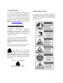
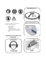
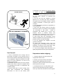
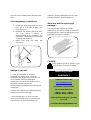
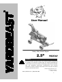
©
User Manual
Heavy Duty Wood Chipper
2.5”
YB2510
WARNING
Read and follow all instructions in this manual before attempting
to operate this machine. Please keep this manual available for
consultation at any time. Read it thoroughly and become familiar
with the operating instructions, maintenance and security
indications. Failure to follow these instructions can result in serious
injury to yourself and others.
www.yardbeast.com | (305) 396-3396
Rederick Metal Industries Corp.
1925 NW 21st Terrace
Miami, FL 33142
1
THANK YOU!
INDEX
We are very grateful that you have
purchased a wood chipper manufactured
by us. The same has been designed and
carefully fabricated to give you excellent
performance, great reliability and exceed
your expectations.
Important safety measures……………....3
Please read carefully and follow all the
instructions in this manual before operating
this wood chipper. This manual tells you how
to set up, operate and maintain this
machine safely and easily. Make sure to
follow all recommended safety measures,
and instruct any other person operating this
chipper. Failure to comply, could result in
personal injury to the operators and others.
All information contained in this manual
refers to the latest product information
available at the time of printing. It is
recommended that you review the manual
frequently to familiarize yourself with the unit,
operation and its features.
We are developing and improving our
equipment continously (Kaizen); if you have
a problem, doubt, or if any information in this
manual does not match what is on your
wood chipper, don't hesitate to your dealer
or authorized service representative, or any
case please contact us directly. The phone
numbers, web site and mailing address of
Rederick Metal Industries Corp. are located
on the next page. In the case that your
wood chipper is equipped with an engine;
the engine manufacturer is responsible for all
matters related to the performance, power
output,
specifications,
warranty
and
maintenance of it. For more information see
the Owner’s Manual/ Operator delivered by
the engine manufacturer. This is shipped in
a separate packaging, together with its unit.
Assembly of the 2510…………………..….8
Controls and Features…………………….11
Operation…………………………………...12
Maintenance and Adjustment.........…..13
Servicing..…………………...……………….15
Troubleshooting………………………….…17
Parts Replacement……………….……… 18
Warranty Information………………….…..19
Parts list………………………………………..20
PRODUCT REGISTRATION
Before you assemble and use your new
wood
chipper,
please
locate
the
information plate on the unit and record the
information in the boxes located at the
bottom of this page. The plate is located in
the lower left part of the machine on the
feed hopper side. If you have to request
technical support via our web site, phone
customer support, or a dealer/servicing
dealer, you will need this information.
MODEL NUMBER
SERIAL NO.
2
CUSTOMER SUPPORT
In case you have problems to assemble this
wood chipper or have questions with regard
to the controls, operation or maintenance of
the same, you can request assistance from
us. You can choose the options that are
presented below: 1925 NW 21 ST TERRACE,
Miami, FL 33142 /Phones: (305)-396-3396/
web site: www.yardbeast.com
SYMBOL IDENTIFICATION
It is important that the operator understands
the safety symbols that are located in
different places of this wood chipper. Below
are the list of symbols and the information
expressed within.
IMPORTANT SAFETY MEASURES
This machine is designed to be used in
compliance
with
safety
regulations
contained in this manual. As with any type
of motorized equipment, an error or
negligence on the part of the operator can
cause serious injury.
This machine is capable of amputating
fingers and hands; it also expel foreign
objects with great force, that can cause
damage to a person by facial and body
exposure.
In case of any emergency, attempt to shut
off engine and seek immediate help.
The presence of this symbol
indicates that these are important
safety instructions that must be followed in
order to avoid putting at risk your personal
safety and other’s. Read and follow all the
instructions in this manual before operating
this machine.
When you see this symbol:
Keep Warnings in mind.
3
ONLOOKERS AWAY AT:
Wear Ear Protection
Wear Eye Protection
Wear Safety Gloves
30 ft.
No hands beyond
this point
Caution
INSPECT BLADES BEFORE EACH USE
Protective equipment required for the
operation of this equipment.
•Safety goggles
•Safety gloves
• Hearing protection.
• Appropriate outwear(preferably
long-sleeved shirts and trousers for
work)
IMPORTANT FACTS ABOUT THE
EQUIPMENT
USE PROTECTION
2.5”
4
AVOID SLOPES
USE RECOMMENDED TOLERANCE
3/32”
Train Yourself
1. Read, understand and comply with all
instructions included in this manual and in
the machine before assembling and putting
it into operation. Keep this manual in a safe
place for future reference, as well as for
ordering spare parts.
2. Familiarize yourself with all of the controls.
Please know how to stop the chipper when
it is operating and how to manipulate the
controls quickly.
3. Persons older than 16 years of age, must
read and understand the operating
instructions as well as the safety rules
contained in this manual. No persons below
16 years of age should operate this
equipment.
4. Without receiving appropriate instructions,
do not allow anyone to operate this
machine.
5. Do not turn ON the chipper in closed
spaces or in an area with little ventilation.
The gases from the engine exhaust contain
carbon monoxide, a lethal gas which is
odorless.
6. Use appropriate protective equipment in
each operation.
7. Don't put your hands close to the parts
that are in motion or inside the feed hopper
-as indicated in the prints - when in
operation. Be careful not to touch any
surface which is heated during the
operation and remains as such for a long
time after the wood chipper is shut down.
8. Stay away from the discharge, wood
debris is expelled with great speed that can
produce facial or body damage.
9. Do not operate the chipper if its belt
guard is removed.
10. Keep the passersby away from the
chipper while it is running. Do not allow the
presence of minors in the work area. Stop
the machine if anyone enters the area.
11. Turn off the engine and disconnect the
spark plug before servicing the equipment.
Preparations before chipping
1. Carefully inspect the area where the
equipment will be used.
2. Protect your eyes, always use safety
glasses while operating this machine.
Otherwise, objects thrown that bounce can
seriously injure your sight.
3. Use ear protection. This will protect you
from the noise produced by the chipper
when you feed the material into the hopper.
5
4. Use work gloves with palm of leather or
industrial cotton when you feed the material
into the hopper. Before you turn on the
machine, check all bolts and accesories to
ensure that the machine is in safe operating
condition.
5. Perform a visual inspection of the
machine in frequent intervals to check
whether the chippers has suffered any
important damage.
6. Maintain and replace the safety labels
and instructions as necessary.
while the engine is hot or running . Allow
engine to cool at least two minutes
before re- fueling .
7. Never overfill the fuel tank . Fill tank to
no more than 1/ 2 inch below the base
of the neck of the thread to allow room
for fuel expansion.
8. Place the fuel cap back on and
tighten securely .
9. Clean up spilled fuel on the engine
and equipment. Move machine to
another area. Wait 5 minutes before
starting the engine.
Safe Handling of Fuel
To avoid personal injury or property
damage, be very careful when handling
fuel. The fuel that is used, whether diesel or
gasoline is highly flammable and the vapors
are explosive. You can be seriously injured if
fuel is spilled on yourself or your clothes
which can ignite. Wash your skin and
change clothes immediately.
1.Use only containers approved for
Gasoline or Diesel .
2. Never fill containers inside a vehicle or
truck. Always place containers on the
ground away from your vehicle before
filling.
3 . Keep the nozzle in contact with the
edge of the entrance to the engine fuel
tank or container at all times until it is full
at recommended engine manufacturer
specifications.
4 . No smoking should take place. Turn
off all cigarettes, cigars, pipes and other
sources of ignition.
5. Never refuel the machine indoors.
Operation of the Wood Chipper
1.Check the oil and fuel level before
starting the engine.
2 . Do not put hands near rotating parts
or power inputs . Contact with the
chipper and rotating parts –while in
operation- can serioulsy damage fingers,
hands .
3. Before operating the machine , open
it. Check and clean the rotor of foreign
debris objects , make sure the cutting
chamber is empty and free of any
foreign material.
4 . Thoroughly inspect all material to to
be chipped and remove any foreign
objects -such as nails, glass, steel wire,
etc- that could cause injury to you or
damage the machine.
5 . Do not attempt to chop material
larger than specified in this manual. Puts
you and the machine at risk.
6. Keep all guards and safety elements in
place and in good condition.
6. Never remove gas cap or add fuel
6
7. Do not operate this machine while under
the influence of alcohol or drugs.
8. Never operate this machine without good
visibility or light .
5 . Do not change the engine governor
settings or overspeed the same . The
governor controls the maximum safe
operating speed of the engine.
9. If the engine is hot, do not touch as it may
cause severe burns.
6. Maintain or replace safety and instruction
labels as necessary.
10. Do not attempt to move the chipper
while the engine is running .
7. Follow the instructions in this manual safely
storing this machine off season.
11. While feeding material into the machine,
keep your face and body behind the
discharge zone .
8. Never store the chipper or fuel container
in an enclosed space where there is
presence of flame, spark or pilot light such
as water heaters, furnaces, clothes dryers,
etc.
12. Never attempt to unclog the outlet or
discharge opening while the engine is
running. Turn off the engine and wait until all
moving parts are at a complete stop.
9. Allow machine to cool at least 5 minutes
before storing after shutting it down.
13 . If any situations occur which are not
covered in this manual, be careful and use
common sense. Swiftly turn off the chipper
and then contact us for further advise on
your situation.
10. Always refer to the operator manual for
proper instructions for off-season storage.
Maintenance and Storage
12. Observe the rules of proper disposal laws
and regulations for gas, fuel, oil, etc. to
protect the environment.
1.Never tamper with the safety components
recklessly . Check periodically that they are
functioning properly.
11. If you need to empty the fuel tank, do
this outdoors.
DO NOT MODIFY ENGINE
2 . Make sure all screws, bolts , pins and
cotter pins are in good condition to make
sure the machine is in safe operating
condition . Also , visually inspect the chipper
to control if it is damaged and determine if
repair is necessary.
To avoid serious injury, do not
modify the engine in any way. If you change
the engine governor settings, it can get ouf
of control and operate at unsafe speeds
and off-spec. Never change the factory
settings of the engine.
3. Lubricate the bearing often as
maintenance chart (found below) to avoid
wear , it also protects from corrosion and
reduces heat , prolonging its life.
Installation and Setup
4. Before cleaning, repairing or inspecting
the chipper, stop the engine and check all
moving parts have stopped.
1 Wood Chipper
1 Discharge neck
Cage Metal Content:
7
1 Feed hopper.
1 Bag of nuts and bolts that includes:
Bolts, washers, nuts, cotter pins, rotating shaft
hopper clamps, etc.
2 Axles (Rotating, Fixed)
4 Wheels
Manuals and Operator safety accesories.
Assembly of the YARDBEAST 2510
Note: This unit is shipped without fuel and
without oil in the engine. Fill with either diesel
fuel or gasoline (depending on the engine
type) and oil as indicated in the instructions
in the engine manual BEFORE operating your
wood chipper.
4. Remove the grinder removing
platform anchoring ships. See Fig.
the
Taking shipping cage off.
1. Remove plastic packing
2. Unscrew the legs of the cage as shown in
next Figure.
Axle Assembly
1. Inserting front axle and bolt it as shown in
Fig.
a. 4 Hex Bolts 3/8 "x 1"
b. 4 Hex Nuts 3/8 "
c. 4 Pressure Washers 3/8 "
d. Plain Washers 4 3/8 "
3. Remove upwards (use 2 people if
possible) as shown in next Figure.
8
-Inserting rotating axle and boltit as shown in
Figure below.
a. 4 Hex Bolts 3/8 "x 1"
b. 4 Hex Nuts 3/8 "
c. 4 Pressure Washers 3/8 "
d. Plain Washers 4 3/8 "
Pull Assembly
-Next figure shows the assembly of the pull
bar..
-Secure in place using safety cotter pins and
deforming to prevent slipping of the pin.
-Insert tires in their respective shafts
-Place safety pin across each shaft with
pliers and warp them to prevent loosen of
your tires in operation, as shown in Fig.
4- 5/8” Washers
4 Cotter Pins 3/16 "x 1"
Nuts and Bolts: 1/8 "x 1" cotter pins (2 units)
Feed Hopper Assembly
-Assemble the hopper as shown in Fig.
Nuts and bolts:
a. 9-Hex Bolts ¼ "x 1"
b. 9-Pressure Washers ¼ "
c. 9-Plain Washers ¼ "
d. 9-Hex nuts ¼ "
9
Nuts and bolts:
a. 1 Carriage Bolt 1/4 "x 1"
b. 1 Pressure washer 1/4 "
c. 1 Hex nut 1/4 "
Discharge Assembly
1.Locate discharge neck as shown in the
figure and secure it to the chipper.
2.Make sure the carriage bolts are placed
inside out so the head is inside the
discharge.
Nuts and bolts:
a. 2 Carriage Bolts 3/8 "x 1"
b. 2 Pressure Washers 3/8 "
c. 2 Hex nuts 3/8 "
Setting up your Wood Chipper
Fuel & Oil
Read and follow all instructions in the engine
manual for more information on this matter.
Once you have finished assembling your
wood chipper, you must prepare your
engine for the first start. Locate the fuel cap
in the top of the engine and remove it. You
should
fill
the
tank
engine
with
approximately 2.5 liters of clean, fresh fuel.
Pull Holder Assembly
1. Set pull holder as shown in Fig.
2. Secure in place using carriage bolt.
10
ADVERTENCIA
Use
extreme
caution
when
handling fuel. Fuel is highly
flammable and the vapors are
explosive. Never fuel the machine
indoors or while the engine is running or hot.
Extinguish cigarettes, cigars, pipes and other
sources of ignition.
These are some of the wood chipper
features and controls you should be aware
of to familiarize yourself with the chipper.
It is very important you understand its
components for a safe operation of the
machine and further instruct someone else
on the operation of this chipper if needed.
CONTROLS & FEATURES
Engine
Deflector
Manual
Canister
Discharge Neck
Belt Guard
Pull Bar
Feed
Hopper
Anvil
Rotating
Axle
HOPPER: You can allow the entry of wood up to
2-1/2 "diameter in the hopper to be chopped.
Fixed
Axle
WARNING
When operating the wood chipper,
11
use safety protection, this chipper
expels wood chips with great force
by design.
IMPORTANT: Never place wood in the
hopper with a diameter greater than 2-1/2 ".
Doing so could damage the blades and
jeopardize the integrity of the machine.
PULL: The pull is used to manually transport
the chipper to the place of operation. Try to
turn the pull at less than 45 degrees to avoid
any stress on the pin.
and body damage.
OPERATION
Working with your Wood Chipper
The material to be chipped enters the
cutting area through the feed hopper
where this is impacted by a sharp blade,
which together with the anvil, produces
scissor cutting effect. Once cut and
desintegrated by the back flaps,
the
material is radially ejected through the
discharge neck.
Starting your Engine
WARNING
Never run an engine indoors or in
a poorly ventilated area. Engine
exhaust contains carbon monoxide, an
odorless and deadly gas.
To start the engine, please follow these
steps:
ENGINE: See engine operation manual that
came with your unit. This is located inside the
manual holder for the location and
operation of the motor.
1. Turn the fuel valve to the ON position and
the switch in the ON position. (If equipped)
See Fig.
MANUAL CANISTER: Keep the user manual of
the chipper and the engine inside the
manual canister –as well as safety
accessories if needed- for future reference.
DISCHARGE DEFLECTOR: use the discharge
neck deflector to adjust the distance of
discharge of material to be chopped.
WARNING
Use protective gear ,and to
adjust the discharge neck, if this
is done without protection, it can
seriously damage the eyes and cause facial
2. Move the throttle control lever to the
choke position.
See Figure.
12
6. Once the engine starts to run, quickly turn
the throttle lever (choke) to the RUN
position.
7. If for some reason the rotor stops spinning,
the engine loses power but it doesn not shut
down, is because this chipper is equipped
with a centrifugal clutch that only engages
when it passes a certain amount of RPMs.
Turn off the engine (as directed below) and
check what is blocking the rotor.
3.Move the lever throttle control to the fast
position.
See the figure.
4. Firmly hold the handle of the starter rope,
pull the starter cord slowly until resistance is
felt, then pull rapidly.
Stopping your engine
1. Move the throttle lever to the start
position, where it was in the beginning (slow
position).
2. Shut the fuel valve and turn the engine
switch OFF.
MAINTENANCE
General recommendations :
1. Always observe safety rules when
performing maintenance.
2. The warranty on this wood chipper, does
not cover items that have been subjected
to wear, misuse or negligence of the
operator. To receive any warranty benefits;
the operator must have maintained the
equipment as indicated in this manual.
5. If the engine does not start, repeat again
the previous three steps until engine fires.
13
3. All settings (blade, anvil, etc.) should
be checked at least once before
each use.
4. Periodically check all bolts, nuts, safety
pins, etc.
WARNING
Stop the engine and disconnect
the spark plug before servicing
equipment.
Lubrication
1. Lubricate the rotating elements such as
rotor, bearings once a season.
2. Follow engine manual for engine
lubrication instructions.
Wood Chipper Maintenance
Schedule Chart
Before each use
•Check power belt
• Check blade and anvil
Every 25 hours
• Bearings are sealed so they don’t need
lube
• Regrind blade
• Regrind anvil
Engine Maintenance
Use only original spare parts for the engine.
Other parts may not perform as well
damaging the unit; and may cause injury.
Moreover, the use of other parts may void
your warranty.
Exhaust Gases Control
Maintenance, replacement or repair of
devices and emission control systems may
be performed by any manufacturer
authorized establishment for these engines.
Refer to engine manual for more information
or contact us. We will be glad to help.
WARNING
Unintentional sparking can result in
fire or electric shock.
Before making adjustments or repair
into the unit.
• Disconnect the spark plug.
• Disconnect battery at negative terminal
(only engines with electric start).
• Use only correct tools.
• Replacement parts must be the same and
installed in the same position as the original
parts.
• Do not strike the flywheel with a hammer
or hard metal object. Bearings suffer the
load.
When checking for sparks
•Use an approved tester.
•Do not check for spark with spark arrestor
removed.
Engine Maintenance Chart.
First 5 hours of use
•Change oil
Every 8 hours of use
•Check Oil Level
•Clean area around exhaust,controls and air
intake.
•Clean recoil grille
Every 25 hours of use
•Clean air filter**
•Clean pre-filter (if fitted)
Every 50 hours of use
•Change oil
•Replace Oil Filter
•Check muffler and spark arrestor
Annually
•Change air filter.**
•Replace pre-filter (if equipped)
•Replace spark plug
•Clean air cooling components
•Replace Fuel Filter (if equipped)
•Check valve tolerance*
14
** Clean filters and air intakes more often in
dusty conditions or when there is high
density of airborne
* Not required unless engine performance
problems are detected.
intake system to allow proper air
circulation. Remove all grass, dirt
and combustible debris from muffler
area.
SERVICING
Replacing Power Belt
Rotor Blade
1. Stop the engine, disconnect the spark
plug and check that the engine has
stopped completely.
2. Remove the bolts holding the belt guard
and remove.
3. Loosen the bolts holding the engine at its
base.
4. Adjust belt tension by loosening the
ensioner bolt unscrewing basis, use a wrench
9/16 " hex wrench.
5. Proceed to replace and adjust tension
again until it is felt tight by pressing down
with the finger.
6. Bolt the belt guard in the same way it was
disassembled.
Cleaning of the equipment
Carefully clean the cutting chamber after
each use.
WARNING
The rotor blade is sharp. Wear
leather gloves to protect your
hands when cleaning the cutting
chamber.
WARNING
The rotor blade is sharp. Wear
leather gloves to protect your
hands when the cleaning cutting
chamber.
Blade re-sharpening
1. Stop the engine, disconnect the spark
plug and check that the rotor of the chipper
has stopped completely.
2. Open chipper loosening the lock knob.
3. Remove the bolts securing the blade to
the rotor using a 5mm Allen key and a 9/16”
hex wrench.
4. Remove the blade and proceed to
change or blade sharpening.
5. Blade must be sharped at a 30deg. angle
and must not overheat to loose its heat
treatment properties.
6. Tighten the bolts again.
NOTE: Blasting pressurized water is not
recommended.
Taking care of your engine
NOTE: Review the sections of maintenance
and operation of the engine manual for
detailed instructions.
1. Check the oil level.
2. Clean the engine regularly with a
cloth or brush. Keep clean the air
NOTE: To remove the blade’s bolts, it is
recommended to place a piece of wood in
between the rotor and the outside edge to
15
prevent it from rotating when loosening the
bolts.
Anvil sharpening or adjustment
1. Loosen the bolts from under the anvil
bed. Use a 9/16 "Hex Wrench and
5mm Allen key.
2. Between the blade and the anvil,
you must leave a space of
approximately 3/32” (2.38mm). This
clearance is important to ensure best
chipping performance
3. Make sure that the bolts are
tightened.
Anvil
Storage of your unit.
1. Care must be taken to prevent
oxidation on the surfaces. Cover all
equipment with a light coat of oil and use
an oil-soaked cloth for cleaning all
equipment. The cover the chipper with a
big plastic bag to prevent the
environmental conditions from harming the
equipment.
2. Follow the lubrication recommendations
engine for off-season storage.
3. Store equipment in a clean, dry area.
Never store the machine or fuel container
where there is an enclosed space, fire
presence, spark or pilot light such as water
heaters, furnaces, clothes dryers, etc..
What to to with the metal cage
package?
You may modify the box as storage
purposes, or you can cut it with a hand saw
into little pieces. These can disposed in local
garbage afterwards if needed.
CAUTION
Wear leather gloves to protect your
hands when cutting the corners.
Have any more
questions?
Please contact us at:
www.yardbeast.com
(Customer Contact Form)
Or you may call us at:
(305) 396-3396
If you feel like writing us you may
do so at:
[email protected]
16
TROUBLESHOOTING
Problem
Engine does
not start
Low blade
performance
Low engine
performance
Engine
overheats
Engine is
erratical
Cause
Solution
1. The spark plug is disconnected
2. The fuel tank is empty.
3. Shut-off valve is closed.
4. Dirty air filter.
5. The carburetor is dirty.
1. Connect the cable to spark plug.
2. Fill tank with clean, fresh fuel.
3. Turn the fuel valve ON
4. Clean or replace the air filter
5. Take it to the engine manufacturer
authorized workshop
1. The blade is not in correct position.
2. The blade has dull edge.
3. Blade has cracks
1. Check and correct the position.
2. Sharpen the blade.
3. Replace blade.
1. Lack of fuel.
2. The carburetor is dirty
3. Obstructed air filter
4. Loose spark plug cable
1. Fill the fuel tank.
2. Take engine to an authorized workshop.
3. Clean or replace the air filter.
4. Connect and tighten spark plug wire.
1. The engine oil level is low.
2. Restricted air flow.
1. Fill crankcase with proper oil.
2. Remove blower housing and clean.
1.The spark plug wire is loose.
2. Fuel is old.
3. Water or dirt in fuel system.
4. The air filter is dirty.
5. Valve tolerance out of specification.
1.Connect and tighten spark plug wire.
2. Fill tank with clean, fresh fuel.
3. Drain the fuel tank. Refill with fresh fuel.
4. Clean air filter
5. Take the engine to authorized workshop.
17
SPARE PARTS LIST
Component
Part Number and Description
# PART: 251001
| BLADE
# PART: 251002
| ANVIL
# PART: 251003
| KNOB
# PART: 251004
| POWER BELT
# PART: 251005
| CLUTCH
# PART: 251006
| 10-INCH WHEEL
18
Manufacturer’s Warranty
The limited warranty ser forth below is given by Rederick Metal Industries Corp. – towards the YARDBEAST Chippers Outdoor
Power Equipment line, with respect to new merchandise purchased and used in the continental United States.
Rederick Metal Industries Corp. warrants this product against defects for a period of two (2) year commencing on the date
of original purchase and will, at its option, repair or replace, free of charge, any part found to be defective in materials or
workmanship. This limited warranty shall only applyif this product has been operated and maintained in accordance with
the Operator’s Manual furnished with the product, and has not been subject to misuse, abuse, commercial use,neglect,
accident, improper maintenance, alteration, vandalism, theft,fire, water, or damage because of peril, natural disaster or by
acts of God.
Normal wear parts or components thereof are subject to separate terms as follows: All normal wear partsor component
failures will be covered on the product for a period of 90 days regardless of cause. After 90 days, but withing the two year
period, normal wear parts failures will be covered ONLY IF caused by defects in materials or workmanship of OTHER
componentparts. Normal wear parts and components include, but are not limited to: belts, tires, knives, counter knives,
knives adapters, flails, centrifugal clutch and bearings.
How to obtain service: Please contact Rederick MI Corp, Miami FL 33142. For info on how to service your machine contact
us at (305)-396-3396 or write to [email protected] or log on to our website at www.yardbeast.com.
This limited warranty does not provide coverage in the following cases:
a. The engine or components parts thereof. These items carry a separate manufacturer’s warranty. Refer to applicable
manufacturer’s warranty for terms and conditions.
b. Centrifugal damage or components thereof. These items carry a separate manufacturer’s warranty. Referto applicable
manufacturer’s warranty for terms and conditions.
c. Routine maintenance items such as lubricants, filters, blade sharpening, tune-ups, clutch adjustments, and normal
deterioration of the exterior finish due to use or exposure.
d. Rederick MI Corp. Does not extend any warranty for products sold or exported outside the continentalUnited States;
except those sold through authorized Rederick MI Corp. Dealers and/or channels of export distribution.
e. Parts that are not genuine to the Yardbeast Chipper line will not be covered by this or any other warranty expressed by
Rederick MI Corp.
f. Transportation charges and service calls are not covered.
No implied warranty, including any implied warrantyof merchantability of fitness for a particular purpose, applies after the
applicable period of express written warranty aboveas to the parts as identified. No other express warranty, whether written
or oral, except as mentioned above, given by any person or entity, including a dealer or a retailer, with respect to any
product manufactured by us shall bind Rederick Metal Industries Corporation. During the period of the warranty, the remedy
is repair or replacement of the product as set forth above.
The provisions as set forth in this warranty provide the sole and exclusive remedy arising from the sale. Rederick Metal
Industries Corp. shall not be liable for incidentalor consequential loss or damage including, withoutlimitation, expenses
incurred for substitute or replacement lawn care services or for rental expenses to temporarily replace a warranted product.
Some states do not allow the exclusion or limitation of incidental or consequential damages, or limitations on how long an
implied warranty lasts, so the above exclusions or limitations may not apply to you.
In no event shall recovery of any kind be greater than the amount of the purchase price of the productsold. Alteration of
safety features of the product shall void this warranty. You assume the risk and liability for loss, damage or injury to you and
your property and/or others and their property arising out of the misuse or inability to use this product.
This limited warranty shall not extend to anyone other than the original purchaser or to the person for whom it was
purchased as a gift.
This limited warranty gives you specific legal rights, and you may also have other rights which vary from state to state.
19
PARTS LISTT
BASE
No
Components
Part No.
1
Base
251007
2
Live axle
251008
3
Fixed axle
251009
4
Pull bar
251010
5
Belt tensioner
251011
6
Pull Bar Pin
251012
7
Pneumatic Wheel 10” x 5/8”
251006
8
Rubber grip
251013
DISCHARGE NECK
No
1
2
3
Components
Discharge neck
Deflector
Knob
Parto No.
251014
251015
251003
20
ROTOR
No
1
2
Components
Rotor
Blade
Part No.
251016
251001
CHIPPER
No
1
2
3
4
5
6
7
8
9
Components
10
11
Spacers
Bottom
Top
Feed Hopper
Bearing housing
Dirt screen
Anvil
Open/Close Pin
Lock safety tube
Lock safety pin
Knob
Part No.
251017
251018
251019
251020
251021
251002
251022
251023
251024
251025
251003
21
BELT GUARD
No
Component
Part No.
1
Belt Guard
251026
2
Large guard support
251027
3
4
Small guard support
3/8 “ screw bar
251028
251029
5
Nylon safety nut- 3/8”
251030
6
Plain washer - 3/8”
251031
7
Pressure washer – 3/8”
251032
22
NOTES:
23