1
H(PBECiligffi'I'
H(PBECilJ#gd'
lnstructionManual
PN: 481 400'9-00'l
Printedin Chlna
@20028&K PrecisionCorP
22820Savi Ranch ParkwaY
YorbaLinda, CA 92887
USA
T E L :( 7 1 4 )9 2 1 - 9 0 9 5
FAx. (714J921 6422
w.DKpreclslon com
1148 Analog Multimeter
SAFETY
1.
^r wanNthrc
An electrical shock causing 10 mA of current tc pass through
the heart will strtpmost httnan lrcarlbeats. \/oltage as /ow as 35
volts dc or ac rms should be considereddangerotts and hazardotts
sinceit can produca a lethal currcnt under ceftain conditions.
Higher currents are even rnore dangerotts. Observe the following
safety precautions:
"SPECIFICANevorapply inputvoltagesltreaterthan those listedin the
TIONS"section.Personalinjuryor damageto thc instrumentmay occLlr.
i n d r - r s t r ri ar sl e ;f o r e x a m p l e .
2 . T h i s m e t e ri s n o t r e c o m m e n d efdo r h i g hr r o l t a g e
not for measurementsof 440 \1 AC or 600 \/ AC industrialpowe!.mains.The
unit is intendedfor use with low energyoircttitsto /50 V AC or l0fl0 V DC or
l i s u s eb y c o n n e c t i o n
h i g he n e r g yc i r c u i t st o 2 5 0 V D C o r A C . A c c i d e n t am
acrossa high voltage,high energypowersotlrcewhen lhe meteris set rrpfor
mA measurementmay be very hazardous.
3.
Turn equipmentoff beforemakingrest connectionsin high voltagecircuits
power.
Dischargehlgh voltagecapacitorsaftg!"remDVinq
4.
t e a s u r e m e n ti sn h i g hv o l t a g ee q t l i p m e n t ,
W h e n m a k i n gv o l t a g eo r c u r r e n m
nevertouchequipment,meter,or test leadsurhilepower is applied.
5.
b to i n qt e s t e da n d i h e
f i t ht h e e q L r i p m e n
l f p o s s i b l ef,a m i l i a r i zyeo t l r s e lw
locationof its highvoltagepoints.Flowever.remenlborthal hiqh voliagemav
d o i n t si n d e f e c t i v e q r l i p m e r ] l .
a p p e a ra t u n e x p e c t e p
6.
B e c a r e f utl o a v o i dt o u c h i n ga h i q hv o l t a g ep o i n t .R e m e m b e trl l a ta c l i n ev o l f age mav be presentin equipmentundertest (for example,at on-nIfswitch'
to an ac otitlet,
fuses,lransformer.etc.).any time the eqllipmentis connercted
even if it is turnedoff.
7.
When removingthe cover for servicingor batteryreplacernent,removetest
leads and make sure that the inpLttis disconnectedfrom any high voltage.
8.
" o n e h a n di n l h e p o c k e t "t e c h n i q u ew h i l eh a n d l i n ga n
U s e t h e t i m ep r o v e n
instrumentprobe.Be particularlycarefulto avoid contactinga nearbymetal
objectthat couldprovidea good groundreturnpath.
SPECIFICATIONS
When using a probe,only touchthe insulatedponion.Nevertouch the
exposedtip ponion.
1 0 , Use an insula.tedfloor materialor a large,insulatedfloor mat to stand on, and
an insulatedwork surfaceon which to place equipment;make certainsuch
surfacesare not damp or wet.
1 1 . When testingac poweredequipment,rememberthat ac line voltageis usually
presenton some powerinputcircuitssuch as on-offswilches,fuses, power
transformers,etc., any time the equipmentis connectedto an ac out-let.This
is true even if the eouiomentis turnedoff.
12 Some equipmentwith a two-wireac power cord. includingsome with a polar-
ized power plug,is the "hot chassis"type. This includesmost recenttelevisionreceiversand audioequipment.A plasticor woodencabinetinsulates
the chassisto protectthe customer.When the cabinetis removedfor servicing, a seriousshockhazardexistsif the chassisis touched.To make
measurementsin "hot chassis'equipmenl.alwaysconnectan isolationtransformerbetweenthe ac outletand the equipmentundertest.The
BK Precision ModelTR-11 0 or 1604 lsolationTransformer,or Model 1653or
1655AC PowerSupplyis suitablefor most applications.
To be on the safe
side,treat all two-wireac poweredequipmentas "hot chassis"unlessyou are
sure it has an isolatedor eanh groundchassis.
1 3 On inslrumentsor any equipmentwith a three-wireac powerplug,only use a
3-wireoutlet.This is a safetyfeatureto keep the housingor other exposed
elementsat eanh ground.
" C + 2 8" C
Accuracyspecificationsapplyfrom + 1 8 t o
DC VOLTS
'120V'
0-300mV,3V, 12V'30 V'
Ranges:
300v, 1200v
20,000ohmsPervolt
SensitivitY:
t 3oloof full scale
AccuracY:
AC VOLTS
Ranges:
SensitivitY:
i Accuracy@50/60H2:
(t1 dB)
ResPonse:
: FrequencY
bc cuRnelt
j
, Ranges:
' Accuracy:
BurdenVoltage
hrstsratce
Ranges:
Neverwork alone.Someoneshouldbe nearbyto renderaid if necessary.
Trainingin CPR (cardio-pulmonary
resuscitation)
first aid is highly
recommended.
AccuracY:
MaximumOPenCircuitVoltage:
MaximumShortCircuitCurrent:
0-12V,120V,300v, 1200v
9,000ohmsPervolt
t 4% of fullscale
40 Hz to 100kHz
12 V range:
40 Hz to 10 kHz
120V range:
40 Hz to 5 kHz
300V range:
40 Hz to 1 kHz
1200V range:
0-50pA,3mA.30mA,300mA,12A
t 3% of full scale
Lessthan600 mV
RX1,0 to 2 kohms,mid scale20 ohms
RXl0, 0 to 20 kohms,mid scale200ohms
R X 1k,0 to 2 Mohms,midscale20 kohms
R X 10k,0 to 20 Mohms,midscale200
kohms
I 3% of full scale
RXl,Xl0,Xlkranges:3V
R X 10krange:9 V
R X 1 rangei150mA
: 5mA
R X 1 0r a n g e 1
RXlkrange:150PA
R X 10Krange:100UA
d B M E A S U R E M E N (Td B s c a l e )
- 1 0d B t o + 2 3 d B o n 1 2 V A C r a n g e
Ranges.
+ 1 0d B t o 4 3 d B o n 1 2 0 V A Cr a n g e
+ 1 8d B t o 5 1 d B o n 3 0 0 V A C r a n g e
+ 3 0d B o n + 6 3 d B o n 1 2 0 0V A C r a n g e
1 mW across600 ohms
0 dB Reference:
BATTERYTEST (good - bad scale)
1.5 V rangefor batterytesl only
Range:
7.5 ohms
Load:
BatteryDrain:
200mA
TRANSISTORLEAKAGE TEST (lceoscale)
Ranges:
0 t o 1 5 0p A o n R X l k r a n g e
0 to 15 mA on R X 10range
0 to 150 mA on R X 1 range
t 5% of scale arc
Accuracy:
MaximumAppliedVoltage:
3 V, voltagemeasuredon LV scale
TRANSISTORGAIN MEASUREMENT
0 to 1,000measuredon hFEscalewilh
Range:
rangeswitchset to R X 10
t 3% of scale arc
Accuracy:
Test Leads :
Special,supplied
GENERALSPECIFICATIONS
Movement:
Jeweledpivots,50 pA full scale
Scale Length:
3-112inches,mirroredscale
+or-,polarityreversalswitch
Polarity:
Batteries:Two 1.5 V AA and one 9 V
PowerSource:
250 volt ceramicfuse. Not for high energy
OverloadProtection:
powprmeasurementsabove250 volts.
0to+40"C
OperatingTemperature:
D i m e n s i o n(sH: x W x D ) .
5-314"x3-718"x 1-318"(147 x 99 x 35 mm)
11 oz. (308 g) with batteries
Weight:
AccessoriesSupplied: Batteries
Test leads, 1 red and 1 black
Transistortest leads
lnstructionmanual.
OptionalAccessories: Carryingcase, LC-298
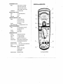
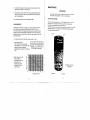
CONTROLSand INDICATORS
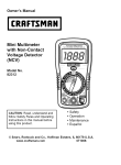
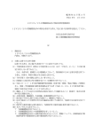
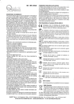
Fig. 1 Controls and indlcators
Scale Mirror
Helpseliminatemeasurementerrorscaused by parallaxwhen viewingscale
OPERATINGINSTRUGTIONS
A
Q Scale
Measurementscalefor resistancereadings.
DCV,A&ACVScale
Measurementscalefor DC volts,DC amperesand AC volts .
BATT. 1.5V Scale
Scale for measuringcondition(good/?/bad)of 1.5 volt batteries.
5.
Be sureto read thoroughtyunderslandand followthe practics
givenin the SAFEW sectionol thismanualto reducethe riskof
electricalshock.
TIPS
GENERALCAREand OPERATING
saction
see the MAINTENANCE
are in goodcondition;
Makosurebatteries
of this manualfor batteryreplacementinstructions
hrr Scale
Scale for measuringtransistorgain.
Alwaysviewthe meterpointerso that its reflectionin the scalo minor ls
parallaxerrors
directlybehindit. Thiseliminates
l c e oL
, V and Ll Scale
Measurementscale for transistorleakage.
Whenthe meterleadsare ramovod,the pointershouldbe al exactzero lf
needed.adjustthe pointerto readzeroby tappingthe meterfacegentlywhlle
zeroscrew.
tha mechanical
adjusting
dB Scale
Measurementscale for decibels(dB).
Function/RangeSelector
Rotary switch to select measurementrange and function.
v.
Awnnltuc
DC+, DC- (Polarity)Switch
Polarityselectorfor DC voltageand current.
The greatestaccuracyis achievedwhenreadingsare in the upperpartof the
melerscale.As a generalrule,selectthe nextlowerrangewhenrsadlngs
are lessthanhalfscale.
set the Functlon/Rangeswltchto
yourmeasurements,
Aftercompleting
ACV and removeleadsfromthe meter.Neverleavethe Functlon/Range
switchin the Q Dositionto conservebatterypower.
1 0 .0Q .ADJust
Zero ohms adjust beforetaking resistancemeasuremenls(leads shorted).
1 1 . C O MJ a c k
Inputfor black, negativepolarity(common or reference)test lead.
12. VQmAJack
Inputfor red, positivepolarity,test lead for most measurementsexcept
12 A range.
1 3 . D C 1 2 AJ a c k
Red, positivepolaritytest lead input for current measurementsup to 12 A.
14. Meter Zero
Mechanicaladjustmentto set pointerof meter to exact zero positionwhen
power is off.
6
DC VOLTAGEMEASUREMENTS
N tout'o*
Nevdr try to measure voltages greater than 120o v. Higher voltages
could damage the meter and/or increase the risk of electical shock
To prevent instrument damage. always set the Function/Range
selector to a rango highor than the maximum voltage you expect
to measure. ff the voltage is unknown. staft with the highest range'
jack
1 Plug black test lead into the COM jack and red test lead into the VQmA
Set Polarity selector to DC+ or DC - as determined by polarity of voltago
vou intend to measure.
RESISTANCE
MEASUREMENTS
3 Set Function/Range switch to desired V:
select1200V.
range. lf range is unknown,
CAUTION
4. Connect black test lead to point of reference (common), red test lead to
desired measuring point. The common should never exceed 600 V
(DC + AC peak) with respect to earth ground.
5. Read voltage at related scale. For best accuracy, try to get a reading of al
least 1/3 scale deflection.
Never apply a voltage to the input terminals when the reslslance
function is selected to avoid damage to the meter. Before taking a
resisfance measurement, make sure circuit under test is elect"cold", power
rically
off and any capacitors discharged.
*
Plug black test lead into the COM jack and red test lead into the VOmA jack,
)
1
Sel FunctionlRangeswitch to desired ohms/resistancerange.
AC VOLTAGE MEASUREMENTS
3.
Shonleads together firmly and verify that pointer rests on exact zelo ohms
lf needed, adjust the 0c, ADJ control to assure poinler rests on zero Repeal
this check each time range is changed. lf pointer cannot be zeroed, one or
both batteries may be weak See the MAINTENANCE section of this manual
to check and/or replace the batteries.
4.
Connect test leads across component or circuit being measured. Obtain
correct resistancevalue by multiplyingscale reading by X lactor
(X1/X1o/etc) of range selected For besl accuracy, select a range that gives
a reading as close as possible to the zero end of the scale.
CAUTION
Never try to measure voltages greater than 12OOV. Higher voltages could damage the meter and/or increase the risk of electrical
shock.
To prevent instrument damage, always set the Function/Range
selector to a range higher than the maximum voltage you expect
to measure. lf the voltage is unknown, staft with the highest range.
1. Plug black test lead into the COM iack and red test lead into the VCImA
jack.
NOTE
Whenmakingresistance
be awarethatthe open
measurements,
circuitvoltagebetweenthe COM and + terminalsis highenough
to foruard-bias
Thisvoltageis about3V in
typicalsemiconductors.
t h eX 1 ,X 1 0 , X l K r a n g e sa n da b o u tI V i n t h eX 1 0 Kr a n g e .
,
2. Set Function/Range switch to desired V- range. lf range is unkndwn,
select1200 V.
3. Connect black test lead to point of reference (common), red test lead to
desired measuring point. The common should never exceed 600 V
(DC + RC peak) with respect to earth ground.
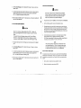
DIODETESTS
I OUT-OF-CIRGUIT
i||
I
i
4. Read voltage at related scale. For best results, try to get a reading of at
least 1/3 scale deflection.
'
I
fh" resistance function of this meter can be used to check the forward/reverse
"
"
resistance ratio of diode devices. This is not a fool-proof test, but it's reasonabty reliable in most cases Also, see Transistor Tests for more semiconductor
checks.
'l
.
2.
Remove diode or similar device beinq tested from circuit.
Select desired resistance range, typically Xl K.
3. Connecttestleadsacrossdiode,thenreverseconnections
Resistance
ratio
shorrldbe at least10,000:1.
nearinfinl$in one directionand low resistance
in otherdirection.
. lf meterreadingis nearinfinitvin bothdirections,
the diodedeviceis
probablyopen.
. lf meterreadingis verylow in bothdirections,
the diodedevicois probably
shorted
Bad / good Judgment
. Transislorbad,open:Zero(0) readingin bothstates,with baseopenor closed.
. Transistor
bad,collector-to-emitter
short:Highreadingin bothstales,withbase
oDenor closed.
Note
Germanium
Transistors
Note:The leakagecurrentin thesetranslstors
alwaysflows
lo the collector.
Thiscausesan errorin the amplification
factorreading.To
compensate
forthiserror,subtractthe readingon the ICEOscalefromthe reading
on the hFE scale.
TRANSISTOR
MEASUREMENTS
Thismeterprovidosthreetransistor
measurement:
leakage.amplification
factorand
had/good
condition.
Thesemeasurements
are madewiththe useof transistor
test
socl<bi,
i6distancofunctionandtrensistor
scalesof thismeterBothNPNand PNP
transistors
can be testsd.
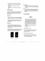
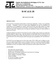
DC CURRENTMEASUREMENTS
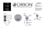
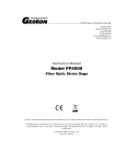
TranslstorhFEtest
lNwrnuue
1. Sqi the Functlon/Range
selectorto R X 10,withtwo testprobeplugodin COMand
VQmA jack, short the leads and maks 0 ohm adjustmentwith 0OADJ knob.
2. IfyouaretestinganNPNtransistorinsertthetransistortolowerthreeholesofthe
socketwith blackmarklngNPN.as the fig.2shown,andget readingon blushre
scale:lt readslc/le= hrr
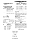
Translstor lcEo test
1. Settho Function/Rango
selectorto a appropriato
O range,makezeroohnrn
ad.justment,
insertthe C and E leadsto the transistor
testsocket,as shownin Fig,3,
readthe leakagecurrentvalueon Ll scaleaccording
to the shortcircuitcurrentof
variousresistance
range.
, 1
2. The lceocouldalsobe measurcdby usingtestleadsin-qtead
of tostsockol.Contacl
Black probeto C laadof NPNtransistor
or E of PNPtransistor,
and conneclRed
probeto E of NPI'lor C of PNPtransistor,
alsoreadlceoon Ll scare.
Plugblacktest leadintothe COMjack.
q
:2
Plugrestlest leadintoappropriate
jack for currentlevelthatyou intendto
measure.Use the DC+'l2Ajack for currbntlevelsgreaterthan0.3 A
(300mA) but notexceeding12 A.
I
13,
Set the FunctionlRange
switchto appropriate
range.
4
Fig. 2 hre test
. Alwaysconnectmeterin seies with load whenmeasuing cumnt.
lf you incorrectly connect it in parallel with the load. it provides a low
impedancepath, almosta short.shuntingtho load. Thishigh
cunentpath coulddamagethe metorand/orequipmentunder tost.
. Alwaysselecta rangehigh enoughto passthe cunentyou plan to
measure.lf currentvalueis unknown,or in doubt. staftwith the
+ 12V range.Neverexceedthe currentrange selectedor range of
the relatedjack.
. Only use thismeter to measuredc cunents:never try to useit to
measureac curent.
"cold".Open
Removepowerfromcircuitundertest.it mustbe electrically
circuitat a pointthatdoesnot exceed600 V (DC+ AC peak)fromearth
ground,or chassisof the equipmentundertest.
Fig.3 lceo test
10
1'!
MAINTENANCE
5. Connectmeterin serieswithlineopened;red test leadto positive(+) side,
blacktest leadto negative(-) sideof this line.
6
zNwanrurrue
Applypowerto circuitand obtaincurrentvalueby readingrelatedscaleal
meter.For bestaccuracy,makesure rangeselectedgivesa readingof at
least1/3scaledeflection.
To avoid personal harm and/or damage to the equipment. remove test
leads before changing batteries, or fuse, or servicina meter.
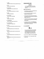
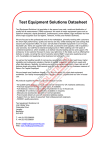
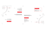
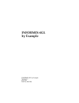
BATTERY REPLACEMENT
7. Turnpoweroff and restorecircuitto its originalcondition.
This meter uses three batteries:two .l.5V "AA,' batteries for the Xi
, X10, X1 K
ranges and one I V bailery for the X l 0K range. The Fig.4 below snows
the location of the batteries and two prolective fuses.
Test batteries when you are near the full adjustment limit of 0e ADJ in
any of the
resistance ranges. Be sure to replace low or discharged batteries prompfly.
Low batteries leak corrosive acid.
dB MEASUREMENTS
ThedB functionof thismeteris actuallyan ac voltagemeasurement
scaledto
readin dB. ZerodBm,labeledas 0 dB at this meter,equals07746V rms
(1 mW into600 ohms).lf lhe measurement
is takenacrossan impedanceother
than600 ohms,use the followingtableto determinethe metercorreclionfactor.
Algebraically
add the correction
factor(in dB) to the meterreading(in dB) for the
correctvaluein dBm.
6F22 9V
1. Connectblacktest leadto COM iackand red test leadto + iack.0
2. Select the desked ACV
range. The dB scale is calibrated for a
direct reading on the 12 VAC range. Other
ranges can be used by adding an
appropriate factor as shown in the following
cha rt.
3. Readvalueshownon dB
scaleand add any
compensation
factorsas
determined
by your
operatingrangeand/or
impedanceif its value
is not 600 ohms.
ACV RANGE
A D Dd B
1 )
0
120 300 120(
2 0 28
40
ACV/dBRangeCompensation
o 2 0
.E
c
ln
a
o
n
Fig.4 Batteryand fuse
reptacement
O,rn
o
o -?o
-30
F 0.5A,/250V
12
F't2N250V
t.)
1. Removerearcase,heldby two Phillipsscrews
then removebatteriesand replace
of batteries,
2. Notepolarityand arrangement
cover.
H(PffiCisffFg'
3. Plugblacktestleadinto coM jack,redtest lead intoVCImAjack.
B&K PrecisionCorp.warrantsto the originalpurchaserthat its product
and lhe componentpartsthereof,will be freefromdefectsin workmanship
and materialsfor a periodof one yearfromthe dateof purchase.
"AA"batteriasDiscardand replaceif
to BATT.1.5V to test
4, Set Function/Range
be sureto replaceboth
pointerrests in BAD or ? areaof scale.Whenreplacing,
Rangeto DCV,12 V to test9 V battery'Discardand
of set. Set Functioni
batteries
replaceif pointerreadslesslhan I V.
B&K PrecisionCorp.will,withoutcharge,repairor replace,at its
option,defecliveproductor componentparts.Returnedproductmustb€
accompaniedby proofof the purchasedate in the form a salesreceipt.
replacecoverandsecuringscrews.
5. Afterseruicing,
To obtainwarrantycoveragein the U.S.A.,thisproductmustbe registered
by complelingand mailingthe enclosedwarrantycardto:
F U S ER E P L A C E M E N T
and a 12N250V5 x 20 mm fuse.lf the
by a Fast0.5A,/250V
Thismeteris protected
the fuseis probablyblown.To replacethefuse' removerearcover
meteris inoperative,
whichis heldby two Phillipsscrews.Onlyreplacefusewiththe originaltype
TESTLEADS
or broken
examinethe testleadslo ensuretheyare not intermittent
Periodically
Also,makesurethatgoodcontactpressureexistsbetweenthejack and receptacles.Keeocontactareascleanandfreefromdirt.
B&K PrecisionCory.,22820 Savi Ranch P'arkwayYorba Linda, CA 92887
withinfifteen(15) daysfrom proofof purchasedate.
Exclusions:Thls warranty does not apply in the event of misuse
or abuse of the product or as a result of unauthorizedalternaflons
or repairs.lt is vold lfthe serial number ls alternated,defacedor
removed.
B&K PrecisionCorp.shallnot be liablefor any consequential
damages,
includingwithoutlimitationdamagesresultingfrom lossof use. Some
statesdo nol allowlimitationof incidentalor consequential
damages,
so the abovelimitation
or exclusionmay not applyto you.
This warrantygivesyou speciflcrightsand you may haveotherrights,
which vary from state{o-state.
ModelNumber
14
Date Purchased:
15
H(PffiCiffi'
ServiceInformation
WarrantyServlce:Pleasoreturnthe productin the orlglnalpackeglng
wlth proofof purcheseto tho belowaddress ClearlystateIn writlngthe
and accessories
probl6mand returnany l6ads,connectors
parformanc€
thatyou ara uslngwlththe devlce,
Non-WarrantyServlce:Raturntha productIn the orlglnalpackaglngto
tha belowaddi6s9.CloerlystateIn wrltlngih€ perfolmancaproblemand
thatyou are uslngwlththe
end accessorlos
returneny l6ads,connectors
noton opanaccountmustInclud€paymont
devlce.CuEtomers
In th€ formof a mon6yord6for credltcard.Forthe mostcunentrepair
chargeBcontactthe factoryboforeshippingthe product.
to B&KPreclslonCorp wlthpre'paldshlpplng.
Returnall merchandlse
Thoflat-retsrepalrchargeIncludesrelurnshlppingto locatlonsln North
Americashlppingfees
and non-North
Amerlca,For overnlghtshlpments
contactB&KProclslonCorP..
B&K PreclBlonGorp.
2282OSavi Ranch Parkway
Yorba Linda, CA 92887
Phone: 714-921-9095
Facsimile:714-521-6422
Email:[email protected]
Includewlth the Instrumentyour completereturnshlpplng
address,contact namo,phone number and descrlptlonof problem.
22820 Savi Ranch ParkwaY
Yorba Linda, CA 92887
Tel: 714-921-9095
Fax:7 14-921-6422
16