1
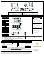
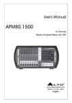
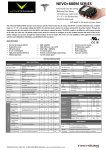
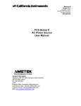
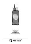
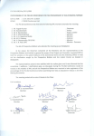
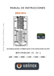
NEVO+ 600 series Installation Manual PLEASE READ THIS INSTALLATION MANUAL CAREFULLY BEFORE INSTALLING THIS PRODUCT AND KEEP THIS MANUAL FOR FUTURE REFERENCE. IMPORTANT INSTALLATION NOTES This power supply is intended for use within equipment or enclosures which restricts access to authorised personnel only. The instructions in this manual and all warning labels on the product must be followed carefully. WARNINGS HIGH VOLTAGE WARNING: Dangerous voltages are present within the power supply. Covers may only be removed by qualified personnel when the power supply has been disconnected from the mains supply voltage for more than 3 minutes. Covers must be replaced and all screws secured properly before reconnecting to the mains voltage. SAFETY The NEVO+ 600S is designed in accordance with safety requirements for UL60950‐1, EN60950‐1, IEC60950‐1, CSA22.2 no. 60950‐1 and LV Directive 2006/95/EC. FUSING WARNING: The NEVO+ 600M is designed in accordance with safety requirements for UL60601‐1, EN60601‐1, EN61010‐ 1, IEC60601‐1, IEC61010‐1, CSA22.2 no 601‐1 and LV Directive 2006/95/EC. To ensure continued protection against risk of fire fuses must be replaced with the same type and rating of fuse. Replacements should be carried out by qualified personnel only. All power supplies must be installed correctly in a controlled environment which restricts access to any unauthorised personnel. Equipment and system manufacturers must protect service personnel against unintentional contact with the output terminals. DERATINGS SPECIFICATIONS Temperature ‐ Input and output power must be derated by 2.5%/°C above 50°C. Input Voltage ‐ Input and output power must be derated by 0.95% / Vrms below 120Vrms (600W @ 120Vrms, 486W @ 100Vrms, 429W @ 90Vrms) Always remember to take the appropriate deratings into consideration before specifying any power supply for an application. If in doubt contact Vox Power. HAZZARDS INPUT ELECTRICAL – NEVO+ 600 Parameter Details Min Max Units AC Input Voltage AC Input Frequency DC Input Voltage Nominally 100Vrms to 240Vrms Standard Medical 600 watt output at 120Vrms Fast acting 85 47 120 120 264 63 370 300 600 6.5 8 Vrms Hz Vdc If series and/or parallel combinations of outputs exceed safe voltage and/or energy levels, the final equipment manufacturer must provide appropriate protection for both users and service personnel. Power Rating Watts Input Current Amps Fusing Amps NOTES: 1. NEVO+ 600 inputs can only be used with NEVO series output modules and must not be used for any other purpose. 2. Use only a power source of the type indicated on the product label for the NEVO+ 600 inputs. 3. For installation relating to UL60601‐1 (Medical) a suitable fuse as described above must be provided in line with the Neutral inlet. 4. The NEVO+ 600 input module is supplied with an integrated fan. Ensure that the inlet and outlet ventilation holes are not obstructed. Ensure there is adequate ventilation provided in the enclosure wherein or near which the power supply is mounted. HEALTH AND SAFETY To comply with section 6 of the health and safety at work act, a label that is clearly visible to service personnel must be placed on the final equipment, which warns that surfaces of the power supply may be hot and should not be touched when the product is operating. FUSING The power supply has internal single pole fusing in the L (Live) line. SERVICING The power supply contains no user serviceable parts. Repairs must be carried out by authorised personnel only. Contact Vox Power Ltd for further information. OUTPUT ELECTRICAL Output Vmin Vnom Vmax Imax Pmax Ppk (4) 1 1.5V 5V 7.5V 25A 125W 187.5W (4) 2 4.5V 12V 15V 15A 150W 225W (4) 3 9V 24V 30V 7.5A 150W 225W (4) 4 18V 48V 58V 3.75A 150W 225W 5 (Dual) 5V 12V 15V 5A 75W (x2) 75W (x2) 6 (Dual) 1.8V 3.3V 5V 5A 25W (x2) 25W (x2) 7 (Dual) 1.8V/5V 3.3V/12V 5V/15V 5A 25W/75W 25W/75W NOTES: 1. NEVO output modules can only be used with NEVO 600 and NEVO+ 600 input modules and must not be used for any other purpose. 2. Take care when removing or adding output modules from the NEVO+ 600 input so that components are not damaged in the process. 3. When the output voltage is adjusted upwards, the output current must be decreased proportionally so that the unit does not exceed the Pmax average power rating as stated in the table above. 4. Peak power up to Ppk is available for not more than 5 seconds at a maximum of 50% duty cycle. The maximum rated average power must not be exceeded. Please refer to the full datasheet and user manual for more information on using the Ppk feature. APPROVAL LIMITATIONS – NORTH AMERICA When this product is used with 180VAC–253VAC mains where no neutral is present, connect the two live wires to L (Live) and N (Neutral) on the input connector. COOLING For proper cooling of the power supply, the air intake and outlet must not be impeded. Allow 50mm clearance at both ends and position cabling appropriately. EARTH TERMINAL MARKING To comply with the requirements of UL60950‐1, EN60950‐1, IEC60950‐1, CSA22.2 no. 60950‐1, UL60601‐1, EN60601‐1, EN61010‐1, IEC60601‐1, IEC61010‐1, CSA22.2 no 601‐1 where the incoming wiring earth is intended for connection as the main protective earthing conductor and where the terminals for such a connection is not supplied on a component or subassembly such as a terminal block, the user shall add an appropriate label displaying a protective earth symbol in accordance with 60417‐2‐IEC‐5019 directly adjacent to the terminal. The label should be durable and legible and should withstand the 15s rub test as per UL60950‐1 section 1.7.15. ENVIRONMENTAL Parameter Details Min Max Units Storage WARRANTY Temperature Humidity Altitude Air Pressure Humidity Altitude Air Pressure Noise Level Shock Vibration ‐40 Relative, non condensing 5 ‐200 54 Full Power ‐20 Derate input and all outputs at 2.5% / °C 50 Relative, non condensing 5 ‐200 78 Measured 1m from fan – No Load @ 25 °C 3000 bumps at 10G (16ms) half sine wave 1.5G, 10 to 200Hz sine wave, 20G for 15min in 3 axes 85 95 5000 106 50 70 95 3000 106 41 °C % Metres kPa °C °C % Meters kPa dBA Operation Temperature Contact your sales agent or Vox Power for product repairs. See Vox Power standard terms and conditions for warranty conditions. Vox Power products are not intended for use in connection with life support systems, human implantations, nuclear facilities or systems, aircraft, spacecraft, military or naval missile, ground support or control equipment used for the purpose of guidance navigation or direction of any aircraft, spacecraft or military or naval missile or any other application where product failure could lead to loss of life or catastrophic property damage. The user will hold Vox Power harmless from any loss, cost or damage resulting from its breach of these provisions. PRODUCT LABELS NEVO+ 600M and NEVO+ 600S The external product label contains information relevant to the power system. The label contains input voltage, maximum input current, input frequency, maximum output power, fuse rating and type, serial number, approvals and product part number in format NEVO+ 600o-oooo-ooo. NEVO OUTPUT MODULES SAFETY Parameter Details Min Isolation Clearance Isolation Creepage Leakage Current Input to Output Input to Chassis Output to Chassis Output to Output Primary to Secondary(Reinforced) Primary to Chassis (Basic) Primary to Secondary(Reinforced) Primary to Chassis (Basic) Standard: 250Vac, 60Hz, 25 °C Medical: 250Vac, 60Hz, 25 °C Isolation Voltage Max Units 4000 1500 250 250 Vac Vac Vdc Vdc mm mm mm mm uA uA 7 2.5 12 4 1500 300 Each output module label contains information relevant to that particular output. The label contains voltage adjustment range, maximum output current, serial number, approvals and part number in format OPo. OTHER A label warning that external surfaces are hot during operation and that the unit should be allowed to cool down properly should be placed on the unit where such a label is clearly visible. The NEVO+ 600 range is designed to comply with EMC standards but it does not imply that the end system will comply. To prolong the life of the unit use in dust free environment. Units can be damaged during transit. Contact your sales agent or Vox Power and DO NOT apply power to the unit in case of transit damage Always use adequately sized cables and ensure good crimp connections. Use cable supports to minimise stress on connectors. Avoid excessive shock or vibration. GENERAL INSTALLATION Parameter Details Parameter Details Equipment class Installation category Pollution degree Material group I II 2 IIIb (indoor use only) Flammability rating IP Rating RoHS Compliance 94V‐2 IP 10 Yes Parameter Details Size 77.7mm x 133.7mm x 41.0mm (all external dimensions ± 1.0mm) 400 grams + 60 grams per output module Bottom or Side mounting (See diagram details) MECHANICAL Weight Mounting Vox Power Ltd. Unit 9 Robinhood Business Park Robinhood Road Ballymount, Dublin 22 Rep. of Ireland Tel: +353 1 426 4930 Fax: +353 1633 5511 Email: moreinfo@vox‐power.com DIMENSIONS AND MOUNTING Fixings Details Mounting MH1, 2, 3, 4, 5 Mounting screws Outputs Cover Fan Output Mounting screws Top Cover Mounting screws Fan Mounting screws Quantity Type Bottom – 3 Side – 2 2 per Module 5 2 M4 – Note: Maximum penetration depth is 4.00mm including chassis M3 x 5, Posi, CSK M3 x 5, Posi, CSK M3 x 24, Posi, CSK Torque 1.50Nm 0.75Nm 0.75Nm 0.75Nm CONNECTORS AND PINOUTS PINOUTS Circuit 1 Live 2 Earth 3 Neutral Circuit 1 PG 2 Inhibit 3 PG 4 Inhibit 5 PG 6 Inhibit 7 PG 8 Inhibit 9 Global Inhibit 10 AC OK 11 +5V 200mA Bias supply 12 J1 Details COM J2 Details Slot A Slot B Slot C Slot D J3 Positive Output Circuit # 2 Circuit # 1 J4 Negative Output Circuit J5 Details 1 ‐ Sense 2 + Sense 3 Voltage Control 4 Current Control/Share/Out 5 COM 6 +5V 10mA Bias supply INTERNAL CIRCUITRY Details J2 + - INHIBIT POWER GOOD AC OK REF. DETAILS MANUFACTURER HOUSING TERMINAL J1 Mains Input: 3 Way, 5.08mm with friction lock, 18‐24AWG Molex(2) 010013036 8701031 J2 Global Signal: 12 Way, 2.00mm, 24‐30 AWG Molex(2) 511101260 503948051 J3/J4(1) Output Power tab: Tab size 6.35mm x 0.80mm Various(2) VARIOUS J5 Notes: Output Signals: 6 Way, 1.25mm with friction lock, 28‐32 AWG Molex(2) 1. Terminal and wire current rating must exceed maximum short circuit output current. E.g. Output 1 = 25A * 1.25 = 31.25A 2. Direct equivalents may be used 3. All cables must be rated 105 °C min, equivalent to UL1015 1510210600 50058800 PART NUMBERING SYSTEM NEVO+ Power series M ‐ 1 1 2 3 ‐ 0 0 0 Leakage Current S ‐ Standard M ‐ Medical Slot A – Output # Slot B – Output # Factory Use Use ‘0’ for unused slots. Blanking plates will be inserted at factory Slot D – Output # Slot C – Output # NEVO+ 600 When initially ordering non‐nominal voltage settings add “ /Voltage” after each output # where a special voltage setting is required E.g. If 3.30Vdc is required in slot B and all other slots require nominal voltages then use: NEVO+ 600M – 1 – 1/3.30 – 2 ‐ 3 The factory will then issue a 3 digit code for your specific configuration that can be used for all future orders of the same configuration When ordering an input unit with no outputs inserted, simply order NEVO+ 600M or NEVO+ 600S Vox Power Ltd. reserves the right to change or improve any part of the specification, electrical or mechanical design or manufacturing process without notice. Please consult your local distributor or contact Vox Power to ensure that you have the latest specification before using your product. For other information relating to the use of the product please refer to the latest NEVO+ user manual. Vox Power reserves the right to make changes without notice to any of its products. Vox Power does not assume any liability arising out of the use or application of any of its products and of any information to the maximum extent permitted by law. No license, express or implied, by estoppel or otherwise, to any intellectual property rights is granted by this document or by any conduct of Vox Power. VOX POWER DISCLAIMS ALL WARRANTIES AND REPRESENTATIONS. IN PARTICULAR ALL OTHER WARRANTIES, CONDITION OR TERMS RELATING TO SUITABILITY, FITNESS FOR PURPOSE, MECHANTABILITY OR CONDITION OF THE PRODUCTS AND WHETHER EXPRESS OR IMPLIED BY STATURE OR COMMON LAW OR OTHERWISE ARE EXCLUDED. Document DOC6009 rev 03 Vox Power Ltd. Unit 9 Robinhood Business Park Robinhood Road Ballymount, Dublin 22 Rep. of Ireland Tel: +353 1 426 4930 Fax: +353 1633 5511 Email: moreinfo@vox‐power.com