1
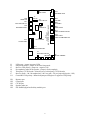
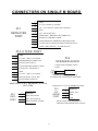
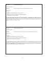
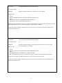
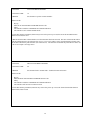
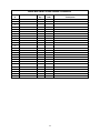
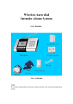
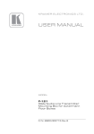
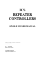
ICS
REPEATER
CONTROLLERS
SINGLE M USER MANUAL
INTEGRATED CONTROL SYSTEMS
1613 Bonnie Avenue
Dixon, IL 61021
Voice 815-284-6963
Fax
815-288-0718
Website www.ics-ctrl.com
Last updated 01/08/2005
Single M User Manual V1.07
TABLE OF CONTENTS
PAGE NO.
Table of contents
1
Overview of the ICS Single M Repeater Controller
2
General Description of the Single M repeater controller
3
Special Features of the Single M
4
Command Structure
5
Quick connect for the control receiver
6
Quick connect for the Repeater to the Controller
7
Specifications
8
Jumper and Plug position diagram
9
Single M board layout diagram
10
Plug wiring diagrams
11
Function numerical list
12 - 13
Function descriptions
14 - 41
Repeater control codes table – use to record your DTMF codes
Single M schematic diagram
Single M User Manual version 1.07
1
42
Overview of the ICS Single M Repeater Controller
Sin·gle m1 or M (sing'g?l (em)) A single port repeater controller designed for the Motorola Micor Mobile.
The ICS Single M repeater controller was designed by a team of experienced Motorola Micor technicians to allow a
single board solution for controlling a Motorola Micor Mobile radio set when converted for repeater service. The
concept of the Single M is a repeater controller with all of the necessary circuitry to allow for the removal of the
control head while still providing complete control of the radio, along with several additional features. These
additional features include onboard Volume and Squelch Controls, PTT Switches for enabling and disabling the
transmitter, and onboard Audio Power Amplifier capable of driving a test speaker. The controller mounts directly
into the Micor Mobile on metal fingers that protrude into the area above the central interconnect/control board, near
the rear of the radio set, on the component side. This area was originally designed to hold the Positive Ground
Converter; which if installed, is removed in repeater duty. The controller can be installed in any Micor mobile
regardless of band or specific style; IE: Railroad, EMS, etc. You only need to remove the black plastic block from
the end of the Micor so the controller will have enough room to mount on the tabs.
The Single M repeater controller is based on our popular BASIC controller, but to include features and support
circuitry necessary for proper interfacing to the Motorola Micor Mobile. The BASIC has a proven track record of
stability and usefulness, and these strong points are the backbone of the operating system design. The additional
circuitry of the ICS Single M insures proper audio and logic interfacing, as well as proper duplex operation of the
Micor Mobile. The circuitry of the controller also provides tools for testing the repeater for desensitization
(desense).
In some instances the original equipment audio power amplifier (audio PA) will not function properly when the
transmitter is on. The audio PA in the Micor Mobile was never designed to operate in duplex mode, and is one
reason why the Single M provides a stable audio PA capable of driving a test speaker; no matter if the transmitter is
on or not. While the controllers’ amplifier produces less than .5 watts of audio power, it’s plenty to drive a test
speaker. This amplifier is unconditionally stable into any load impedance 8 ohms or greater; even no load at all.
The Volume Control only adjusts the audio level to the local test speaker; it doesn’t affect repeat audio level. This
onboard power amplifier allows the repeater builder to remove the Micor Audio Power Amplifier (transistor
assembly), if desired. Doing so greatly reduces power consumption of the repeater by increasing its overall
efficiency, allowing it to be run from batteries or solar/wind assisted power supplies.
The custom support circuitry of the ICS Single M controller ensures no loading of critical parts of the Micor radio,
like the receiver discriminator and COR/PL signals. The Single M provides buffers for these signals so the
associated radio circuitry operates well within the OEM specifications. This translates into the best audio
throughput and complete reliability of the logic controlling the repeater.
The repeater builder has a choice of using the Original Equipment PL (CTCSS) Tone decoder, or a third party unit
like the Communications Specialists (aka: Com-Spec or CSI) TS-32, TS-64, or TS-64DS. Operationally, there is
little difference in the two systems, as both will properly decode a PL tone, but, how the controller handles the logic
from either is different. The design team wanted the ability to use either the OEM Micor or Com-Spec units, and the
controller will accommodate either. This is done with a jumper selection (J5) on the Single M controller board.
With J5 installed, the Single M controller will work with the Com-Spec TS-64, 64DS, and older TS-32 tone units.
With jumper J5 out, the controller will work properly with the OEM Micor PL Tone decoder. If PL filtering of the
receiver audio is desired, we recommend the use of the Com-Spec TS-64, as provisions for using its audio filter are
provided. Although the CTCSS port of this controller is specifically designed to fully complement the CSI TS-64, it
should not be considered the only unit that will connect; as any modern CTCSS decoder, encoder or combination
will likely work with the Single M.
While not specifically designed for the Micor Station, the Single M can be installed with only minor changes to the
Station. The Micor Station COS is generated a bit differently from the mobile and doing the following modification
to your Station Audio and Squelch Board allows the Micor Station to deliver the Active Low squelch logic that the
Single M is looking for: <http://www.repeater-builder.com/rbtip/station-a-s.html>
If you choose to do only the COS part of the modification, (and not the muting mod) that will be fine. This will
effectively give you the same squelch logic as a Micor Mobile; and the Single M will operate correctly as designed.
2
General Description of the ICS Single M Repeater Controller
Here at ICS we strive to make products that have new, innovative, easy to use features and excellent quality at a
reasonable cost. We believe the Single M is such a product. The Single M has such innovative features such as a
full featured control receiver input (has priority), programming with actual values (i.e. Hertz, Seconds, wpm) and a
very easy to use 3 level command access feature which has over 45 commands available. It also has microprocessor
support for a CTCSS board, both encode and decode. There is a plug specifically for the CTCSS board. The
CTCSS encode also has an encode hang timer in which the time is programmable. When designing the Single M we
worked hard to provide a product that is easy to use, durable and of excellent quality at a reasonable cost.
The Single M has many unique features. One such feature is the control receiver input. This input is unique in that
it provides a level of control normally only provided on more expensive controllers. It is optional to use the Control
receiver input as the repeater receiver input will provide the full access to control the repeater. The control receiver
gives you control over the repeater even if the repeater’s receiver is inaccessible. The control receiver COS can be
set to trigger between 1 and 9 volts with a positive or negative acting COS input. When the control receiver COS
becomes active all the repeater port DTMF signals are ignored and the Single M only listens to the control receiver
for DTMF codes.
The new Single M CTCSS control feature gives wide ranges of control over CTCSS decode and encode signals.
The Single M gives you DTMF on and off control over CTCSS decode, encode and the encode hang timer. Also the
CTCSS encode hang timer is programmable. The encode hang timer starts from the time the repeater receiver
becomes non-active. This will allow a reverse burst or courtesy tone to be heard after the repeater receiver becomes
inactive.
The ever growing set of easy to use features can be accessed by a secure Setup mode (program mode), a Control
operator mode and a User mode. If desired the Setup mode (program mode) can be accessed only by a hardware
jumper from the factory. A DTMF sequence (up to 10 digits) can be programmed to give access to the Setup mode
if desired. This provides the highest level of security. In the Setup mode (program mode) all the commands are
accessible by DTMF using their 2 digit function code. This makes the controller programming easy. The User and
Control operator levels use from 1 to 5 digits to access these same functions if setup to do so. From 0 to 25 DTMF
codes can be setup for the User and Control operator levels allowing easy programming, total flexibility and an
extremely secure system for controlling the Single M and its functions.
It can be difficult at times to work on a repeater without knowing what the incoming and outgoing signals are doing.
Connecting voltmeters, scopes and other monitoring equipment can sometimes be difficult. We have provided many
LEDs to help make the setup of the repeater easier. The Single M has 6 of them. Most of the input and output
signals are indicated. The controller will also indicate when it recognizes a DTMF code. The LEDs can be disabled
when not being used by selecting the proper jumper position. We have found these indicators to be a big help when
working with repeaters.
The control inputs and outputs of the Single M repeater controller are very simple to use. There are 2 COS inputs, 1
CTCSS input and 2 open collector type outputs. The inputs include a Control receiver COS input, the repeater input
with COS and CTCSS inputs. You may select between the COS and CTCSS or select both for ‘AND’ control.
This allows for the switching back and forth between carrier squelch (COS) and CTCSS (need an external CTCSS
board (CSI TS-64 or other)) for the ‘receiver active’ signal.
The auxiliary output of the Single M is multi featured and easy to use. The auxiliary output can be used for several
different functions. The auxiliary output can send a short pulse or either be locked on or off. The auxiliary output
has a settable timer that can be enabled or disabled. If the auxiliary timer is enabled and you latch on the auxiliary
output, the auxiliary output will turn off when the timer times out. The auxiliary output has a transmitter fan control
which will turn on the fan when the transmitter comes on and then turn the fan off in a programmable time later
using the auxiliary timer. The 2nd open collector output is for the repeater push to talk. All of the inputs are
buffered and the outputs are protected to greatly reduce any chance of damage.
3
SPECIAL FEATURES OF THE ICS SINGLE M
One special feature of the Single M is support for the Com-Spec (CSI) TS-64 CTCSS encode/decode board from a
dedicated CTCSS Port. Although this port is designed for the CSI TS-64 board, it will likely work with many others
as well. This feature includes a separate dedicated plug to support the CSI TS-64 CTCSS board, CTCSS decode
enable, CTCSS encode and an encode hang timer. The CTCSS encode signal can be mixed with the repeater
transmit audio, or used separately. For more information on this feature see the section on the CTCSS
encode/decode control.
One unique special feature of the Single M is the onboard audio amplifier. The onboard audio amplifier is capable
of driving an 8 ohm speaker, has an onboard volume control, and an onboard 1/8” jack for a speaker. There is also a
provision for flat audio or discriminator (pre-emphasized) audio for the audio amplifier.
Two other special features of the Single M are an onboard transmitter disable switch and a force “transmitter on”
push button switch. The transmitter disable switch is an on/off toggle switch on the controller board which basically
disables the PTT output transistor. These features are intended to help make the offline setup of the repeater easier.
The force “transmitter on” switch is a momentary on push button type. This will allow you to activate the
transmitter independent of the controller. This feature is nice when setting up or testing the transmitter or other
equipment.
4
COMMAND STRUCTURE
The command structure of the Single M is easy to use and very versatile. It includes a Setup mode for programming
and 2 levels for the owner programmed DTMF command line (DTMF sequence) control. The levels are the Control
operator mode and User mode. The structure of these levels gives needed security and still provides a very easy
system to setup and program. The Setup mode gives you direct access to all the controller’s functions directly. In
Setup mode the controller’s function codes are entered directly with your DTMF pad. The Control op and User
modes are very similar to each other. To access a command in either of these modes you need to have programmed
a DTMF sequence (1 to 5 DTMF digits) followed by the function in a DTMF memory. When you enter the DTMF
codes in Control op or User mode that are in a DTMF memory the command in the DTMF memory will be called.
A condition code can be added to the DTMF memory to restrict that DTMF memory (and its command) to the
Control op mode only, the command will then not be accessible in the User mode.
The Setup mode (program mode) allows direct access to all the commands. All the commands are activated just by
entering the 2 digit code that represents that command. When the Single M controller leaves the factory the only
way to access this level is with a hardware jumper. It initially can not be accessed any other way. Normally if the
Setup mode jumper is in you are in Setup mode and if it is not in you are not in Setup mode There are two
commands that can be used to enter and exit the Setup mode remotely, they are ‘Exit Setup mode’ and ‘Enter Setup
mode’. The Setup mode can be accessed by putting the “Enter Setup” command in the Control op or User modes
using a DTMF memory. The 1 to 5 digits you program in will give you access to the Setup mode. If you only allow
access to the DTMF code for the Setup mode in Control op mode the Single M can be setup to require up to 10
digits to access the Setup mode, 5 digits to go from the User mode to the Control op mode and 5 digits to access the
DTMF memory you programmed the “Enter Setup” command into. Remote access to the Setup mode is only
available if you make it so.
When the Single M is in the Setup mode (program mode) the Single M uses a special courtesy tone. The courtesy
tone is 3 dits or a Morse code “S” to indicate being in Setup mode. If the repeater is left in the Setup mode and the
repeater can not be physically accessed to remove the Setup jumper the Setup mode can be exited with a 2 digit Exit
Setup function. This is true even if the Setup jumper is still installed.
The Control op mode is intended to give access to control functions that only a few people should have. In the
Control op mode all the preprogrammed DTMF memories are available. In the User mode you can provide limited
access to the DTMF memories. Only the DTMF memories that have not been setup as Control op level, will be
accessible in User mode. Any, some or none of the Single M’s commands can be enabled on this level. You
program any of the functions you want to give access to, and on what level.
To give access to a function in the Control Operator or User modes a DTMF code and function must be entered in a
DTMF command memory. You must be in Setup mode to program a DTMF command memory. To start the entry
use the “ENTER DTMF COMMAND LINE” function (#65). First you select a DTMF memory 0 – 24, then enter
the 1 to 5 DTMF code digits, then indicate if this DTMF command memory is to be only available in the Control op
level and of course the function you wish to give access to (see the ENTER DTMF COMMAND LINE (#65)
function in the function descriptions). All 16 DTMF digits can be used in a DTMF code including A, B, C, D, * and
#. Examples of the DTMF code layout for a few DTMF memories are shown below;
Memory number | DTMF codes, 1 to 5 digits | Control op? |
0
1
2
3
4
5
2 # 0
2 # 1
3 9 0 B #
C
A # 4 B 2
B
N
Y
N
Y
Y
N
Function
33
32
60
61
58
48
(DISABLE TX 1)
(ENABLE TX 1)
(SET CONTROL OPERATOR MODE)
(CLEAR CONTROL OPERATOR MODE)
(ENTER SETUP MODE)
(ACTIVATE KEYPAD TEST)
Any of the functions can be put in a DTMF command memory. There is a chart at the end of this manual that is
similar to the above and can be copied and used to keep track of your DTMF command memory entries. Note: The
Single M controller comes with all DTMF memories empty, you must use Setup mode (program mode) initially for
access to the Single M’s functions.
5
QUICK CONNECT FOR THE CONTROL RECEIVER
NOTE: You do not need to use this input, it is optional, it is only for use with a separate control receiver. If you
do not plan to use a separate control receiver then please skip this page. The repeater receiver port has access to
all the same control functions (the control receiver has priority). Do not connect the repeater receiver to this
input.
1.
If you decide to use a control receiver you should have the control receiver COS and audio signal already
wired to the proper connections according to the plug layout in this manual before you start. It is not necessary
to use the control receiver input or a control receiver to operate the Single M repeater controller.
2.
Make sure the repeater’s transmitter is disconnected or disabled.
3.
Turn the power off
4.
The control receiver input on the Single M repeater can accept a positive or negative going COS signal from the
receiver. To change the control receiver COS polarity just rotate the jumpers 90 degrees.
5.
Turn the power on
6.
On U5 measure the voltage on pin 2 for a positive COS or pin 3 for a negative COS. Adjust R17 (CONTROL
RX COS LEVEL POT) until the voltage reading is in the middle of the COS voltage range.
7.
If you have a oscilloscope available, monitor the signal on U4 pin 3, if not skip to step 9.
8.
Send a DTMF digit through the control receiver. Set R11 (CONTROL RX AUDIO) until you get about a
200mV reading. You should now see the VALID DTMF LED steadily lit up (no flickering).
9.
If you do not have a scope available start by sending a DTMF digit tone through the control receiver.
10. Adjust R11 (CONTROL RX AUDIO) until you see the VALID DTMF LED light up. Try to find a center
point so you are not on the edge of operation.
11. The control receiver should now be ready to perform control functions.
6
QUICK CONNECT OF CONTROLLER TO REPEATER
This procedure is assuming installation in a Motorola Micor Mobile radio set.
While not specifically designed for the Micor Station, the Single M can be installed with only minor changes to the
Station. The Micor Station COS is generated a bit differently from the mobile and doing the following modification
to your Station Audio and Squelch Board allows the Micor Station to deliver the Active Low squelch logic that the
Single M is looking for: <http://www.repeater-builder.com/rbtip/station-a-s.html>
This procedure will help connect the Mobile repeaters signals to the Repeater Port (PL1) of the controller. It is
assumed that you have already performed the duplex modifications to the Micor Mobile and it is working properly
providing duplex audio and logic signals according to the modification. While many modification sites exist on the
internet for the Micor, we recommend this one: <http://www.repeater-builder.com/rbtip/micor-index.html>
1.
Hook Ground to Pin 1. Ground can be obtained from any trace leading to the metal frame of the radio set, or
directly from the minus lead of the RF Power Amplifier.
2.
Hook +12 volts (constant, unswitched) to Pin 2. Power for the controller can be obtained from the positive lead
of the RF Power Amplifier.
3.
Hook Pin 3 to the PTT of the radio set.
4.
Pin 4, Additional Ground.
5.
Pin 5, Hook this to the TX Audio (Mic. Hi) of the radio set.
6.
Pin 6, Hook this to the discriminator emitter follower.
7.
Pin 7, Hook this to the Squelch Wiper connection of the radio set.
8.
Pin 8, COS Signal from Micor Receiver Unsquelched Indicator.
9.
Pin 9, PL Input. This is used with the OEM Micor PL decoder only.
10. Pin 10, Auxiliary/Fan Output. To optional fan control.
11. Make sure the repeater’s transmitter is disabled. This is accomplished by sliding the manual switch on the
Single M to the “PTT Disable” position.
12. Care should be taken when adjusting the repeaters audio in level with R34 (RX 1 AUDIO) so the DTMF
decoder gets a signal which will allow a reliable decoding of any DTMF digits from the repeater’s receiver
13. If you have a scope available, monitor the signal on U4 pin 3, if not skip to step 7.
14. Send a DTMF digit through the repeater’s receiver. Set R34 (RX AUDIO) until you get about a 200mV
reading. You should now see the VALID DTMF LED steadily lit up (no flickering).
15. Adjust R34 (RX AUDIO) until you see the VALID DTMF LED light up. Try to find a center point so you are
not on the edge of operation.
16. The repeater’s receiver should now be ready to perform control functions.
7
SPECIFICATIONS
SUPPLY VOLTAGE
13.8V Nominal
MAXIMUM CURRENT TRANSMITTER PTT OUTPUT
1A
MAXIMUM CURRENT ON AUXILIARY OUTPUT
1A
AC VOLTAGE IN ON REPEATER RECEIVER AUDIO INPUT
20mVpp to 9Vpp
AC VOLTAGE IN ON THE CONTROL RECEIVER AUDIO INPUT 20mVpp to 9Vpp
AC MAX VOLTAGE OUT ON RECEIVER 1 AUDIO OUTPUT
9Vpp
VOLTAGE IN ON THE REPEATER COS
0 to 30V
VOLTAGE IN ON THE CONTROL RX COS
0 to 30V
VOLTAGE IN ON THE CTCSS INPUT
0 to 30V
OUTPUT IMPEDANCE FOR TRANSMITTER AUDIO OUTPUT
< 300 ohms
INPUT IMPEDANCE ON REPEATER RECEIVER AUDIO INPUT ~100K ohms
8
J7
RX AU
R17
CNTL RX COS LVL
R34
RX AUDIO LEVEL
PL4
SPEAKER JACK
J11
CNTL RX POL
R43
VOLUME
R29
TX AUDIO
PL5
DADM PORT
JUMP 1 & 2 WHEN NOT IN USE
R39
SQUELCH
J4
SPK AUDIO
SW1
FORCE TX
J5
DECODE
PL3
CTCSS PORT
SW2
PTT DISABLE
R31
TONE LEVEL
R11
CNTL RX AUDIO LEVEL
PL2
CNTL PORT
CNTL RX AND SQU POT
PL1
REPEATER PORT
J3
RPTR RX COS POL
J1
LED PWR
J2
SETUP JUMPER
J1
J2
J3
J4
J5
J7
J11
LED power - jumper in powers LEDs
Setup mode jumper - jumper in activates Setup mode
Receiver COS polarity - jumper in - negative COS
De-emphasize audio for the speaker - jumper in for de-emphasis
Third party CTCSS decode - allows the use of a third party CTCSS decoder
Receiver audio - 1 & 2 de-emphasized, 2 & 3 low gain (~2X), no jumper high gain (~10X)
Control RX COS polarity - Rotate both jumpers 90 degrees for opposite COS polarity
PL1
PL2
PL3
PL4
PL5
Repeater port
Control port
CTCSS port
Speaker audio out
ICS DADM (digital audio delay module) port
9
10
CONNECTORS ON SINGLE M BOARD
1
2
3
PL1
REPEATER
PORT
4
GND
V+ OUT 100ma (0.1a) MAX
TX 1 PTT OUTPUT (OPEN COLLECTOR)
GND
5
TX 1 AUDIO OUTPUT
6
FROM DISC. EMITTER FOLLOW E R O U T
7
SQUELCH CONTROL W IPER
8
9
10
FROM RECEIVER UNSQUELCHED INDICATOR
CTCSS INPUT (FROM CTCSS DECODER OUTPUT
AUXILLIARY OUTPUT / TX FAN OUTPUT
PL3 CTCSS PORT
1
2
3
4
5
6
7
8
9
10
GND
PL4
SPEAKER AUDIO
V+ OUT 100ma (0.1a) MAX
DISCRIMINATOR AUDIO OUT
CTCSS LOGIC INPUT
1. RECEIVER SPEAKER AUDIO
2. GND
CTCSS ENCODE ENABLE LOGIC
CTCSS TX 1 TONE INPUT
GND
1
V+ OUT 100ma (0.1a) MAX
SHOWN IS THE JACK WHICH IS
PLUGGED INTO THE SINGLE M BOARD
RX AUDIO OUT TO FILTER
RX FILTERED AUDIO IN
JUMP PINS 9 & 10 IF AN AUDIO FILTER IS
NOT USED
1
PL2
CNTL
PORT
2
2
3
4
JUMP PINS 1 & 2 IF ICS DADM NOT USED
PL5
ICS
DADM
PORT
GROUND
CNTL RX COS IN
CNTL RX AUDIO IN
1
2
3
4
AUDIO IN
AUDIO OUT
GND
+10V
DO NOT USE +10V EXTERNALLY
CONTROLLER DAMAGE MAY OCCUR
SQU CONTROL W IPER
11
FUNCTION LIST FOR THE ICS SINGLE M CONTROLLER
1.
Transmitter settings
Enable Transmit PTT
Disable Transmit PTT
Force Transmit PTT on
Force Transmit PTT on clear
Set hang time
Set Transmit PTT timeout time
2.
Receiver commands
Use only the repeater’s COS input
Use only the repeater’s CTCSS input
AND the repeater’s COS and CTCSS inputs
OR the repeater’s COS and CTCSS inputs
3.
34
50
51
55
56
58
63
79
80
DTMF command setup commands
Enter new DTMF command line
Clear all DTMF command lines
Clear one DTMF command line
Turn DTMF muting on
Turn DTMF muting off
6.
39
40
57
37
38
69
70
IDer commands / settings
Force ID
Enable IDer
Disable IDer
Set polite ID timer
Set pending ID timer
Set word per minute rate
Enter new ID
Activate Beacon mode
Deactivate Beacon mode
5.
35
36
73
86
Auxiliary output commands
Turn auxiliary output off
Turn auxiliary output on
Set auxiliary output timer time
Turn auxiliary timer off
Turn auxiliary timer on
Enable timed Transmitter fan on aux output
Disable timed Transmitter fan on aux output
4.
32
33
66
67
59
60
65
61
62
71
72
Tone control
Courtesy tone enable
Courtesy tone disable
Turn on test tone
Turn off test tone
Set new cw frequency
Set prebeep time
44
45
52
53
64
85
12
7.
System control functions
Warm reset
Enter setup mode
Exit setup mode
Set control operator mode
Clear control operator mode
Set parameters to factory default
Save statuses
Keypad test
Enable antikerchunker filter
Disable antikerchunker filter
Set antikerchunker filter delay
Set antikerchunker filter interval time
8.
43
46
47
48
49
54
68
42
81
82
83
84
CTCSS encode settings for the Transmitter
Activate CTCSS encode hang timer
Deactivate CTCSS encode hang timer
Set CTCSS hang timer time
Activate CTCSS encode
Deactivate CTCSS encode
74
75
76
77
78
13
Definition of Terms used
1.
Key up – To activate the control or repeaters receiver COS and/or CTCSS input – To put the controller
in a ‘receiver active’ state
2.
Unkey – To deactivate The control or repeaters receiver COS and/or CTCSS input – To put the controller in
a ‘Receiver Not active’ state
3.
COMMAND ACCEPTED indication – The controller sends a CW letter “K” for “OK”
4.
ENTER NEXT DATA code – The controller sends a CW letter “M” for “ready for MORE information”
5.
BAD DATA – The data entered is not what the controller was expecting, the controller sends a CW letter “B”
6.
A decimal point can be entered on some functions by using the ‘*’ key on your touch pad
FUNCTION:
ENABLE THE REPEATER TRANSMITTER PTT
FUNCTION CODE:
32
PURPOSE:
Enables the controller’s Push To Talk output
HOW TO USE:
1.
2.
3.
4.
5.
Key up
Enter the ENABLE THE REPEATER TRANSMITTER PTT function code.
Unkey
The controller sends the COMMAND ACCEPTED indication
The controller’s PTT output is now enabled.
The ENABLE THE REPEATER TRANSMITTER PTT command will enable the Single M controller’s PTT output.
If the controller’s PTT was disabled on power up the controller’s PTT will again be disabled on power up (or reset)
unless you use SAVE STATUSES (function #68). If you ENABLE THE REPEATER TRANSMITTER PTT and
then use the SAVE STATUSES function the PTT will always be enabled when a power or warm reset occurs.
14
FUNCTION:
DISABLE THE REPEATER TRANSMITTER PTT
FUNCTION CODE:
33
PURPOSE:
Disables the controller’s Push To Talk output
HOW TO USE:
1.
2.
3.
4.
5.
Key up
Enter the DISABLE THE REPEATER TRANSMITTER PTT function code
Unkey
The controller sends the COMMAND ACCEPTED indication
The controller’s PTT output is disabled.
The DISABLE THE REPEATER TRANSMITTER PTT command will disable the Single M controller’s PTT. If the
controller’s PTT was enabled on power up it will again be enabled on power up (or reset) unless you use SAVE
STATUSES (Function #68). If you DISABLE THE REPEATER TRANSMITTER PTT and then use the SAVE
STATUSES function the controller’s PTT will always be disabled when a power up or warm reset occurs.
FUNCTION:
FORCE ID
FUNCTION CODE:
34
PURPOSE:
Forces the controller to send the CW ID
HOW TO USE:
1.
2.
3.
4.
Key up
Enter FORCE ID function code
Unkey
The controller will send the preprogrammed CW ID.
When the controller sends a forced ID the pending ID timer is not reset.
15
FUNCTION:
USE ONLY THE RECEIVER COS INPUT
FUNCTION CODE:
35
PURPOSE:
Tells the controller to only use the repeater receiver’s COS, the CTCSS input is ignored
HOW TO USE:
1.
2.
3.
4.
5.
Key up
Enter USE ONLY THE RECEIVER COS INPUT function code
Unkey
The controller sends the COMMAND ACCEPTED indication
The controller will now use the controller’s COS input and will ignore the CTCSS input.
This function sets up the controller so it looks only at the controller’s COS input for a ‘receiver active’ status.
To make this function permanent (‘COS input only’ status stays active after power up or reset) the SAVE STATUSES
function (function # 68) must be used.
FUNCTION:
USE ONLY THE RECEIVER CTCSS INPUT
FUNCTION CODE:
36
PURPOSE:
Tells the controller to only use the CTCSS input and ignore the COS input.
HOW TO USE:
1.
2.
3.
4.
5.
Key up
Enter USE ONLY THE CTCSS INPUT function code
Unkey
The controller sends the COMMAND ACCEPTED indication
The controller will now only use the controller’s CTCSS input and ignore the COS input.
This function sets up the controller so it looks only at the controller’s CTCSS input for a ‘receiver active’ status
To make this status permanent (‘CTCSS input only’ status stays active after power up or reset) the SAVE STATUSES
function (function # 68) must be used.
16
FUNCTION:
TURN AUXILIARY TIMER OFF
FUNCTION CODE:
37
PURPOSE:
Disables the auxiliary output timer
HOW TO USE:
1.
2.
3.
4.
5.
Key up
Enter the TURN AUXILIARY TIMER OFF function code
Unkey
The controller will send a COMMAND ACCEPTED indication
The auxiliary output timer will no longer affect the auxiliary output.
To make this status permanent (‘auxiliary output timer turned off’ status stays active after power up or reset) the
SAVE STATUSES function (function # 68) must be used.
FUNCTION:
TURN AUXILIARY TIMER ON
FUNCTION CODE:
38
PURPOSE:
Enables the auxiliary output timer
HOW TO USE:
1.
2.
3.
4.
5.
Key up
Enter the TURN AUXILIARY TIMER ON function code
Unkey
The controller will send the COMMAND ACCEPTED indication
The auxiliary output timer is now enabled
The auxiliary output timer will start when the auxiliary output is on. When the auxiliary output timer times out the
auxiliary output will be turned off.
To make this status permanent (‘auxiliary output timer turned on’ status stays active after power up or reset) the
SAVE STATUSES function (function # 68) must be used.
17
FUNCTION:
TURN AUXILIARY OUTPUT OFF
FUNCTION CODE:
39
PURPOSE:
Turns off the auxiliary output
HOW TO USE:
1.
2.
3.
4.
5.
Key up
Enter the TURN AUXILIARY OUTPUT OFF function code
Unkey
The controller sends the COMMAND ACCEPTED indication
The auxiliary output will now be turned off.
To make this status permanent (‘auxiliary output timer turned off’ status stays active after power up or reset) the
SAVE STATUSES function (function # 68) must be used.
FUNCTION:
TURN AUXILIARY OUTPUT ON
FUNCTION CODE:
40
PURPOSE:
Turns on the auxiliary output ON
HOW TO USE:
1.
2.
3.
4.
5.
Key up
Enter the TURN AUXILIARY OUTPUT ON function code
Unkey
The controller will send the COMMAND ACCEPTED indication
The auxiliary output will be latched on.
If the auxiliary output timer is enabled, the timer will turn the auxiliary output off when the auxiliary output timer
times out. If the auxiliary timer is enabled the moment the auxiliary output is turned on the auxiliary timer is started.
18
FUNCTION:
PULSE AUXILIARY OUTPUT
FUNCTION CODE:
41
PURPOSE:
Pulses the auxiliary output
HOW TO USE:
1.
2.
3.
4.
5.
Key up
Enter the PULSE AUXILIARY OUTPUT function code
Unkey
The controller sends the COMMAND ACCEPTED indication
The auxiliary output will be pulsed
FUNCTION:
ACTIVATE KEYPAD TEST
FUNCTION CODE:
42
PURPOSE:
Allows testing of the users touch pad
HOW TO USE:
1.
2.
3.
4.
5.
6.
7.
8.
Key up
Enter the ACTIVATE KEYPAD TEST function code
Unkey
The controller sends the ENTER NEXT DATA indication
Key up
Push the digit to be tested
Unkey
The controller will report which digit it heard in CW
The controller will wait for another DTMF digit to be sent. If it you wish to cancel the function key up without
sending a DTMF digit and unkey. The controller will cancel the keypad test with no acknowledge tone.
19
FUNCTION:
WARM RESET
FUNCTION CODE:
43
PURPOSE:
Resets all statuses to power up condition.
HOW TO USE:
1.
2.
3.
4.
Key up
Enter the WARM RESET function code
Unkey
There will be no direct acknowledging from the controller
When you unkey after entering the WARM RESET code the transmitter will drop immediately as the controller does a
reset and does not remember that the receiver was active.
FUNCTION:
COURTESY TONE ENABLED
FUNCTION CODE:
44
PURPOSE:
Enables the all of the courtesy tones.
HOW TO USE:
1.
2.
3.
4.
5.
Key up
Enter the COURTESY TONE ENABLED function code
Unkey
The controller sends the COMMAND ACCEPTED indication
All the courtesy tones are now enabled
To make this status permanent (‘courtesy tones enabled’ status stays active after power up or reset) the SAVE
STATUSES function (function # 68) must be used.
20
FUNCTION:
COURTESY TONE DISABLE
FUNCTION CODE:
45
PURPOSE:
Disables the all of the courtesy tones.
HOW TO USE:
1.
2.
3.
4.
5.
Key up
Enter the COURTESY TONE DISABLE function code
Unkey
The controller sends the COMMAND ACCEPTED indication
All the courtesy tones are now disabled.
This function does not affect the acknowledge codes. The normal courtesy tones will be disabled. The COMMAND
ACCEPTED, ENTER NEXT DATA and BAD DATA indications will still operate.
To make this status permanent (‘courtesy tones enabled’ status stays active after power up or reset) the SAVE
STATUSES function (function # 68) must be used.
FUNCTION:
ENTER SETUP MODE
FUNCTION CODE:
46
PURPOSE:
Puts the controller in the Setup mode
HOW TO USE:
1.
2.
3.
4.
5.
Key up
Enter the ENTER SETUP MODE function code
Unkey
The controller sends the COMMAND ACCEPTED indication
The controller will be in the Setup mode
Entering the Setup mode with this command will occur regardless of the position of the setup jumper.
21
FUNCTION:
EXIT SETUP MODE
FUNCTION CODE:
47
PURPOSE:
Takes the controller out of the Setup mode
HOW TO USE:
1.
2.
3.
4.
5.
Key up
Enter the EXIT SETUP MODE function code
Unkey
The controller sends the COMMAND ACCEPTED indication
The controller will exit the Setup mode.
When using the Exit Setup mode command the controller will exit the Setup mode regardless of the position
of the setup jumper.
FUNCTION:
SET CONTROL OPERATOR MODE
FUNCTION CODE:
48
PURPOSE:
Puts the controller in the Control op mode
HOW TO USE:
1.
2.
3.
4.
5.
Key up
Enter the SET CONTROL OPERATOR MODE function code
Unkey
The controller sends the COMMAND ACCEPTED indication
The controller will now be in the Control operator mode..
If the Control operator mode is enabled during the Setup mode it will have no effect until exiting the Setup mode.
Upon exiting the Setup mode the controller will be in Control operator mode. The controller can be both in Setup
mode and Control operator mode or User mode at the same time but the Setup mode has priority.
The Control operator mode operates exactly like the User mode except it will allow access to DTMF command lines
that are set to be accessible only in the Control operator mode.
On power up or reset the controller will always be in User mode.
22
FUNCTION:
CLEAR CONTROL OPERATOR MODE
DTMF CODE:
49
PURPOSE:
Takes the controller out of the Control operator mode
HOW TO USE:
1.
2.
3.
4.
5.
Key up
Enter the CLEAR CONTROL OPERATOR MODE function code
Unkey
The controller sends the COMMAND ACCEPTED indication
The controller now will not be in the Control operator mode.
If the Control operator mode is enabled during the Setup mode it will have no effect until exiting the Setup mode.
Upon exiting the Setup mode the controller will be in Control operator mode. The controller can be both in Setup
mode and Control operator mode or User mode at the same time but the Setup mode has priority.
The Control operator mode operates exactly like the User mode except it will allow access to DTMF command lines
that are set to be only accessible in the Control operator mode and not the User. Mode.
When this command is used the controller will switch to the User mode.
On power up or reset the controller will always be in User mode.
FUNCTION:
ENABLE_IDER
FUNCTION CODE:
50
PURPOSE:
Enables the Ider
HOW TO USE:
1.
2.
3.
4.
5.
Key up
Enter the ENABLE_IDER function code
Unkey
The controller sends the COMMAND ACCEPTED indication
The controller’s IDer will now be enabled...
If the Ider was not enabled on power up the save statuses function (function # 68) will need to be run. This will store
the new IDer status along with others. This needs to be done or the IDer status will return to the way it was the last
time the controller was powered up.
23
FUNCTION:
DISABLE_IDER
FUNCTION CODE:
51
PURPOSE:
To keep the IDer from IDing
HOW TO USE:
1.
2.
3.
4.
5.
Key up
Enter the DISABLE_IDER function code
Unkey
The controller will send the COMMAND ACCEPTED indication
The controller’s IDer will now be disabled...
If the IDer was enabled on power up the save statuses function (function # 68) will need to be run if you wish the IDer
not to be enabled on power up. This will store the new IDer status (along with other statuses). This needs to be done
or the IDer status will return to the way it was the last time the controller was powered up.
FUNCTION:
TURN ON TEST TONE
FUNCTION CODE:
52
PURPOSE:
To provide an audio test signal from the controller
HOW TO USE:
1.
2.
3.
4.
5.
Key up
Enter the TURN ON TEST TONE function code
Unkey
The controller sends the COMMAND ACCEPTED indication
The controller will send a continuous tone at the frequency that is currently set.
This function will not cause the transmitter to come on. It only provides the tone from the tone output. The
transmitter can be forced on by using the transmitter force on function (#66).
24
FUNCTION:
TURN OFF TEST TONE
FUNCTION CODE:
53
PURPOSE:
To turn off the test tone signal from the controller
HOW TO USE:
1.
2.
3.
4.
5.
Key up
Enter the TURN OFF TEST TONE function code
Unkey
The controller sends the COMMAND ACCEPTED indication
The controller will stop sending the test tone
FUNCTION:
SET PARAMETERS TO THE FACTORY DEFAULT
FUNCTION CODE:
54
PURPOSE:
Reset the listed parameters to the factory defaults
HOW TO USE:
1.
2.
3.
4.
5.
Key up
Enter the SET PARAMETERS TO THE FACTORY DEFAULT function code
Unkey
The controller sends the COMMAND ACCEPTED indication
The Parameters are now set to the Factory Defaults
The factory defaults are as follows:
1. Words per minute
10 WPM
2. CW frequency
1000Hz
3. TX timeout time
360 seconds
4. TX Hang time
2 seconds
5. Auxiliary output timer time
600 seconds
6. Polite ID time
150 seconds
7. Pending time
600 seconds
8. Statuses are set to defaults (See SAVE STATUSES Function (#68))
25
FUNCTION:
SET POLITE ID TIMER
FUNCTION CODE:
55
PURPOSE:
Sets the time to hold off the ID if the pending ID timer has timed out and the
repeater’s receiver is active
HOW TO USE:
1.
2.
3.
4.
5.
6.
7.
8.
9.
Key up
Enter the SET POLITE ID TIMER function code
Unkey
The controller sends the ENTER NEXT DATA indication
Key up
Enter the time in seconds for the polite ID time
Unkey
The controller sends the COMMAND ACCEPTED indication
The new time value is stored
The time range is from 30 seconds to 2500 seconds. If a value is entered outside these limits the controller will not
save the entered value, it will give the ERROR indication (B in CW) and the function will be ended.
FUNCTION:
SET PENDING ID TIMER
FUNCTION CODE:
56
PURPOSE:
Sets the time the IDer will wait before it tries to ID
HOW TO USE:
1.
2.
3.
4.
5.
6.
7.
8.
9.
Key up
Enter the SET PENDING ID TIMER function code
Unkey
The controller sends the ENTER NEXT DATA indication
Key up
Enter the time in seconds for the interval time
Unkey
The controller sends the COMMAND ACCEPTED
The value is changed.
The time range is from 30 seconds to 2500 seconds. If a value is entered outside these limits the controller will not
save the entered value, it will give the ERROR indication (B in CW) and the function will be ended.
26
FUNCTION:
SET AUXILIARY OUTPUT TIMEOUT TIME
FUNCTION CODE:
57
PURPOSE:
Changes the time for the auxiliary output timer
HOW TO USE:
1.
2.
3.
4.
5.
6.
7.
8.
9.
Key up
Enter the SET AUXILIARY OUTPUT TIMEOUT TIME function code
Unkey
The controller sends the ENTER NEXT DATA indication
Key up
Enter the time in seconds for the auxiliary output timer
Unkey
The controller sends the COMMAND ACCEPTED indication
The timer value is now changed.
The time range is from 10 seconds to 2500 seconds. If a value is entered outside these limits the controller will not
save the entered value, it will give the ERROR indication (B in CW) and the function will be ended.
FUNCTION:
SET WORD PER MINUTE RATE
FUNCTION CODE:
58
PURPOSE:
Changes the word per minute rate for the CW output
HOW TO USE:
1.
2.
3.
4.
5.
6.
7.
8.
9.
Key up
Enter the SET WORD PER MINUTE RATE function code
Unkey
The controller sends the ENTER NEXT DATA indication
Key up
Enter the time in seconds for the new wpm rate
Unkey
The controller sends the COMMAND ACCEPTED indication
The word per minute value is changed
The time range is from 5 wpm to 30 wpm. If a value is entered outside these limits the controller will not save the
entered value, it will give the ERROR or BAD VALUE indication (B in CW) and the function will be ended.
27
FUNCTION:
SET HANG TIME
FUNCTION CODE:
59
PURPOSE
Sets the time the transmitter stays on after the receiver becomes inactive
HOW TO USE:
1.
2.
3.
4.
5.
6.
7.
8.
9.
Key up
Enter the SET HANG TIME code
Unkey
The controller sends the ENTER NEXT DATA code
Key up
Enter the hang time in seconds
Unkey
The controller sends the COMMAND ACCEPTED indication
The new hang time value is stored
The range of the timer is from 0.1 seconds to 25 seconds. If a value is entered outside these limits the controller will
not save the entered value, it will give the ERROR or BAD VALUE indication (B in CW) and the function will be
ended.
FUNCTION:
SET THE REPEATER TRANSMITTER TIMEOUT TIME
FUNCTION CODE:
60
PURPOSE
Sets the time the repeater transmitter is allowed to be on
HOW TO USE:
1.
2.
3.
4.
5.
6.
7.
8.
9.
Key up
Enter the SET THE REPEATER TRANSMITTER TIMEOUT TIME function code
Unkey
The controller sends the ENTER NEXT DATA code
Key up
Enter the time out time in seconds
Unkey
The controller sends the COMMAND ACCEPTED indication
The new timeout time value is stored
This function sets the maximum time the repeater transmitter remains on while the receiver is active. When the
receiver becomes inactive the repeater transmitter timeout timer resets.
The time range is from 10 seconds to 1200 seconds. The accuracy is about 10 seconds. If a value is entered outside
these limits the controller will not save the entered value, it will give the ERROR or BAD VALUE indication (B in
CW) and the function will be ended.
If "0" is entered the repeater transmitter timer will be disabled. The repeater transmitter will not time out.
28
FUNCTION:
CLEAR ALL DTMF MEMORIES
FUNCTION CODE:
61
PURPOSE:
To clear all the DTMF memories
HOW TO USE:
1.
2.
3.
4.
5.
Key up
Enter the CLEAR ALL DTMF MEMORIES function code
Unkey
The controller will send the COMMAND ACCEPTED indication
All of the DTMF codes are now cleared from the controller’s EEPROM
If it is only necessary to clear one or a few DTMF memories the CLEAR ONE DTMF MEMORY function
(function #62) can be used.
FUNCTION:
CLEAR ONE DTMF MEMORY
FUNCTION CODE:
62
PURPOSE:
Clears only one DTMF memory
HOW TO USE:
1.
2.
3.
4.
5.
6.
7.
8.
9.
Key up
Enter the CLEAR ONE DTMF MEMORY function code
Unkey
The controller sends the ENTER NEXT DATA indication
Key up
Enter the memory number of the DTMF memory to clear
Unkey
The controller will send the COMMAND ACCEPTED indication
The DTMF codes in the selected DTMF memory are now cleared from the EEPROM
If it is desired to clear all of the DTMF memories from the EEPROM the CLEAR ALL DTMF MEMORIES function
(function #61) may be used.
29
FUNCTION:
ENTER NEW ID
FUNCTION CODE:
63
PURPOSE:
To program the information the IDer sends
HOW TO USE:
1.
2.
3.
4.
5.
6.
7.
8.
9.
10.
Key up
Enter the ENTER NEW ID function code
Unkey
The controller sends the ENTER NEXT DATA indication
Key up
Hold the key while entering in a series of 0’s (space), 1’s (DIT) and 2’s (DAH).
The 0’s will enter a space, the 1’s will enter a DIT and the 2’s will enter a DAH.
When all the information is entered unkey.
The controller sends the COMMAND ACCEPTED indication
The new ID is stored
There is enough room to store as much as two call signs.
If the controller did not like the information it received the controller will not save the entered data and it will give the
ERROR or BAD VALUE indication (B in CW) and the function will be ended.
To verify the ID was entered correctly use force ID function (function #34).
FUNCTION:
SET NEW CW FREQUENCY
FUNCTION CODE:
64
PURPOSE:
To set the frequency at which the controller sends any tone
HOW TO USE:
1.
2.
3.
4.
5.
6.
7.
8.
9.
Key up
Enter the SET NEW CW FREQUENCY function code
Unkey
The controller sends the ENTER NEXT DATA indication
Key up
Enter the new frequency for the controller to send (from 400Hz to 1500Hz)
Unkey
The controller will send the COMMAND ACCEPTED indication
The new frequency is now stored in EEPROM
The frequency range is from 400Hz to 1500Hz. If a value is entered outside these limits the controller will not save
the entered value, it will give the ERROR indication (B in CW) and the function will be ended.
30
FUNCTION:
ENTER DTMF COMMAND LINE
FUNCTION CODE:
65
PURPOSE:
To enter a DTMF code into a DTMF memory that when entered will do a function
HOW TO USE:
1. Key up
2. Enter the ENTER DTMF COMMAND LINE function code
3. Unkey, the controller sends the ENTER NEXT DATA indication
4. Key up
5. Enter the DTMF line memory number 0 to 24. (total of 25 DTMF memories)
6. Unkey, the controller sends the next ENTER NEXT DATA indication
7. Key up
8. Enter the 1 to 5 DTMF digits for the DTMF code, do not unkey while entering the digits
9. Unkey, the controller sends the next ENTER NEXT DATA indication
10. Key up,
11. If this DTMF command line is to be used only at the Control operator's level (and only if ) enter in “16”, if you
not going to enter a "16" then enter the function number for this DTMF command line to do. - skip to step 14
12. Unkey, the controller sends the next ENTER NEXT DATA indication
13. Enter in the numerical value of the function for this DTMF command line to do
14. Unkey, the controller sends the COMMAND ACCEPTED indication
15. The new DTMF command line is now stored in EEPROM
If the controller did not like the information it received the controller will not save the entered data and it will give the
ERROR or BAD VALUE indication (B in CW) and the function will be ended. This can occur from step 6 to step 14
FUNCTION:
FORCE TRANSMIT PTT ON
FUNCTION CODE:
66
PURPOSE:
Forces the transmitter on
HOW TO USE:
1.
2.
3.
4.
5.
Key up
Enter the FORCE TRANSMIT PTT ON function code
Unkey
The controller sends the COMMAND ACCEPTED indication
The transmitter PTT will be locked on.
The FORCE TRANSMIT PTT ON will be cancelled when either the FORCE TRANSMIT PTT CLEAR is used or
when the transmitter timeout timer times out.
31
FUNCTION:
FORCE TRANSMIT PTT CLEAR
DTMF CODE:
67
PURPOSE:
Cancels the command FORCE TRANSMIT PTT ON
HOW TO USE:
1.
2.
3.
4.
5.
Key up
Enter the FORCE TRANSMIT PTT CLEAR function code
Unkey
The controller sends the COMMAND ACCEPTED indication
If the FORCE TRANSMIT PTT CLEAR command is active, the FORCE TRANSMIT PTT ON command will
now be canceled.
.
FUNCTION:
SAVE STATUSES
FUNCTION CODE:
68
PURPOSE:
Makes the current statuses permanent
HOW TO USE:
1.
2.
3.
4.
5.
Key up
Enter the SAVE STATUSES function code
Unkey
The controller sends the COMMAND ACCEPTED indication
The controller’s selected statuses will now be stored in EEPROM
The statuses need to be changed before using SAVE STATUSES. SAVE STATUSES just stores them the way it finds
them from the controllers temporary RAM memory to EEPROM. This command will put the value of the statuses
listed below in EEPROM memory. If this function is not used and any of these values are changed the values will go
back to what they were before power up after power up or a reset. The factory defaults are also shown below;
1.
2.
3.
4.
5.
6.
7.
8.
9.
TX enable
IDer enable
Courtesy tone enabled
Auxiliary timer enable
DTMF muting enable
TX fan enable
RX COR / CTCSS in AND mode
RX COS enable
RX CTCSS enable
Default = true
Default = true
Default = true
Default = false
Default = true
Default = false
Default = false
Default = true
Default = false
32
FUNCTION:
ENABLE TIMED TRANSMITTER FAN ON AUXILIARY OUTPUT
FUNCTION CODE:
69
PURPOSE:
To enable control for a transmitter fan for the transmitter on the Auxiliary output
HOW TO USE:
1.
2.
3.
4.
5.
Key up
Enter the ENABLE TIMED TRANSMITTER FAN ON AUXILIARY OUTPUT function code
Unkey
The controller sends the COMMAND ACCEPTED indication
The transmitter fan output is now enabled on the auxiliary output
This function will turn on the auxiliary output when the transmitter comes on and the auxiliary output remains on for a
preset time after the transmitter goes off. The auxiliary output timer is used for the fan timer. It starts when
transmitter goes on. To set the time for this function use the SET AUXILIARY OUTPUT TIMEOUT TIME function
(function code 32).
The ENABLE TIMED TRANSMITTER FAN ON AUXILIARY OUTPUT command will enable the transmitter fan.
If the transmitter fan was disabled on power up the transmitter fan will again be disabled on power up (or reset) unless
you use the SAVE STATUSES (function number 68). If you ENABLE TIMED TRANSMITTER FAN ON
AUXILIARY OUTPUT and then use the SAVE STATUSES function the transmitter fan will always be enabled when
a power or reset occurs.
FUNCTION:
DISABLE TIMED TRANSMITTER FAN ON AUXILIARY OUTPUT
FUNCTION CODE:
70
PURPOSE:
To disable control for a transmitter fan for the transmitter on the auxiliary output
HOW TO USE:
1.
2.
3.
4.
5.
Key up
Enter the DISABLE TIMED TRANSMITTER FAN ON AUXILIARY OUTPUT function code
Unkey
The controller sends the COMMAND ACCEPTED indication
The fan output is now disabled
The DISABLE TIMED TRANSMITTER FAN ON AUXILIARY OUTPUT command will disable the transmitter fan
function. If the transmitter fan was enabled on power up the transmitter fan will again be enabled on power up (or
reset) unless you use the SAVE STATUSES (Function number 68). If you use the DISABLE TIMED
TRANSMITTER FAN ON AUXILIARY OUTPUT and then use the SAVE STATUSES function the transmitter fan
will always be disabled when a power or warm reset occurs.
33
FUNCTION:
TURN DTMF MUTING ON
FUNCTION CODE:
71
PURPOSE:
Tell the controller to mute audio when DTMF tones are heard
HOW TO USE:
1.
2.
3.
4.
5.
Key up
Enter the TURN DTMF MUTING ON function code
Unkey
The controller sends the COMMAND ACCEPTED indication
The DTMF tones will now be muted
The TURN DTMF MUTING ON command will enable DTMF muting. If DTMF muting was disabled on power up
the DTMF muting will again be disabled on power up (or reset) unless you use the SAVE STATUSES (function #68).
If you TURN DTMF MUTING ON and then use the SAVE STATUSES function the DTMF muting will always be
enabled after a power up or warm reset occurs.
FUNCTION:
TURN DTMF MUTING OFF
FUNCTION CODE:
72
PURPOSE:
Set the controller not to mute the receiver audio when DTMF tones are heard
HOW TO USE:
1.
2.
3.
4.
5.
Key up
Enter the TURN DTMF MUTING OFF function code
Unkey
The controller sends the COMMAND ACCEPTED indication
The DTMF tones will now not be muted
The TURN DTMF MUTING OFF command will disable DTMF muting. If DTMF muting was enabled on power up
the DTMF muting will again be enabled on power up (or reset) unless you use the SAVE STATUSES (function #68).
If you TURN DTMF MUTING OFF and then use the SAVE STATUSES function (function #68) the DTMF muting
will always be disabled after a power up or warm reset occurs.
34
FUNCTION:
AND RECEIVER COS AND CTCSS INPUTS
FUNCTION CODE:
73
PURPOSE:
Requires an AND condition for a valid receiver active condition
HOW TO USE:
1.
2.
3.
4.
5.
Key up
Enter the AND RECEIVER COS AND CTCSS INPUTS function code
Unkey
The controller sends the COMMAND ACCEPTED indication
The controller is now in AND mode on the receiver
This function when enabled will set the receiver input to require both the COS input and the CTCSS input to be active
(AND condition) before an active receiver condition is recognized by the controller.
To make this function permanent (function stays active after power up or reset) the SAVE STATUSES function
(function # 68) must be used.
FUNCTION:
ACTIVATE CTCSS ENCODE HANG TIMER
FUNCTION CODE:
74
PURPOSE:
Tells the controller to keep the CTCSS encode on after the receiver goes off while
the CTCSS hang timer is running
HOW TO USE:
1.
2.
3.
4.
5.
Keyup
Enter the ACTIVATE CTCSS ENCODE HANG TIMER function code
Unkey
The controller sends the COMMAND ACCEPTED indication.
The CTCSS encode will now stay on after the receiver goes off while the CTCSS hang timer is running
The CTCSS encode has to be enabled (command #77) before the encode tone will be sent.
To make this function permanent (function stays active after power up or reset) the SAVE STATUSES function
(function # 68) must be used.
35
FUNCTION:
DEACTIVATE CTCSS ENCODE HANG TIMER
FUNCTION CODE:
75
PURPOSE:
HOW TO USE:
Tells the controller to disable the CTCSS encode hang time timer function
1.
2.
3.
4.
5.
Keyup
Enter the DEACTIVATE CTCSS ENCODE HANG TIMER function code
Unkey
The controller send the COMMAND ACCEPTED indication.
The CTCSS encode will now not stay on after the receiver goes off.
To make this function permanent (function stays active after power up or reset) the SAVE STATUSES function
(function # 68) must be used.
FUNCTION:
SET CTCSS ENCODE HANG TIME
FUNCTION CODE:
76
PURPOSE:
Sets the amount of time the CTCSS stays on after the receiver goes off, if enabled
HOW TO USE:
1.
2.
3.
4.
5.
6.
7.
8.
9.
Keyup
Enter the ACTIVATE CTCSS ENCODE HANG TIMER function code
Unkey
The controller sends the ENTER NEXT DATA indication
Keyup
Enter the number of seconds (from 0s to 25s) in seconds.
Unkey
The controller send the COMMAND ACCEPTED indication.
The newly entered hang time is now used
36
FUNCTION:
ACTIVATE CTCSS ENCODE
FUNCTION CODE:
77
PURPOSE:
Turns on the CTCSS encode function
HOW TO USE:
1.
2.
3.
4.
5.
Keyup
Enter the ACTIVATE CTCSS ENCODE function code
Unkey
The controller sends the COMMAND ACCEPTED indication.
The CTCSS encode will now be active when the repeater’s receiver is active.
To make this function permanent (function stays active after power up or reset) the SAVE STATUSES function
(function # 68) must be used.
FUNCTION:
DEACTIVATE CTCSS ENCODE
FUNCTION CODE:
78
PURPOSE:
Turns off the CTCSS encode function
HOW TO USE
1.
2.
3.
4.
5.
Keyup
Enter the DEACTIVATE CTCSS ENCODE function code
Unkey
The controller sends the COMMAND ACCEPTED indication.
The CTCSS encode will now be disabled.
This function will disable any CTCSS tone on the transmitter’s output.
To make this function permanent (function stays active after power up or reset) the SAVE STATUSES function
(function # 68) must be used.
37
FUNCTION:
ACTIVATE BEACON MODE
FUNCTION CODE:
79
PURPOSE
Sets the IDer to operate in ‘Beacon Mode”
HOW TO USE:
1.
2.
3.
4.
5.
Key up
Enter the ACTIVATE BEACON MODE function code
Unkey
The controller sends the COMMAND ACCEPTED indication
The controller is now in Beacon Mode mode
To make this function permanent (function stays active after power up or reset) the SAVE STATUSES function
(function # 68) must be used.
In Beacon mode the IDer will ID whether or not the transmitter has been activated. The time in-between IDs will be
what the pending ID timer (See Function #56) is set to. If a receiver input is active when the ID Interval timer times
out the IDer will start the polite ID timer (See Function #55). The IDer will not ID until the polite ID timer times out
or the receiver input is no longer active.
FUNCTION:
DEACTIVATE BEACON MODE
FUNCTION CODE:
80
PURPOSE
Sets the IDer back to normal mode – disables the Beacon function
HOW TO USE:
1.
2.
3.
4.
5.
Key up
Enter the DEACTIVATE BEACON MODE function code
Unkey
The controller sends the COMMAND ACCEPTED indication
The controller will now not be in Beacon mode
To make this function permanent (Function stays active after power up or reset) the SAVE STATUSES function
(function #68) must be used.
38
.
FUNCTION:
ENABLE ANTIKERCHUNKER FILTER
FUNCTION CODE:
81
PURPOSE
Enables the Antikerchunker filter
HOW TO USE:
1.
2.
3.
4.
5.
Key up
Enter the ENABLE ANTIKERCHUNKER FILTER function code
Unkey
The controller sends the COMMAND ACCEPTED indication
Now the Antikerchunker filter is enabled
To make this function permanent (function stays active after power up or reset) the SAVE STATUSES function
(function #68) must be used.
FUNCTION:
DISABLE ANTIKERCHUNKER FILTER
FUNCTION CODE:
82
PURPOSE
Disables the Antikerchunker filter
HOW TO USE:
1.
2.
3.
4.
5.
Key up
Enter the DISABLE ANTIKERCHUNKER FILTER function code
Unkey
The controller sends the COMMAND ACCEPTED indication
Now the Antikerchunker filter is enabled
To make this function permanent (function stays active after power up or reset) the SAVE STATUSES function
(function # 68) must be used.
39
FUNCTION:
SET ANTIKERCHUNKER FILTER DELAY
FUNCTION CODE:
83
PURPOSE
Allows changes to the Antikerchunker delay time
HOW TO USE:
1.
2.
3.
4.
5.
6.
7.
8.
9.
Key up
Enter the SET ANTIKERCHUNKER FILTER DELAY function code
Unkey
The controller sends the ENTER NEXT DATA indication
Key up
Enter the time in seconds
Unkey
The controller sends the COMMAND ACCEPTED indication
Now the Antikerchunker filter is set to the entered value
The range of the delay timer is 0.1s to 25s. This timer sets the amount of time the receiver needs to be active before
the antikerchunker filter stops filtering.
FUNCTION:
SET ANTIKERCHUNKER FILTER INTERVAL TIME
FUNCTION CODE:
84
PURPOSE:
Allows changes to the interval timer - the time before the controller restarts the
Antikerchunker filter
HOW TO USE:
1.
2.
3.
4.
5.
6.
7.
8.
9.
Key up
Enter the SET ANTIKERCHUNKER FILTER INTERVAL TIME function code
Unkey
The controller sends the ENTER NEXT DATA indication
Key up
Enter the time in seconds
Unkey
The controller sends the COMMAND ACCEPTED indication
Now the Antikerchunker filter interval time is set to the entered value
The range of the interval timer is 10s to 2500 seconds. This timer starts after the antikerchunker times out. When this
timer times out the antikerchunker filter is again started.
40
FUNCTION:
SET PREBEEP TIME
FUNCTION CODE:
85
PURPOSE
Sets the time from when the repeater receiver is determined to be off
and the courtesy tone starts
HOW TO USE:
1.
2.
3.
4.
5.
6.
7.
8.
9.
Key up
Enter the SET PREBEEP TIME function code
Unkey
The controller sends the ENTER NEXT DATA indication
Key up
Enter the time in seconds
Unkey
The controller sends the COMMAND ACCEPTED indication
Now the Antikerchunker filter is set to the entered value
The minimum prebeep time that can be set is 0.1 seconds, the maximum prebeep time that can be set is 25 seconds. If
a value is entered outside this range the controller will send a Morse code “B” (for Bad data) and the bad data will not
be saved.
FUNCTION:
OR RECEIVER COS AND CTCSS INPUTS
FUNCTION CODE:
86
PURPOSE:
A valid receiver active condition will occur when either the CTCSS or COS
Become active
HOW TO USE:
1.
2.
3.
4.
5.
Key up
Enter the OR RECEIVER COS AND CTCSS INPUTS function code
Unkey
The controller sends the COMMAND ACCEPTED indication
The controller is now in OR mode on the receiver
This function when enabled will set the receiver input to require either the COS or the CTCSS input to be active (OR
condition) for an active receiver condition to be set by the controller.
To make this function permanent (function stays active after power up or reset) the SAVE STATUSES function
(function # 68) must be used.
41
REPEATER CONTROL CODES
Memory
#
DTMF Codes
Control
Op ?
Function
code
0
1
2
3
4
5
6
7
8
9
10
11
12
13
14
15
16
17
18
19
20
21
22
23
24
42
Function
Description