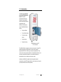
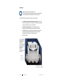
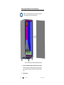
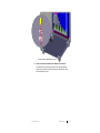
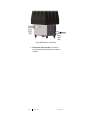
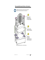
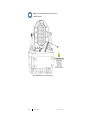
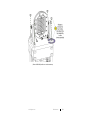
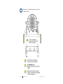
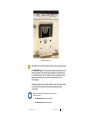
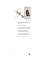
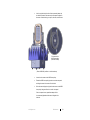
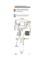
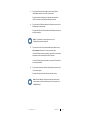
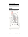
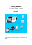
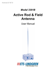
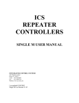
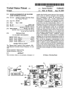
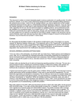
1
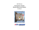
AMS-8040 Series Antenna Measurement System User Manual AMS-8040 shown with EUT; EUT not included ETS-Lindgren Inc. reserves the right to make changes to any products herein to improve functioning or design. Although the information in this document has been carefully reviewed and is believed to be reliable, ETS-Lindgren does not assume any liability arising out of the application or use of any product or circuit described herein; nor does it convey any license under its patent rights nor the rights of others. All trademarks are the property of their respective owners. © Copyright 2014–2015 by ETS-Lindgren Inc. All Rights Reserved. No part of this document may be copied by any means without written permission from ETS-Lindgren Inc. Trademarks used in this document: The ETS-Lindgren logo is a registered trademark, and FlexSorb and EMQuest are trademarks of ETS-Lindgren Inc. Revision Record MANUAL,AMS-8040 SERIES | Part #399383, Rev. B ii Revision Description Date A Initial Release June, 2014 B Added AMS-8041 product information; Added EC Declaration of Conformity April, 2015 ets-lindgren.com Table of Contents Notes, Cautions, and Warnings ................................................ v 1.0 Introduction .......................................................................... 7 Standard Configuration ............................................................................... 8 Test Chamber ..................................................................................... 8 2-Axis Positioner ................................................................................. 9 Antennas .......................................................................................... 10 Ethernet-to-Fiber Optic Converter ..................................................... 11 RF Combiner .................................................................................... 11 Required Items (Not Included) .................................................................. 12 Optional Support for Passive Antenna Measurements: AMS-8041 Only.... 12 ETS-Lindgren Product Information Bulletin ............................................... 12 2.0 Maintenance ....................................................................... 13 Flash Upgrading the Motor Base............................................................... 14 Maintenance of Fiber Optics ..................................................................... 14 Removing and Replacing the Centerpiece Panel ...................................... 15 Removing the Positioner from the Enclosure ............................................ 16 Removing and Replacing the Positioner Top Assembly ............................ 21 Reset the Motor Base to Zero: For AMS-8040 Only .................................. 26 Reset the Motor Base to Zero: For AMS-8041 Only .................................. 31 Replacement and Optional Parts .............................................................. 35 Service Procedures .................................................................................. 35 3.0 Specifications ..................................................................... 37 Electrical Specifications ............................................................................ 37 Physical Specifications ............................................................................. 38 4.0 Operation ............................................................................ 39 Electrical Requirements ............................................................................ 39 Connecting Cables to the Connector Panel............................................... 40 Attaching Handheld Device to the Centerpiece Panel ............................... 42 5.0 Positioner Command Set .................................................. 43 AXIS2 and AXIS3 ..................................................................................... 43 General Command Structure .................................................................... 44 System Commands .................................................................................. 45 ets-lindgren.com iii Identification...................................................................................... 45 Name ................................................................................................ 45 IP Address ........................................................................................ 45 Network Mask ................................................................................... 45 Trigger Commands ................................................................................... 46 Temperature Commands .......................................................................... 47 Temperature Alarm ........................................................................... 47 Temperature Read Current ............................................................... 47 Temperature Set Point ...................................................................... 47 Axis Commands........................................................................................ 48 Configure Subset .............................................................................. 48 Control Subset .................................................................................. 50 Read Subset ..................................................................................... 51 Appendix A: Warranty ............................................................. 53 Appendix B: EC Declaration of Conformity .......................... 55 iv ets-lindgren.com Notes, Cautions, and Warnings Note: Denotes helpful information intended to provide tips for better use of the product. Caution: Denotes a hazard. Failure to follow instructions could result in minor personal injury and/or property damage. Included text gives proper procedures. Warning: Denotes a hazard. Failure to follow instructions could result in SEVERE personal injury and/or property damage. Included text gives proper procedures. Note: See the ETS-Lindgren Product Information Bulletin for safety, regulatory, and other product marking information. ets-lindgren.com v This page intentionally left blank. vi ets-lindgren.com 1.0 Introduction The ETS-Lindgren AMS-8040 Series Antenna Measurement System is a compact, fully-anechoic RF enclosure designed for making wireless device over-the-air performance measurements in the 400 MHz to 6 GHz frequency range. The AMS-8040 Series is ideal for: Design verification Pre-certification testing Production sample testing Desense testing Regression testing AMS-8040 shown with EUT; EUT not included The AMS-8040 Series is designed to provide an environment for relative OTA radiation performance of wireless devices. It can be used to measure approximate EIRP, EIS, or RSSI in a given direction and polarization. These results can be used to compare the behavior of multiple identical devices, or the same device under different conditions, such as external interference or desensitization due to other platform components or radios. Additionally, the AMS-8041 is capable of performing passive antenna measurements; contact ETS-Lindgren Sales for more information on this option (must be specified at the time of initial purchase). ets-lindgren.com Introduction 7 Standard Configuration TEST CHAMBER As a self-contained, freestanding test chamber, the AMS-8040 Series is an ideal solution when space is limited. Equipped with roller casters, the unit fits through a typical 3-ft x 7-ft door (0.9 m x 2.1 m) and can be moved easily from one test group to another, making it an excellent choice for multiple research and development groups. The AMS-8040 Series is constructed with the same RF shielding and shielded door technology used in the construction of all ETS-Lindgren full certification wireless test chambers. The RF shielded door uses compressible finger stock in a knife-edge configuration, and two latch points with a single point handle provide secure sealing and one-hand operation. Typical RF isolation of both the shielding and door is greater than 80 dB. FlexSorb™, a flexible RF absorber that bends and returns to its original form, is designed to eliminate breakage from extended lab use. The absorber is performance optimized and limits reflections and moding for more accurate, repeatable measurements. Tapered wedges line the walls, pyramidal absorber is used on the floor, and lossy foam lines the antenna. A connector panel provides two SMA connectors and two Type N connectors for DUT input/output, and one BNC connector for triggered acquisition functionality. 8 Introduction ets-lindgren.com 2-AXIS POSITIONER The AMS-8040 Series includes a unique, light duty 2-axis positioner to enable 3D antenna pattern measurements. The positioner is constructed of primarily low-dielectric materials, and is designed for the following: AMS-8040 positioner: Handheld devices weighing up to 1 lb (0.45 kg). AMS-8041 positioner: Handheld devices weighing up to 2.2 lb (1.0 kg). The positioner is controlled over Ethernet by ETS-Lindgren EMQuest™ EMQ-100 Antenna Measurement Software or by customer-written software installed on a control computer. The control signal is passed from the test chamber over fiber optics, and is converted to Ethernet via an Ethernet-to-fiber optic converter (included) at the control computer. Note: Varieties of test packages are available; contact ETS-Lindgren for information. ets-lindgren.com Introduction 9 ANTENNAS Note: RF cabling for the measurement and communication antennas is included; the cables are installed inside the test chamber, from each antenna to the connector panel. These ETS-Lindgren antennas are mounted in the test chamber: (1) 3165-02 Dual-Polarized Dual-Vivaldi Array Antenna—For linear and circular measurements. The 3165-02 is mounted to the removable access panel located at the top of the enclosure. (2) Communication Antennas—Two antennas are used for communication with the equipment under test (EUT). Inside the AMS-8040 enclosure, one is mounted vertically and one is mounted horizontally; inside the AMS-8041 enclosure, both are mounted horizontally. Each antenna has a frequency range of 690 MHz to 6 GHz. In the AMS-8040 enclosure, one communication antenna is mounted vertically to one side of the positioner, and the other is mounted horizontally on the other side 10 Introduction ets-lindgren.com In the AMS-8041 enclosure, one communication antenna is mounted horizontally in front of the positioner (shown), and the other is mounted horizontally behind the positioner (not shown). In a typical usage case, the communication antennas are connected to the test instrumentation using the included RF combiner (RF cables not included). For more information, see Connecting Cables to the Connector Panel on page 40. ETHERNET-TO-FIBER OPTIC CONVERTER An Ethernet-to-fiber optic converter and a fiber optic control cable that connects the control computer to the positioner via the converter are included with the AMS-8040 Series. For other cabling, see RF and Other Cables on page 12. RF COMBINER An RF combiner is included with the AMS-8040 Series. The included RF cables are connected from the communication antennas to the connector panel. Customer-provided RF cables will connect the communication antennas to the RF combiner, and the RF combiner to the test instrumentation. For an illustration, see Connecting Cables to the Connector Panel page 40. ets-lindgren.com Introduction 11 Required Items (Not Included) Note: For ordering information, see Replacement and Optional Parts on page 31. Control computer installed with EMQuest EMQ-100 or customer-written software. ETS-Lindgren Model 3126 Series Sleeve Dipole Antenna for range calibration (a dipole antenna is included with purchase of an optional test package). RF and other cables required to perform any additional testing (additional cabling is included with purchase of an optional test package). Optional Support for Passive Antenna Measurements: AMS-8041 Only The AMS-8041 can be configured to support passive antenna measurements of handheld devices weighing up to 2.2 lb (1.0 kg); this option must be specified at the time of initial purchase of the AMS-8041. For more information, contact ETS-Lindgren Sales. ETS-Lindgren Product Information Bulletin See the ETS-Lindgren Product Information Bulletin included with your shipment for the following: 12 Warranty information Safety, regulatory, and other product marking information Steps to receive your shipment Steps to return a component for service ETS-Lindgren calibration service ETS-Lindgren contact information Introduction ets-lindgren.com 2.0 Maintenance CAUTION: Before performing any maintenance, follow the safety information in the ETS-Lindgren Product Information Bulletin included with your shipment. WARNING: Maintenance of the AMS-8040 Series is limited to components external to the test chamber, such as cables or connectors, and to the information provided in this section. WARRANTY Clean the exterior of the cabinet using a damp cloth and mild cleaner. Always unplug the unit before cleaning. CAUTION: Other than the centerpiece panel, do not touch the foam parts of the positioner. Skins oils and other debris can damage and discolor the foam. CAUTION: ONLY QUALIFIED SERVICE PERSONNEL should remove or replace the positioner from the test chamber. The positioner is a precise, delicate component, and any attempt to remove and replace it may damage it. Note: If you have any questions concerning maintenance, contact ETS-Lindgren Customer Service. ets-lindgren.com Maintenance 13 Flash Upgrading the Motor Base The fiber optic interface and motor base control boards support flash upgrades to firmware and programmable logic. As revisions become available, both the firmware and upgrade utility will be available for download from www.ets-lindgren.com/softwareupdates. It is the responsibility of the customer to periodically check the ETS-Lindgren website for revisions, and to download and install them. Maintenance of Fiber Optics Fiber optic connectors and cables can be damaged from airborne particles, humidity and moisture, oils from the human body, and debris from the connectors they plug into. Always handle connectors and cables with care, using the following guidelines. CAUTION: Before performing any maintenance, disconnect the fiber optic cables from the unit and turn off power. When disconnecting fiber optic cables, apply the included dust caps to the ends to maintain their integrity. Before connecting fiber optic cables, clean the connector tips and in-line connectors. Before attaching in-line connectors, clean them with moisture-free compressed air. Failure to perform these tasks may result in damage to the fiber optic connectors or cables. 14 Maintenance ets-lindgren.com Removing and Replacing the Centerpiece Panel Note: Only the centerpiece panel in the top assembly of the positioner can be replaced. If another component in the top assembly is damaged, the entire top assembly must be replaced. See page 31 for information on ordering a replacement top assembly. Note: It is not necessary to remove the positioner from the enclosure to remove and replace the centerpiece panel. (Shown: AMS-8040 positioner - outside enclosure) 1. Using your fingers, remove the two plastic thumbscrews that attach the centerpiece panel to the positioner. 2. Remove the centerpiece panel. 3. Attach the new centerpiece panel to the positioner by replacing the two thumbscrews removed in step 1. ets-lindgren.com Maintenance 15 Removing the Positioner from the Enclosure Note: To reinstall the positioner in the enclosure, reverse these steps, starting with step 6 and finishing at step 1. (Shown: Panel removed from back of AMS-8040 enclosure) 16 1. Remove the bolts that attach the back panel to the enclosure. Remove all but two of the bolts at the top of the panel and have a team member hold the panel in place when removing the last two bolts. 2. Remove panel. Maintenance ets-lindgren.com (Shown: Bottom of AMS-8040 enclosure) 3. Remove four bolts and washers from bottom of the enclosure. From the bottom of the enclosure remove the four bolts and washers that fit over the post at the bottom of each foot on the positioner; these hold the positioner in place. ets-lindgren.com Maintenance 17 (Shown: AMS-8040 positioner - outside enclosure) 4. 18 Disconnect power and fiber optic cables. On the inside of the enclosure disconnect the power cable and the fiber optic cables from the positioner. Maintenance ets-lindgren.com (Shown: AMS-8040 positioner removal from enclosure) 5. Remove positioner from enclosure. With help from a team member, carefully lift the positioner and remove it from the enclosure. Note: When reinstalling the positioner in the enclosure, ensure that the peg at the bottom of each foot on the positioner fits into the four holes at the bottom of the enclosure; see step 3 on page 17 or more information. ets-lindgren.com Maintenance 19 (Shown: AMS-8040 positioner - outside enclosure) 6. 20 Remove absorber from positioner. Remove the two halves of absorber from the positioner. Maintenance ets-lindgren.com Removing and Replacing the Positioner Top Assembly Note: Before replacing the top assembly, follow the steps on page 16 to remove the positioner from the enclosure. (Shown: AMS-8040 positioner - outside enclosure) ets-lindgren.com Maintenance 21 Note: Step 4 is for an AMS-8040 positioner only; skip for an AMS-8041 positioner. (Shown: AMS-8040 positioner - outside enclosure) 22 Maintenance ets-lindgren.com (Shown: AMS-8040 positioner - outside enclosure) ets-lindgren.com Maintenance 23 Note: Step 8 is for an AMS-8040 positioner only; skip for an AMS-8041 positioner. 24 Maintenance ets-lindgren.com AMS-8040 motor base Note: After replacing the top assembly you must reset the motor base to zero. For AMS-8040 instructions, see page 26. For AMS-8041 instructions, see page 31. ets-lindgren.com Maintenance 25 Reset the Motor Base to Zero: For AMS-8040 Only Note: After replacing the top assembly you must reset the motor base to zero. You will use the pulley clamp that shipped with the AMS-8040 to reset the motor base to zero. The pulley clamp is shipped attached to the outside of the motor base. Pulley clamp for AMS-8040 positioner (Shown: AMS-8040 positioner - outside enclosure) 26 Maintenance ets-lindgren.com 1. 2. Home each panel—Via EMQuest™ EMQ-100 Antenna Measurement Software or the Home command using customer-written software installed on a control computer. Home the outer panel/AXIS2, and then wait for the home process to complete. Home the centerpiece panel/AXIS3, and then wait for the home process to complete. If in place, remove the two end plates on the motor base to provide access to the lower pulleys. AMS-8040 motor base ets-lindgren.com Maintenance 27 3. Align the outer panel/AXIS2. (Shown: AMS-8040 positioner - outside enclosure) 28 Look through the hole in the side of the top assembly where the two belts are located. If the seam on the outer panel is aligned in the center of the side hole, go to step 4; otherwise, continue here. Maintenance ets-lindgren.com Secure the pulley clamp around the AXIS2 lower pulley. This will hold the pulley in place. Loosen the nut on the AXIS2 lower pulley. Remove the pulley clamp from around the AXIS2 lower pulley. Rotate the AXIS2 upper pulley by hand to move the outer panel and align the seam in the center of the side hole. When the seam is aligned, tighten the nut on the AXIS2 lower pulley, being careful not to move the outer panel. If the outer panel moves, repeat these steps until the nut is tightened and the seam is aligned in the side hole. ets-lindgren.com Maintenance 29 4. Align the centerpiece panel/AXIS3. Secure the pulley clamp around the AXIS3 lower pulley. This will hold the pulley in place. Loosen the nut on the AXIS3 lower pulley. Remove the pulley clamp from around the AXIS3 lower pulley. Rotate the AXIS3 upper pulley by hand to move the centerpiece panel and align it with the outer panel. The centerpiece panel should be parallel with the outer panel. When the centerpiece panel is parallel with the outer panel, tighten the nut on the AXIS3 lower pulley, being careful not to move the centerpiece panel. If the centerpiece panel moves, repeat these steps until the nut is tightened and the centerpiece panel is parallel with the outer panel. 30 5. Replace the two end plates on the motor base. 6. Reinstall the positioner in the enclosure. To reinstall the positioner in the enclosure reverse the steps on page 16, starting with step 6 and finishing at step 1. Maintenance ets-lindgren.com Reset the Motor Base to Zero: For AMS-8041 Only Note: After replacing the top assembly you must reset the motor base to zero. (Shown: AMS-8041 positioner - outside enclosure) ets-lindgren.com Maintenance 31 1. 2. Home each panel—Via EMQuest™ EMQ-100 Antenna Measurement Software or the Home command using customer-written software installed on a control computer. Home the outer panel/AXIS2, and then wait for the home process to complete. Home the centerpiece panel/AXIS3, and then wait for the home process to complete. Align the outer panel/AXIS2. (Shown: AMS-8041 positioner - outside enclosure) 32 Maintenance ets-lindgren.com Look through the hole in the side of the top assembly where the two belts are located. If the seam on the outer panel is aligned in the center of the side hole, go to step 3; otherwise, continue here. Six screws on the AXIS2 lower pulley (side with one belt) (Shown: AMS-8041 positioner - outside enclosure) Loosen the six screws on the AXIS2 lower pulley. Rotate the AXIS2 lower pulley by hand to move the outer panel and align the seam in the center of the side hole. When the seam is aligned, re-tighten the six screws on the AXIS2 lower pulley, being careful not to move the outer panel. If the outer panel moves, repeat these steps until the six screws are tightened and the seam is aligned in the side hole. ets-lindgren.com Maintenance 33 3. Align the centerpiece panel/AXIS3. Six screws on the AXIS3 lower pulley (side with two belts) (Shown: AMS-8041 positioner - outside enclosure) Loosen the six screws on the AXIS3 lower pulley. Rotate the AXIS3 lower pulley by hand to move the centerpiece panel and align it with the outer panel. The centerpiece panel should be parallel with the outer panel. When the centerpiece panel is parallel with the outer panel, re-tighten the six screws on the AXIS3 lower pulley, being careful not to move the centerpiece panel. If the centerpiece panel moves, repeat these steps until the six screws are tightened and the centerpiece panel is parallel with the outer panel. 34 Maintenance ets-lindgren.com 4. Reinstall the positioner in the enclosure. To reinstall the positioner in the enclosure reverse the steps on page 16, starting with step 6 and finishing at step 1. Replacement and Optional Parts Note: ETS-Lindgren may substitute a similar part or new part number with the same functionality for another part/part number. Contact ETS-Lindgren for questions about part numbers and ordering parts. Following are the part numbers for ordering replacement or optional parts for the AMS-8040 Series Antenna Measurement System. Part Description Part Number AMS-8040 AMS-8041 Centerpiece Panel 120512 119586 Top Assembly 120513 Contact ETS-Lindgren for ordering information Fiber Optic-to-Ethernet Converter 708043 RF Combiner 690142 Communication Antenna 705594 Range Calibration Fixture 120700 Service Procedures For the steps to return a system or system component to ETS-Lindgren for service, see the Product Information Bulletin included with your shipment. ets-lindgren.com Maintenance 35 This page intentionally left blank. 36 Maintenance ets-lindgren.com 3.0 Specifications Electrical Specifications Frequency Range: 400 MHz—6 GHz Path Length: AMS-8040: 1m (nominal) AMS-8041: 80 cm Connectors: (2) ST/Fiber Optic – for Ethernet-to-fiber optic converter (2) SMA - for DUT (2) Type N - for DUT (two are used for the communication antennas) (1) BNC connecter – for triggered acquisition functionality (1) IEC - for power input Filter: Dual-line 10-amp 60 Hz power line filter Power Requirements: Positioner and Filter 200–230 VAC 50/60 Hz 10A Ethernet-to-Fiber Optic Converter 100–240 VAC 50/60 Hz 0.6A ets-lindgren.com Specifications 37 Physical Specifications AMS-8040 AMS-8041 Test Chamber Dimensions (External): Width: 74.9 cm (29.49 in) 87.4 cm (34.4 in) Height: 194.3 cm (76.49 in) 201.4 cm (79.3 in) Depth: 86.4 cm (34.0 in) 101.1 cm (38.9 in) Door/Clear Opening Dimension: Weight (Nominal): 38 Specifications 48.3 cm x 48.3 cm (19 in x 19 in) 238 kg (525 lb) 261.3 kg (575.0 lb) ets-lindgren.com 4.0 Operation CAUTION: Before placing into operation, follow the safety information in the ETS-Lindgren Product Information Bulletin included with your shipment. CAUTION: Do not attempt to remove the positioner from the test chamber. The positioner is a precise, delicate component, and any attempt to remove and replace it may damage it. CAUTION: ONLY QUALIFIED SERVICE PERSONNEL should remove or replace the positioner from the test chamber. The positioner is a precise, delicate component, and any attempt to remove and replace it may damage it. Note: The test chamber is designed for use only with the 2-axis positioner. Note: For information on using EMQuest to operate the positioner, see the help file included with the EMQuest software. Electrical Requirements Provide power within five feet of the location where the AMS-8040 Series Antenna Measurement System will be located. For power specifications, see Power Requirements on page 37. ets-lindgren.com Operation 39 Connecting Cables to the Connector Panel Caution: Make sure the filter power switch located on the front connector panel is set to OFF before connecting any cables to the AMS-8040 Series. Note: For information on the proper handling of fiber optic cables and connectors, see Maintenance of Fiber Optics on page 14. 40 Operation ets-lindgren.com 1. Plug one end of the fiber optic cable into the transmit (Tx) and receive (Rx) connectors on the front connector panel. Plug the other ends of the fiber optic cable into the transmit and receive connectors on the Ethernet-to-fiber optic converter. 2. Plug one end of the Ethernet cable into the Ethernet connector on the Ethernet-to-fiber optic converter. Plug the other end of the Ethernet cable into the Ethernet connector on the control computer. Note: For information on required power source, see Electrical Requirements on page 39. 3. Plug one end of each of the communication antenna cables into the Comm Antenna connectors on the front connector panel. Use two RF cables (customer-provided) to connect the communication antennas from the connector panel to the RF combiner. Use one RF cable (customer-provided) to connect the RF combiner to the test instrumentation. 4. Plug one end of the power cable into the filter power connector on the front connector panel. Plug the other end of the power cable into the power source. Note: After all cables are properly connected, set the filter power switch located on the front connector panel to ON to power up the AMS-8040 Series. ets-lindgren.com Operation 41 Attaching Handheld Device to the Centerpiece Panel Note: To avoid damage to the positioner, remove the centerpiece panel from the positioner and the test chamber before attaching the handheld device. For the steps to remove and replace the centerpiece panel, see page 15. The centerpiece panel on the positioner holds the handheld device. Remove the centerpiece panel and attach the handheld device to the panel with the included rubber bands, and then re-attach the panel to the positioner. 42 Operation ets-lindgren.com 5.0 Positioner Command Set When used properly, the following commands enable programmers to develop powerful applications that can handle almost any condition the positioner may encounter. AXIS2 and AXIS3 The axes of the positioner are numbered AXIS2 and AXIS3 as follows: ets-lindgren.com Positioner Command Set 43 General Command Structure Most of the following commands use this general structure: [SUBSET:]AXIS<n[-m]>:COMMAND <argument_n>[,<argument_m>] Where: [ ] Indicates optional. < > Indicates required. COMMAND The backwards-compatible Model 2090 Multi-Device Controller command. When used by itself, controls the first device in a multi-axis system, and, when arguments are required, supports only a single argument. The command prefix in optional brackets [ ] Required to access a specific axis or multiple axes at a time. SUBSET The particular command grouping subset (e.g. configure, control, etc.). AXIS<n[-m]> Selects the desired axis or axes to control. A single index specifies a single axis (e.g. AXIS2 or AXIS3) with a single argument, while a range (e.g. AXIS2-3) specifies a range of axes with a corresponding range of arguments. Note that some commands only support single-axis control. 44 <argument_n> The single argument required for a single-axis command. [,<argument_m>] Represents the additional arguments required for an optional multi-axis command (e.g. SUBSET:AXIS2-3:COMMAND 2,3). Positioner Command Set ets-lindgren.com System Commands IDENTIFICATION Command Format: Response: Default IP Address: *IDN? ETS-Lindgren Inc., System Name, Module Name, HW x.xx FW x.xx 192.168.0.100 Port 1206 NAME Command Format: Query Format: Response: MODule:NAME <Module Name> MODule:NAME? Module Name IP ADDRESS Command Format: Query Format: Response: MODule:IPADdress <nnn.nnn.nnn.nnn> MODule:IPADdress? nnn.nnn.nnn.nnn NETWORK M ASK Command Format: Query Format: Response: Default Mask: ets-lindgren.com MODule:NETMask <nnn.nnn.nnn.nnn> MODule:NETMask? nnn.nnn.nnn.nnn 255.255.255.0 Positioner Command Set 45 Trigger Commands Configuration Query: Enable/Disable: TRIG? TRIG Format: TRIG <ON/OFF>Step Size, Reference Position, Pre-Trigger Delay, Trigger Pulse Length, Post-Trigger Delay, <HIGH/LOW> Where: Step Size: Reference Position: Pre-Trigger Delay: Trigger Pulse Length: Post Trigger Delay: High/Low: 46 Angular distance between trigger pulses in degrees. One of the positions where a trigger should occur (not necessarily a starting position). Time between reaching the target encoder position and producing a trigger pulse. Active period of the trigger pulse. Minimum inactive period after the trigger pulse before another trigger event can occur. Sets the polarity of the trigger signal. Positioner Command Set ets-lindgren.com Temperature Commands Note: Temperature values are in Celsius. TEMPERATURE ALARM When the circuit senses a temperature above this threshold it will soft stop the motors and set the fan to run at full speed (4500 RPM) until the system error is read. Soft stop means that the motors will decelerate until full stop; this can take up to 3 seconds depending on current acceleration settings. Command Format: Query Format: TEMPerature:ALARM <value> TEMPerature:ALARM? TEMPERATURE READ CURRENT Reads the current temperature inside the positioner. Query Format: TEMPerature:READ? TEMPERATURE SET POINT The temperature control system will keep the internal temperature at this set point value by increasing or decreasing the fan speed. Command Format: Query Format: ets-lindgren.com TEMPerature:SETPoint <value> TEMPerature:SETPoint? Positioner Command Set 47 Axis Commands CONFIGURE SUBSET Set/Query lower limit AXIS<n[-m]>:CLimit <limit_n>[,<limit_m>] AXIS<n[-m]>:LLimit <limit_n>[,<limit_m>] Set/Query upper limit AXIS<n[-m]>:ULimit <limit_n>[,<limit_m>] AXIS<n[-m]>:WLimit <limit_n>[,<limit_m>] Set/Query current position AXIS<n[-m]>:CPosition <position_n>[,< position _m>] Set/Query continuous rotation (ignore soft limits) AXIS<n[-m]>:CRotation Set non continuous mode (restrict motion between upper and lower limits) AXIS<n[-m]>:NCRotation Set/Query acceleration in seconds AXIS<n[-m]>:ACCeleration <acceleration> [s] Set/Query acceleration in milliseconds AXIS<n[-m]>:A <acceleration> [ms] 48 Positioner Command Set ets-lindgren.com Set preset speed AXIS<n[-m]>:<SS# speed>[,<SS# speed>] # A value from 1–8 to select the preset speed register to set. <speed> Value from 0–255 representing the desired speed setting for the specified speed selection. A value of 0 represents the minimum available speed of the device, and a value of 255 represents the maximum. The actual speed of the device is given approximately by the formula: Actual Speed = <speed> (MaxSpeed – MinSpeed) / 255 + MinSpeed Set query a preset speed setting for a variable speed device AXIS<n[-m]>:SS#? # A value from 1–8 to select the preset speed register to query. (Firmware revisions prior to v3.00 only support 4 speed settings.) Note: There can be no white space between the command, the number, and the question mark. Response: <speed setting> Value between 0 (minimum) and 255 (maximum) speed. Set/Query preset speed selection AXIS<n[-m]>:Speed <speed> Query if axis has been homed AXIS<n[-m]>:ZERO? ets-lindgren.com Positioner Command Set 49 CONTROL SUBSET Move axis counterclockwise AXIS<n>:CCw AXIS<n>:DN Move axis clockwise AXIS<n>:CW AXIS<n>:UP Stop motion AXIS<n[-m]>:STop Seek specified target AXIS<n[-m]>:SK<target_n>[,< target_m>] Seek specified target in negative direction AXIS<n[-m]>:SKNegative <target_n>[,< target_m>] Seek specified target in positive direction AXIS<n[-m]>:SKPositive <target_n>[,< target_m>] Seek relative to the current position AXIS<n[-m]>:SKRelative <target_n>[,< target_m>] Seek home sensor AXIS<n[-m]>:HOME Toggle Scan Mode - move axis up and down between the soft limits AXIS<n[-m]>:SCAN 50 Positioner Command Set ets-lindgren.com READ SUBSET Query current position AXIS<n[-m]>:CPosition? Response: angle Query current motion direction AXIS<n[-m]>:DIRection? Response 0 Not moving Response +1 Moving clockwise Response –1 Moving counter clockwise Query if axis has been homed AXIS<n[-m]>:HOME? Response: [0|1] ets-lindgren.com Positioner Command Set 51 This page intentionally left blank. 52 Positioner Command Set ets-lindgren.com Appendix A: Warranty Note: See the Product Information Bulletin included with your shipment for the complete ETS-Lindgren warranty for your AMS-8040 Series. DURATION OF WARRANTIES FOR AMS-8040 SERIES All product warranties, except the warranty of title, and all remedies for warranty failures are limited to the durations outlined below for each product. Product Warranted Duration of Warranty Period AMS-8040 Series Antenna Measurement System, Anechoic Performance 5 Years Filters 1 Year Doors & Accessories 1 Year Positioning Equipment 2 Years Antennas 2 Years Cables/connectors 1 Year ets-lindgren.com Warranty 53 This page intentionally left blank. 54 Warranty ets-lindgren.com Appendix B: EC Declaration of Conformity 15 EC Declaration of Conformity We, ETS-Lindgren Inc., 1301 Arrow Point Drive, Cedar Park, Texas, 78613, USA, declare under our sole responsibility that the product: Product: AMS-8040 Antenna Measurement System, AMS-8041 Antenna Measurement System Description: It is a self-contained enclosure for making wireless device over-the-air performance and passive antenna pattern measurements. to which this declaration relates in conformity with the following European, harmonized and published standards at date of this declaration: Directive(s): ☒ Low Voltage Directive (LVD): 73/23/EEC and its amending directives ☒ Electromagnetic Compatibility Directive (EMC): 89/336/EEC and its amending directives Authorized Signature: March 25, 2015 Jim Psencik Date of Issue Vice President, Engineering ETS-Lindgren Inc. ets-lindgren.com EC Declaration of Conformity 55