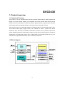
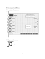
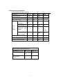
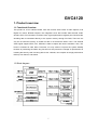
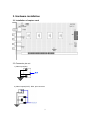
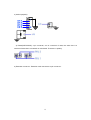
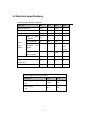
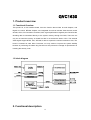
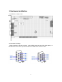
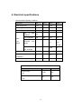
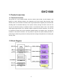
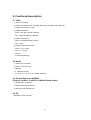
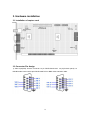
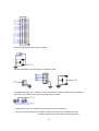
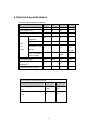
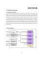
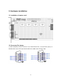
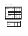
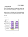
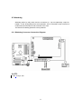
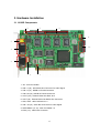
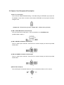
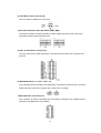
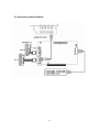
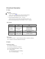
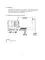
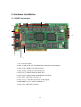
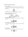
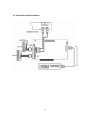
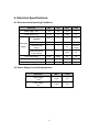
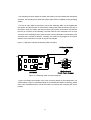
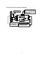
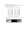
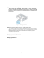
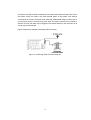
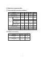
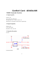
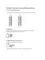
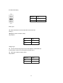
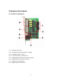
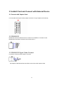
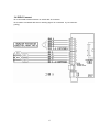
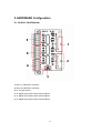
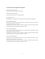
1
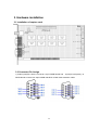
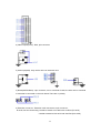
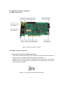
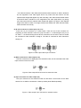
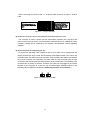
iNetDVR G(General),V(Video),C(Capture) Series Hardware Manual GVC0430 1. Product overview 1.1 Functional Overview This product is, a PCI interface board, have the function about Video & Audio Capture and Digital I/O control. BT878A Chipset, one integrated circuit that includes Video decode, audio decode, GPIO, PCI Controller is inserted, and have a great performance against price. Because the decoding data is transmitted directly to the system memory through PCI BUS. There are not only do not need the memory on board but also is not almost the load in CPU. The external Video signal support NTSC, PAL, SECAM, is able to capture the various resolutions. Also, The board is inserted he extra Micro Processor, not only assist to improve the system stability because of performing the Watch dog function but also prevent the outrage of reproduction as inserting the security code. As being able to use several boards (up to 4), can comprise as a high performance DVR up to 16 channel, 120 frames. 1.2 Block diagram 2 2. Functional description 2.1 Video 1) Video Input 4CH 2) Video input signal: NTSC, PAL(But, Not use to mix NTSC, PAL cameras) 3) Support monochrome, color 4) Capture resolution - NTSC : 640*480, 640*240, 320*240 - PAL : 768*576, 768*288, 384*288 5) Total Capture frame - NTSC : 30 fps(frames per second) - PAL : 25 fps 6) Capture frame per Channel - NTSC : 7.5-30 fps - PAL : 6.25-25 fps 7) TV-out - 1 channel(Switching) 2.2 Audio 1) Audio input 1 channel 2) Level : mono line, Mic 3) Quality - 8, 16bit/sample A/D - 4, 5.6, 8, 11.2, 16, 22.4, 32, 44.8kHz sampling 2.3 Control Extension&RS485 (Refer to ConExt2 Option board) 1) Digital Input 4 channels 2) Alarm Output 4 channels 3) RS-232 to Rs-422/485 Port 2.4 Etc 1) Watch-Dog : Drive the relay 3 3. Hardware installation 3.1 installation of capture card 3.2 The pin-out of connector 1) Video Input(VIN) 4 2) Video Output(VOUT): RCA, 2pin connector VOUT 3) Audio Input(AIN) AIN 4) Reset(WATCHDOG): 2 pin connector, one is a terminal of reset, the other One is a terminal of reset that is connected on main board. There are no polarity. PIN 2 PIN 1 5) Extension connector : Extension card connects to 20 pin connector . 5 4. Electrical specifications Recommended operating conditions Parameter Min Type Max Units Power supply +5V 4.75 5 5.25 V Power supply +12V 11 12 13 V Power supply -12V -11 -12 -13 V 0.5 1 2 V 143 286 572 mV Peak to peak amplitude Video Sync Amplitude Input Horizontal Range Range Lock % - - ±7 Line Length Color sub-carrier - - ±800 Hz Audio Input Range 0.01 2.593 3.3 VP-P Ambient operating temperature 0 65 °C Ambient operating humidity 0 90 % Lock-in Range Power supply current requirements Parameter Power supply +5V Power supply -12V Max Units 1,080 mA 55 mA 6 of GVC4120 1. Product overview 1.1 Functional Overview This product is, a PCI interface board, have the function about Video & Audio Capture, And Digital I/O control. BT878A Chipset, one integrated circuit that include Video decode, audio decode, GPIO, PCI Controller is inserted, have a great performance against price. Because the decoding data is transmitted directly to the system memory through PCI BUS, There are not only do not need the memory on board but also is not almost the load in CPU. The external Video signal support NTSC, PAL, SECAM, is able to capture the various resolution. Also, The board is inserted he extra Micro Processor, not only assist to improve the system stability because of performing the Watch dog function but also prevent the outrage of reproduction as inserting the security code. As being able to use 2 boards, can comprise as a high performance DVR up to 8 channel, 240 frames. 1.2 Block diagram 7 2. Functional description 2.1 Video 1) Video Input 4CH 2) Video input signal: NTSC, PAL(But, Not use to mix NTSC, PAL cameras) 3) Support monochrome, color 4) Capture resolution - NTSC : 640*480, 640*240, 320*240 - PAL : 768*576, 768*288, 384*288 5) Total Capture frame - NTSC : 120 fps(frames per second) - PAL : 100 fps 6) Capture frame per Channel - NTSC : 30 fps - PAL : 25 fps 7) TV-out - 1 channel(Switching) 2.2 Audio 1) Audio input 4 channels 2) Level : mono line, Mic 3) Quality - 8, 16bit/sample A/D - 4, 5.6, 8, 11.2, 16, 22.4, 32, 44.8kHz sampling 2.3 Control Extension&RS485 (Refer to ConExt1 Option board) 1) Digital Input 4 channels 2) Alarm Output 4 channels 3) RS-232 to Rs-422/485 Port 2.4 Etc. 1) Watch-Dog : Drive by Relay 8 3. Hardware installation 3.1 installation of capture card 3.2 Connector pin-out 1) Video Input(VIN) VIN 2) Video Output(VOUT): RCA, 2pin connector 9 3) Audio Input(AIN) AIN AIN AIN AIN 1 2 3 4 1 5 4) Reset(WATCHDOG): 2 pin connector, one is a terminal of reset, the other One is a terminal of reset that is connected on main board. There are no polarity. 5) Extension connector : Extension card connects to 20 pin connector . 10 4. Electrical specifications Recommended operating conditions Parameter Min Type Max Units Power supply +5V 4.75 5 5.25 V Power supply +12V 11 12 13 V Power supply -12V -11 -12 -13 V 0.5 1 2 V 143 286 572 mV Peak to peak amplitude Sync Amplitude Video Input Horizontal Range Range Lock - - ±7 Line Length Color sub-carrier Lock-in Range Audio Input Range Ambient % operating temperature Ambient operating humidity - - ±800 Hz 0.01 2.593 3.3 VP-P 0 65 °C 0 90 % Power supply current requirements Parameter Power supply +5V Power supply -12V 11 Max Units 1,080 mA 55 mA of GVC1630 1. Product overview 1.1 Functional Overview This product is, a PCI interface board, have the function about Video & Audio Capture, and Digital I/O control. BT878A Chipset, one integrated circuit that includes Video decode, audio decode, GPIO, PCI Controller is inserted, have a great performance against price. Because the decoding data is transmitted directly to the system memory through PCI BUS, There are not only do not need the memory on board but also is not almost the load in CPU. The external Video signal support NTSC, PAL, SECAM, is able to capture the various resolutions. Also, The board is inserted he extra Micro Processor, not only assist to improve the system stability because of performing the Watch dog function but also prevent the outrage of reproduction as inserting the security code. 1.2 block diagram 2. Functional description 12 2.1 Video 1) Video Input 16CH 2) Video input signal: NTSC, PAL(But, Not use to mix NTSC, PAL cameras) 3) Support monochrome, color 4) Capture resolution - NTSC : 640*480, 640*240, 320*240 - PAL : 768*576, 768*288, 384*288 5) Total Capture frame - NTSC : 30 fps(frames per second) - PAL : 25 fps 6) Capture frame per Channel - NTSC : 1.8 - 30 fps - PAL : 1.5 - 25 fps 7) TV-out - 1 channel(Switching) 2.2 Audio 1) Audio input 1 channel 2) Level : mono line, Mic 3) Quality - 8, 16bit/sample A/D - 4, 5.6, 8, 11.2, 16, 22.4, 32, 44.8kHz sampling 2.3 Control Extension & RS485 (Refer to ConExt1 , ConExt3, ConExt4 Option board) 1) Digital Input 16 channels 2) Alarm Output 4(16) channels 3) RS-232 to Rs-422/485 Port 2.4 Etc 1) Watch-Dog : Drive the relay 13 3. Hardware installation 3.1 installation of capture card 3.2 Connector Pin Assign 1) Video Input(VIN): Use the connector 15 pin DSUB female and 40 pin(for back panel). 15 DSUB female connect with 15pin DSUB male RCA or BNC Video extension cable. 14 2) Video Output(VOUT): RCA, 2pin connector 3) Audio Input(AIN): Only use the AIN 4 of extension card. 4) Reset(WATCHDOG): 2 pin connector, one is a terminal of reset, the other one is a terminal of reset that is connected on the main board. There are no polarity. 5) Extension connector : Extension card connects to 20 pin connector . DI 4CH, DO 4CH Connecting / enable to extend to DI 16CH with ConExt3 (DI 12CH) / enable to extend to DO 16CH with ConExt4 (DO 12CH) 15 4. Electrical specifications Recommended operating conditions Parameter Min Type Max Units Power supply +5V 4.75 5 5.25 V Power supply +12V 11 12 13 V Power supply -12V -11 -12 -13 V 0.5 1 2 V 143 286 572 mV Peak to peak amplitude Sync Amplitude Video Input Horizontal Range Range Lock - - ±7 Line Length Color sub-carrier Lock-in Range Audio Input Range Ambient % operating temperature Ambient operating humidity - - ±800 Hz 0.01 2.593 3.3 VP-P 0 65 °C 0 90 % Power supply current requirements Parameter Power supply +5V Power supply -12V 16 Max Units 1,080 mA 55 mA of GVC1660 1. Product overview 1.1 Functional Overview This product is, a PCI interface board, have the function about Video & Audio Capture, and Digital I/O control. BT878A Chipset, one integrated circuit that include Video decode, audio decode, GPIO, PCI Controller is inserted, have a great performance against price. Because the decoding data is transmitted directly to the system memory through PCI BUS, There are not only do not need the memory on board but also is not almost the load in CPU. The external Video signal support NTSC, PAL, SECAM, is able to capture the various resolution. You can use to combine the overlay card, so be composite a 480fps overlay, a 60 capture. Also, The board is inserted he extra Micro Processor, not only assist to improve the system stability because of performing the Watch dog function but also prevent the outrage of reproduction as inserting the security code. 1.2 Block Diagram 17 2. Functional description 2.1 Video 1) Video Input 16CH 2) Video input signal: NTSC, PAL(But, Not use to mix NTSC, PAL cameras) 3) Support monochrome, color 4) Capture resolution - NTSC : 640*480, 640*240, 320*240 - PAL : 768*576, 768*288, 384*288 5) Total Capture frame - NTSC : 60 fps(frames per second) - PAL : 50 fps 6) Capture frame per Channel - NTSC : 3.75 - 30 fps - PAL : 3.1 - 25 fps 7) TV-out - 1 channel(Switching) 2.2 Audio 1) Audio input 2 channel 2) Level : mono line, Mic 3) Quality - 8, 16bit/sample A/D - 4, 5.6, 8, 11.2, 16, 22.4, 32, 44.8kHz sampling 2.3 Control Extension & RS485 (Refer to ConExt1, ConExt3, ConExt4 Option board) 1) Digital Input 16 channel 2) Alarm Output 4(16) channel 3) RS-232 to Rs-422/485 Port 2.4 Etc - Watchdog : Drive the relay 18 3. Hardware installation 3.1 Installation of capture card 3.2 Connector Pin Assign 1) Video Input(VIN): Use the connector 15 pin DSUB female and 40 pin(for back panel). 15 DSUB female connect with 15pin DSUB male RCA or BNC video extension cable. 19 2) Video Output(VOUT): RCA, 2pin connector 3) Audio Input(AIN): Only use the AIN 4 of extension card. 4) Reset(Watch-Dog): 2 pin connector, one is a terminal of reset, the other one is a terminal of reset that is connected on the main board. There are no polarity. 5) Extension connector : Extension card connects to 20 pin connector . DI 4CH, DO 4CH Connecting / enable to extend to DI 16CH with ConExt3 (DI 12CH) / enable to extend to DO 16CH with ConExt4 (DO12CH) 20 4. Electrical specifications Recommended operating conditions Parameter Min Type Max Units Power supply +5V 4.75 5 5.25 V Power supply +12V 11 12 13 V Power supply -12V -11 -12 -13 V 0.5 1 2 V 143 286 572 mV Peak to peak amplitude Video Sync Amplitude Input Horizontal Range Range Lock - - ±7 Lock-in Range Audio Input Range operating temperature Ambient operating humidity - - ±800 Hz 0.01 2.593 3.3 VP-P 0 65 °C 0 90 % Power supply current requirements Parameter Power supply +5V Power supply -12V Line Length Color sub-carrier Ambient % Max Units 1,080 mA 55 mA 21 of GVC16120 1. Product overview 1.1 Functional Overview This product is, a PCI interface board, have the function about Video & Audio Capture, and Digital I/O control. BT878A Chipset, one integrated circuit that include Video decode, audio decode, GPIO, PCI Controller is inserted, have a great performance against price. Because the decoding data is transmitted directly to the system memory through PCI BUS, There are not only do not need the memory on board but also is not almost the load in CPU. The external Video signal support NTSC, PAL, SECAM, is able to capture the various resolution. You can use to combine the overlay card, so be composite a 480fps overlay, a 120 capture. Also, The board is inserted he extra Micro Processor, not only assist to improve the system stability because of performing the Watch dog function but also prevent the outrage of reproduction as inserting the security code. 1.2 Block Diagram 22 2. Functional description 2.1 Video 1) Video Input 16CH 2) Video input signal: NTSC, PAL(But, Not use to mix NTSC, PAL cameras) 3) Support monochrome, color 4) Capture resolution - NTSC : 640*480, 640*240, 320*240 - PAL : 768*576, 768*288, 384*288 5) Total Capture frame - NTSC : 120 fps(frames per second) - PAL : 100 fps 6) Capture frame per Channel - NTSC : 7.5 - 30 fps - PAL : 6.25 - 25 fps 7) TV-out - 1 channel(Switching) 2.2 Audio 1) Audio input 4 channel 2) Level : mono line, Mic 3) Quality - 8, 16bit/sample A/D - 4, 5.6, 8, 11.2, 16, 22.4, 32, 44.8kHz sampling 2.3 Control Extension , RS485 (Refer to ConExt1 ,ConExt3 ,ConExt4 Option board) 1) Digital Input 16 channel 2) Alarm Output 4(16) channel 3) RS-232 to Rs-422/485 Port 2.4 Etc - Watchdog : Drive the relay 23 3. Hardware installation 3.1 Installation of capture card 3.2 Connector Pin Assign 1) Video Input(VIN): Use the connector 15 pin DSUB female and 40 pin(for back panel). 15 DSUB female connect with 15pin DSUB male RCA or BNC video extension cable. 24 2) Video Output(VOUT): RCA, 2pin connector 3) Audio Input(AIN): Only use the AIN 4 of extension card. 4) Reset(WATCHDOG): 2 pin connector, one is a terminal of reset, the other one is a terminal of reset that is connected on the main board. There are no polarity. 5) Extension connector : Extension card connects to 20 pin connector . DI 4CH, DO 4CH Connecting / enable to extend to DI 16CH with ConExt3 (DI 12CH) / enable to extend to DO 16CH with ConExt4 (DO 12CH) 25 4. Electrical specifications Recommended operating conditions Parameter Min Type Max Units Power supply +5V 4.75 5 5.25 V Power supply +12V 11 12 13 V Power supply -12V -11 -12 -13 V 0.5 1 2 V 143 286 572 mV Peak to peak amplitude Sync Amplitude Video Input Horizontal Range Range Lock - - ±7 Line Length Color sub-carrier Lock-in Range Audio Input Range Ambient % operating temperature Ambient operating humidity - - ±800 Hz 0.01 2.593 3.3 VP-P 0 65 °C 0 90 % Power supply current requirements Parameter Power supply +5V Power supply -12V 26 Max Units 1,080 mA 55 mA of GVC16240 1. Product overview 1.1 Functional Overview This product is, a PCI interface board, have the function about Video & Audio Capture, and Digital I/O control. BT878A Chipset, one integrated circuit that include Video decode, audio decode, GPIO, PCI Controller is inserted, have a great performance against price. Because the decoding data is transmitted directly to the system memory through PCI BUS, There are not only do not need the memory on board but also is not almost the load in CPU. The external Video signal support NTSC, PAL, SECAM, is able to capture the various resolution. You can use to combine the overlay card, so be composite a 480fps overlay, a 240 capture. Also, The board is inserted he extra Micro Processor, not only assist to improve the system stability because of performing the Watch dog function but also prevent the outrage of reproduction as inserting the security code. 1.2 Block Diagram 27 2. Functional description 2.1 Video 1) Video Input 16CH 2) Video input signal: NTSC, PAL(But, Not use to mix NTSC, PAL cameras) 3) Support monochrome, color 4) Capture resolution - NTSC : 640*480, 640*240, 320*240 - PAL : 768*576, 768*288, 384*288 5) Total Capture frame - NTSC : 240 fps(frames per second) - PAL : 200 fps 6) Capture frame per Channel - NTSC : 15 - 30 fps - PAL : 12.5 - 25 fps 7) TV-out - 1 channel(Switching) 2.2 Audio 1) Audio input 8 channel 2) Level : mono line, Mic 3) Quality - 8, 16bit/sample A/D - 4, 5.6, 8, 11.2, 16, 22.4, 32, 44.8kHz sampling 2.3 Control Extension & RS485 (Refer to ConExt1, ConExt3, ConExt4 Option board) 1) Digital Input 16 channel 2) Alarm Output 4(16) channel 3) RS-232 to Rs-422/485 Port 2.4 Etc - Watch-Dog : Drive the relay 28 3. Hardware installation 3.1 Installation of capture card 3.2 Connector Pin Assign 1) Video Input(VIN): Use the connector 15 pin DSUB female and 40 pin(for back panel). 15 DSUB female connect with 15pin DSUB male RCA or BNC video extension cable. 29 2) Video Output(VOUT): RCA, 2pin connector 3) Audio Input(AIN): Only use the AIN 4 of extension card. 4) Reset(WATCHDOG): 2 pin connector, one is a terminal of reset, the other one is a terminal of reset that is connected on the main board. There are no polarity. 5) Extension connector : Extension card connects to 20 pin connector . DI 4CH, DO 4CH Connecting / enable to extend to DI 16CH with ConExt3 (DI 12CH) / enable to extend to DO 16CH with ConExt4 (DO 12CH) 30 4. Electrical specifications Recommended operating conditions Parameter Min Type Max Units Power supply +5V 4.75 5 5.25 V Power supply +12V 11 12 13 V Power supply -12V -11 -12 -13 V 0.5 1 2 V 143 286 572 mV Peak to peak amplitude Video Sync Amplitude Input Horizontal Range Range Color Lock % - - ±7 Line Length sub-carrier - - ±800 Hz Audio Input Range 0.01 2.593 3.3 VP-P Ambient operating temperature 0 65 °C Ambient operating humidity 0 90 % Lock-in Range Power supply current requirements Parameter Power supply +5V Power supply -12V 31 Max Units 1,080 mA 55 mA of GVC16120R 1. Product Overview 1.1 Overview 16120R is a video capture card for PC based DVR and supports audio capture, real-time display, digital input, digital output, and watchdog function as well as video capture. Video/audio data which is input through 16120R is uncompressed raw data of which compression and recording should be done by software on PC. 1.2 Block Diagram 32 2. Functional Description 2.1 Video - Video Input Number of Channel: 16 Input : Color Camera (NTSC, PAL), Black and White Camera ( Connections : 15pin DSUB Cable 2EA, 40pin connector ( Recommended Signal Range: 0.25V ~ 1.4V (p-p) (AGC function may not work when the signal range is above 1.4V.) ( Recommended Signal Range for Video Capture: 0.125V ~ 2.5V(p-p) - Video Capture Classification Capture Resolution NTSC PAL 720*480, 720*240, 704*480, 704*240, 640*480, 640*240, 320*240, 352*240, 320*240 Capture Rate Capture Rate per Channel 720*576, 720*288, 704*576, 704*288, 640*480, 640*240, 360*288, 352*288, 320*240 Max 120 FPS Max 100 FPS 7 FPS ~ 8 FPS 6 FPS ~ 7 FPS - Video Output Number of channel : 1 (channel selection possible, controlled by software) Connection : RCA Jack or Molex 2Pin Connector 2.2 Audio - Audio Input, Capture Number of Channel : 4 Input Type : Microphone, Line(mono) Recommended Signal Range : 1V(p-p) Sampling Quality ► 8, 16bit/sample (A/D Convert Sampling) ► 4, 8, 16, 32 kHz Sampling 33 2.3 Watchdog Watchdog works by relay switch and two connectors (J1, J2) are respectively a 2pin PinHeader. J1 and J2 physically do the same operation; one is connected to reset connector of mother board and the other to reset connector of the case. The interval of watchdog operation is set by software. 2.3.1 Watchdog Connector Connection Diagram 2.4 ETC - PCB : 8-Layer, PCI 34 3. Hardware Installation 3.1 16120R Components 6 7 8 9 5 10 4 3 2 1 1. JP1 : 2Pin Pin-Header 2. AIN 1-4 (J5) : 5Pin Molex Box Connector for Audio Signal 3. VIN 1-8 (J7) : DSUB-15 Female Connector 4. VIN 9-16 (J8) : DSUB-15 Female Connector 5. VOUT (J10) : External Video Out RCA Jack 6. VOUT (J9) : External Video Out Molex 2Pin Connector 7. SW1, SW2 : 16Pin DIP Switch x 2 8. VIN 1-16 (J6) : 40Pin Box Connector for Video Signal 9. WATCHDOG (J1, J2) : 2Pin Pin-Header x 2 10. DIO (J11) : 20Pin Box Connector 35 3.2 Capture Card Component Description 1) 2Pin Pin-Header(JP1) This is used to enable EEPROM writing. To do data writing on EEPROM, put jumper into Pin-Header. If user does not need to write data on EEPROM, set the jumper off before using the card. (Jumper ON : EPROM Writing Enable, Jumper OFF : EPROM Writing Disable) 2) AIN 1-4 5Pin Molex Box Connector(J5) This is a connector for audio input 1-4 and connected to J5 of AudExt2 Card. (AudExt2 Card is option.) 3) VIN 1-8 DSUB-15 Female Connector(J7) This is a video input connector. Connect this to camera output port with the provided DSUB cable. 4) VIN 9-16 DSUB-15 Female Connector(J8) This is a video input connector. Connect this to camera output port with the provided DSUB cable. 5)VOUT RCA Jack(J10) This is a RCA jack for external video out. This is connected to Video In of TV monitor. 36 6) VOUT Molex 2Pin Connector(J9) This is a video out Molex 2Pin Connector. 7)Termination Resistor 16Pin DIP Switch (SW1, SW2) This switch is used to choose termination resistor. Please set switch ‘ON’ to set to the termination resistor before using the card. 8) VIN 1-16 40Pin Box Connector(J6) This is a connector for video signal input. To prevent misconnection, the connector was grooved. 9) WATCHDOG 2Pin Pin-Header x 2(J1, J2) Two watchdog 2pin Pin-Headers are respectively connected to reset connector of mother board and reset connector of system case. The pin has no polarity. 10)DIO 20Pin Box Connector(J11) This connector is used to test DI/DO and connected to extension card. (Please refer to Extension Card Manual for more details.) 37 3.3 Connection with Peripheral 38 4. Electrical Specifications 4.1 Recommended Operating Conditions Parameter Min Typ Max Units Power supply +3.3V 3.15 3.3 3.45 V Power supply +5V 4.75 5 5.25 V Peak to peak amplitude 0.25 1 2 V Sync Amplitude 72 286 572 mV Horizontal Lock Range - - ±7 % of Line Length Color sub-carrier Lock-in Range - - ±800 Hz Audio Input Range 0.01 2.593 3.3 VP-P Ambient Operating Temperature 0 65 °C Ambient Operating Humidity 0 90 % Video Input Range 4.2 Power Supply Current Requirements Parameter Power supply +3.3V Power supply +5V 39 Max Units 1,755 mA 902 mA 5. 16120R Installation Guide 5.1. Components - 16120R Card - 2PIN Cable (for watchdog) 5.2. Option Components - AudExt2 Card - ConExt1 Card - ConExt3 Card - ConExt4 Card - PTZExt2 Card ※ Option Components are optional. User can select DI/DO extension cards among the above. Cables are provided with selected DI/DO ext cards. 5.3. Hardware Installation (1) As the below, connect 16120R Card to AudExt2 and ConExt.1616 <AudExt2 and ConExt1616 Connected to 16120R> 40 (2) Insert 16120R card vertically into PCI slot from one side to the other and then insert AudExt2 and ConExt1616 in the same way. Check if the cards were well inserted into PCI slot. <16120R, AudExt2 and ConExt1616 Inserted into PCI Slot> (3) Connect a pin of watchdog 2pin connector of 16120R to the reset switch of mother board by 2pin cable. And then connect the other pin of watchdog 2pin connector to the reset cable of PC case. Hardware installation of 16120R card finished. <Watchdog Pin Connected to Reset Pin of Mother Board> 41 5.4. Cable Connection (1) DSUB 15pin Cable DSUB 15pin Cable is used for video input (J7, J8) of 16120R Card. Connect it as the below picture. VIN1~VIN8 Terminal(J7) -Video In 1~8 Channel VIN9~VIN16 Terminal(J8) -Video In 9~16 Channel (2) External Monitor Output Terminal (J10) External monitor output port (RCA jack) is connected to external monitor. Note The video input port of DSUB 15pin is BNC type. To use RCA type, use a BNC to RCA Converter. 42 GVC16240R 1. Product Overview 1.1 Overview 16240R is a video capture card for PC based DVR and supports audio capture, real-time display, digital input, digital output, and watchdog function as well as video capture. Video/audio data which is input through 16240R is uncompressed raw data of which compression and recording should be done by software on PC. 1.2 Block Diagram 43 2.Functional Description 2.1 Video - Video Input Number of Channel: 16 Input : Color Camera (NTSC, PAL), Black and White Camera ( Connections : 15pin DSUB Cable 2EA, 40pin connector ( Recommended Signal Range: 0.25V ~ 1.4V (p-p) (AGC function may not work when the signal range is above 1.4V.) ( Recommended Signal Range for Video Capture: 0.125V ~ 2.5V(p-p) - Video Capture Classification NTSC PAL Resolution 640*480, 640*240, 320*240 768*576, 768*288, 720*576, 720*288, 640*480, 640*240, 384*288, 360*288, 320*240 Capture Rate Max 240 FPS Max 200 FPS 15 FPS ~ 30 FPS 12.5 FPS ~ 25 FPS Capture Capture Rate per Channel - Video Output Number of channel : 1 (channel selection possible, controlled by software) Connection : RCA Jack or Molex 2Pin Connector 2.2 Audio - Audio Input, Capture Number of Channel : 8 Input Type : Microphone, Line(mono) Recommended Signal Range : 1V(p-p) Sampling Quality ► 8, 16bit/sample (A/D Convert Sampling) ► 4, 8, 16, 32 kHz Sampling 44 2.3 Watchdog Watchdog works by relay switch and two connectors (J1, J2) are respectively a 2pin PinHeader. J1 and J2 physically do the same operation; one is connected to reset connector of mother board and the other to reset connector of the case. Or the vice versa. The interval of watchdog operation is set by software. 2.3.1 Watchdog Connector Connection Diagram 2.4 ETC - PCB : 10-Layer, PCI 45 3. Hardware Installation 3.1 16240R Components 8 7 6 9 5 10 4 3 1 2 1. JP1 : 2Pin Pin-Header 2. AIN 1-4, AIN 5-8 (J5, J6) : 5Pin Molex Box Connector for Audio Signal 3. VIN 1-8 (J8) : DSUB-15 Female Connector 4. VIN 9-16 (J9) : DSUB-15 Female Connector 5. VOUT (J11) : External Video Out RCA Jack 6. VOUT (J10) : External Video Out Molex 2Pin Connector 7. SW1, SW2 : 10Pin Box Connector x 2 8. VIN 1-16 (J7) : 40Pin Box Connector x Video Signal 9. WATCHDOG (J1, J2) : 2Pin Pin-Header x 2 10. DIO (J12) : 20Pin Box Connector 46 3.2 Capture Card Component Description 1) 2Pin Pin-Header(JP1) This is used to enable EEPROM writing. To do data writing on EEPROM, put jumper into Pin-Header. If user does not need to write data on EEPROM, set the jumper off before using the card. (Jumper ON : EPROM Writing Enable, Jumper OFF : EPROM Writing Disable) 2) AIN 1-4, AIN 5-8 5Pin Molex Box Connector(J5, J6) This is a connector for audio input 1-8. 3) VIN 1-8 DSUB-15 Female Connector(J8) This is a video input connector. Connect this to camera output port with the provided DSUB cable. 4) VIN 9-16 DSUB-15 Female Connector(J9) This is a video input connector. Connect this to camera output port with the provided DSUB cable. 5) VOUT RCA Jack(J11) This is a RCA jack for external video out. This is connected to Video In of TV monitor. 47 6) VOUT Molex 2Pin Connector(J10) This is a video out Molex 2Pin Connector. 7) Termination Resistor 16Pin DIP Switch (SW1, SW2) This switch is used to choose termination resistor. Please set switch ‘ON’ to set to the termination resistor. 8) VIN 1-16 40Pin Box Connector(J7) This is a connector for video signal input. To prevent misconnection, the connector was grooved. 9) WATCHDOG 2Pin Pin-Header x 2(J1, J2) Two watchdog 2pin Pin-Headers are respectively connected to reset connector of mother board and reset connector of system case. The pin has no polarity. 10) DIO 20Pin Box Connector(J12) This connector is used to test DI/DO and connected to extension card. (Please refer to Extension Card Manual for more details.) 48 3.3 Connection with Peripheral 49 4. Electrical Specifications 4.1 Recommended Operating Conditions Parameter Min Typ Max Units Power supply +3.3V 3.15 3.3 3.45 V Power supply +5V 4.75 5 5.25 V Peak to peak amplitude 0.25 1 2 V Sync Amplitude 72 286 572 mV Horizontal Lock Range - - ±7 % of Line Length Color sub-carrier Lock-in Range - - ±800 Hz Audio Input Range 0.01 2.593 3.3 VP-P Ambient Operating Temperature 0 65 °C Ambient Operating Humidity 0 90 % Video Input Range 4.2 Power Supply Current Requirements Parameter Power supply +3.3V Power supply +5V 50 Max Units 2,208 mA 1,352 mA 5. 16240R Installation Guide 5.1. Components - 16240R Card - 2PIN Cable (for watchdog) 5.2. Option Components - AudExt2(3) Card - ConExt1 Card - ConExt3 Card - ConExt4 Card - PTZExt2 Card ※ Option Components are optional. User can select DI/DO extension cards among the above. Cables are provided with selected DI/DO ext cards. 5.3. Hardware Installation (1) As the below, connect 16240R Card to AudExt3 and ConExt1616. <AudExt3 and ConExt1616 Connected to 16240R> 51 (2) Insert 16240R card vertically into PCI slot from one side to the other and then insert AudExt3 and ConExt1616 in the same way. Check if the cards were well inserted into PCI slot. <16240R, AudExt3 and ConExt1616 Inserted into PCI Slot> (3) Connect a pin of watchdog 2pin connector of 16240R to the reset switch of mother board by 2pin cable. And then connect the other pin of watchdog 2pin connector to the reset cable of PC case. Hardware installation of 16240R card finished. <Watchdog Pin Connected to Reset Pin of Mother Board> 52 5.4. Cable Connection (1) DSUB 15pin Cable DSUB 15pin Cable is used for video input (J8, J9) of 16240R Card. Connect it as the below picture. VIN1~VIN8 Terminal(J8) -Video In 1~8 Channel VIN9~VIN16 Terminal(J9) -Video In 9~16 Channel (2) External Monitor Output Terminal (J11) External monitor output port (RCA jack) is connected to external monitor. Note The video input port of DSUB 15pin is BNC type. To use RCA type, use a BNC to RCA Converter. 53 GVC16480R 1. Product overview 1.1 Functional Overview This product is, a PCI interface board, have the function about Video Capture, and Digital I/O control. The external Video signal support NTSC, PAL, SECAM, is able to capture the various resolution. Also, The board is inserted he extra Micro Processor, not only assist to improve the system stability because of performing the Watch dog function but also prevent the outrage of reproduction as inserting the security code. 1.2 Functional description ► Video capture : 16 channels at 400/480 frames/sec. ► Audio capture : 16 channels ► 16 channels of real-time display (supporting various dividing modes) ► Video Resolution : Max. 720x576 (PAL) / 720x480 (NTSC) ► Watchdog function ► Sensor/Alarm (max. 16 channel sensor, 16 channel alarm) ► External monitor display (supporting various dividing modes) ► External monitor OSD (On Screen Display) function ► Windows 2000/XP support 54 1.3 Functions of major connectors 1.3.1 Major connectors Figure 1. Major Connectors of 16480R 1.3.2 Details of major connectors (1) 3-pin jumper for restoring FPGA firmware (JP1) This is a 3 pin-header with the jumper and is used when restoring broken FPGA firmware. The jumper wire is connected to NO/UP upon delivery from the factory. Note! The jumper connector should be connected to either NO/UP or RE pin; otherwise the 16480R card cannot be recognized in the SYSTEM. Any one of the NO/UP or RE pins must be connected with the jumper. Figure 2. 3-pin jumper for restoring FPGA firmware 55 NO/UP (Normal/Update): position of the jumper at normal operation RE (Restore): position of the jumper when restoring broken FPGA firmware Care should be taken when executing work related with the FPGA firmware. The ‘FPGA firmware update method’ must be read before starting the work. (2) 5-pin connector for Audio input (J1 ~ J4) Four audio channels are connected to one set of 5pin Molex connectors. The 16480R is equipped with 4 connectors so that it can be connected with 16 audio channels. Figure 3. 5-pin connector for Audio input (3) DIP switch (75 Ω video terminal resistor - SW1, SW2) These switches turn on and off the 75Ω resistor at the terminal of the video input. SW1 controls the video inputs from 1 to 8 and SW2 controls the video inputs from 9 to 16. At the time of delivery from the factory, all of the switches in SW1 and SW2 are set in the on position. Normally, it is recommended that equipment be used in the on state as was set up in the factory. The switches are turned off in some particular cases, as described below. Figure 4. DIP switch (75 Ω video terminal resistor) ※ Cases when the video terminal resistor switches are to be turned off Several types of equipments generate, send or receive video signals and therefore require video terminal resistor of 75Ω, such as the camera and the TV monitor and the capture card. The video terminal resistor 16 pin DIP switch will serve this function in these cases. In most instances, one video output device is connected with one video input. However, sometimes, even a capture card is also to be connected to a camera in addition to the AV monitor. In case a video distributor is used, there will be no need to be concerned about the video terminal resistor, but occasionally it is impossible to use the video distributor. In this case, set the video terminal resistor switch of the capture card to off. 56 In the above instance, if the video terminal resistor switch remains on while it should be off, the magnitude of the video signal will be very weak more than normal. and the captured video images will appear very dark. Normally, if the video terminal resistor switch is turned off when it should be on, the magnitude of the video signal will be very strong more than normal and the captured video images will appear very bright. If the captured image looks either too dark or too bright, firstly check whether the video terminal resistor switch has been set correctly. (4) D-sub connector for video input (J10, J11) D-sub has 15 pin connector for 8 video inputs. There are two D-sub connector for supporting 16 video channels. Lower one (J10) is for video 1 ~ 8 channel upper one (J11) is for video 9 ~ 16 channel.Among the two D-Sub connectors, the one near to the PCI slot will be connected to video channels 1 through 8. The other is connected to video channels 9 through 16. Figure 5. D-Sub 15pin video input connectors (5) RCA connector for video output (J12) This RCA connector is for displaying on the external monitor, and is connected to the video input connector of the TV monitor. Figure 6. Video output RCA connector for external monitor (6) 2-pin connector for video output (J8) The 2-pin connector for the external monitor has the same circuit function as the RCA terminal J12. It shall be connected to a video input back panel offered separately. Figure 7. Video output 2-pin connector for external monitor 57 NOTE Only one from among the two video output terminals of J12 and J8 are to be connected to the external monitor. Be sure not to connect both of them to the external monitor simultaneously. (7) 40-pin box connector for video input (J7) This is a 40pin box connector for video signal. Functionally, it works the same way as the DSub connectors J10 and J11, but it is operated differently. ① When using as the video input : The camera shall be connected to the back panel of the video input. The video input back panel and capture card shall be connected by 40-pin flat cable. The analog signal of the camera will be put into the capture through the video input back panel and the 40-pin flat cable. Caution! At this time, be careful not to connect the camera to the D-sub connectors J10 or J11. ② When transferring a video signal to another card (ex.: OVR3500): Connect the camera to the D-Sub cable and plug this cable into the D-sub connector J10 or J11. The 40-pin box connector of the OVR3500 card and the 40-pin box connector of the 16480R shall be connected by a 40-pin flat cable. The analog signal of the camera will be put into the capture card through the D-sub connector J10 or J11 and then transferred as the video input to the OVR3500 through the 40-pin flat cable. Be sure to connect the cable correctly using a connector with a protrusion. Figure 8. Video input 40pin box connector 58 When connecting with another card, 1:1 40-pin flat cable as shown in Figure 7 shall be used. 40Pin Flat Cable to be Connected to Back Panel for Video Input or Other Cards such as OVR3500 40Pin Connector to be Connected to ECPR480 Card Figure 9. 1:1 40-pin flat cable (8) 20-pin box connector (J9) for connecting the sensor/alarm extension card This connector is used to connect with the sensor/alarm extension card. The 20-pin flat cable is used for the connection. The sensor/alarm extension card is not supplied as a basic accessory. Details will be explained in the extension card hardware manual separately supplied. (9) 2-pin connector for watchdog (J5, J6) To connect the watchdog cable, requires 2 sets of 2-pin cable. One is supplied with the capture card and the other is used with the existing reset cable enclosed in the case of the SYSTEM. Firstly, the cable in the reset connector of the SYSTEM case shall be connected to the J5 2-pin connector of the watchdog. The other cable is to be connected to the J6 2-pin connector of the watchdog and the reset connector of the motherboard. The watchdog 2-pin connector has no polarity or direction. Therefore, the cable may be plugged in the reverse direction or the connection of J5 and J6 may be interchanged. Detailed functions of the watchdog will be explained in Chapter 2.4 “Watchdog functions and connection.” J5 J6 Figure 10. Watchdog pin header 59 2. Equipment Functions 2.1 Video - Video input ► Channels : 16 ► Input : color camera (NTSC, PAL), black & white camera ► Connection : 2 sets of D-sub cable or 40-pin flat cable (for Connecting with video input back panel) ► Recommended signal range : 0.5V ~ 2V (p-p) 2.2 Audio - Audio input ► Channels : 16 ► Input type : Microphone, line in (mono) ► Recommended signal range : 0.01V ~ 3.3V (p-p) - Audio sampling quality ► Bit number per sample : 8 bit or 16 bit ► Sampling frequency : 4 KHz, 8 KHz, 16 KHz, 32 kHz 2.3 Display on external monitor ► Channels : 1 channel (supporting various dividing modes) ► Connection : RCA connector or 2-pin Molex terminal 2.4 Watchdog function and connection The watchdog is composed of the SYSTEM resetting section and buzzer. The process of resetting the system by the watchdog is similar to pressing the reset button of the system by the system user. The watchdog buzzer sounds to give a notice before rebooting the system. It can be set by UDA5API that the duration of sound and the preparation period before rebooting. (refer to “Cap5SetWathdog” at page 60 of UDA5 Cap5 API Reference-Eng.pdf). The factory default of watchdog is to disable the watchdog function and sound. Therefore, it is required to set the watchdog function and the time of sounding the buzzer before using it. The watchdog function needs to be reset every time, when the system starts or rebooted the system by the watchdog. Because it makes the watchdog’s setup becomes the factory default. 60 The watchdog cannot recognize the system was reset by the user pressing the reset button. Therefore, the watchdog may restart the system again before completely booting operating system. Two sets of 2-pin cable are required to connect the watchdog cable. One is supplied with the capture card and the other is used with the existing reset cable enclosed in the case of the system. Firstly, the cable in the reset connector of the system case shall be connected to the J5 2-pin connector of the watchdog. The other cable is to be connected to the J6 2-pin connector of the watchdog and the reset connector of the motherboard. The watchdog 2-pin connector has no polarity or direction. Therefore, the cable may be plugged in the reverse direction or the connection of J5 and J6 may be interchanged Figure 11. depicts the example of watchdog cable connection. PC Reset Switch RST PWSW HDD LED Motherboard Front Panel Jumper ECPR480 Figure 12. Watchdog cable connection diagram Figure 12 indicates the example of the 2-pin connector (Reset) of the motherboard. The actual location or figure is varied depending on the motherboard. Before connecting, please refer to the motherboard user’s manual and make a connection after confirming the correct position. 61 2.5 Connection with peripheral equipment connect to input back panel when using as the video input, or connect the other card(ex.: OVR3500) when transferring a video signal to another card Connect to the external monitor ECPR480 Card Connect to the output terminal of the video input device using Vin 1~16 BNC cable. (camera, VCR, etc.) Connect to AudExt4 card Connect to DIO connectors of ConExt1616, ConExt1200, ConExt0012, ConExt1604 and ConExt0404 cards Figure 13. 16480R and connection with peripheral equipment 62 3. Electrical characteristics 3.1 Recommended operating conditions Parameter Min Type Max Units Power supply +3.3V 3.15 3.3 3.45 V Power supply +5V 4.75 5 5.25 V Peak to peak amplitude 0.25 1 2 V Sync amplitude 72 286 572 mV Horizontal lock range - - ±7 % of Line Length Color sub-carrier lock-in range - - ±800 Hz Audio input range 0.01 2.593 3.3 VP-P Ambient operating temperature 0 65 °C Ambient operating humidity 0 90 % Video input range 3.2 Power consumption Parameter Power supply +3.3V Power supply +5V Max Units 140 mA 1,820 mA 63 GVC32240 1. Product overview 1.1 Functional Overview This product is, a PCI interface board, have the function about Video Capture, and Digital I/O control. The external Video signal support NTSC, PAL, SECAM, is able to capture the various resolution. Also, The board is inserted he extra Micro Processor, not only assist to improve the system stability because of performing the Watch dog function but also prevent the outrage of reproduction as inserting the security code. 1.2 Functional description ► Video capture : 32 channels at 200 / 240 (PAL / NTSC) frames/sec. ► Audio capture : 16 channels ► Video Resolution : Max. 720x576 / 720x480 (PAL / NTSC) ► Watchdog function ► Sensor/Alarm (Max. 16 channels sensor / 16 channels alarm) ► External monitor display (supporting up to 4 external monitors) ► Supports Windows 2000/XP 64 0.1 Functions of major connectors 0.1.1 Major connectors Figure 2. Major Connectors of 32240 0.1.2 Details of major connectors (1) 3-pin Jumper for restoring FPGA firmware (JP1) 3-pin Jumper is used when restoring broken FPGA firmware. The jumper pins is connected to NO/UP upon delivery from the factory. Figure 3. 3-pin Jumper for restoring FPGA firmware NO/UP (Normal/Update): position of the Jumper Cap at normal operation RE (Restore): position of the Jumper Cap when restoring broken FPGA firmware Care should be taken when executing work related with the FPGA firmware. The ‘FPGA firmware update method’ must be read before starting the work. The Jumper Cap should be connected to either NO/UP or RE pins; otherwise the 32240 card cannot be recognized in the SYSTEM. Any one of the NO/UP or RE pins must be connected with the Jumper Cap. 65 (2) DIP Switch for enable/disable a 75 Ω termination resistor. (SW1, SW2, SW3, SW4) If the video image is too bright or too dark, check the DIP Switch setting is correct. When using one camera to connect more than one video device without a video distributor, make sure to check the DIP switches are properly positioned (Refer to Table 1.). If a camera is only connected to the DVR, turn this switch ON. If it is turned OFF, video signal intensity increases dramatically and leads to a brighter video image. Table 1. DIP Switch setting. Switch Description When directly connecting a camera ON When using an external device without the 75 Ω Termination Resistor OFF When using an external device with the 75 Ω Termination Resistor (3) Select Switch (SW5) This switch is for selecting video out for external monitor. This switch and the functionality apply to only the first video output channel. The rest video out channels are fixed to “Switching” mode. There are two modes for video out such as “Multiview” and “Switching”. For “Multiview” mode, place the switch on “MUXED” position. In this case, the first video out channel (MON_OUT0; J14) becomes “Multiview” mode. For “Switching” mode, place the switch on “SPOT” position, In this case, all of video out channels are “Switching” mode. Figure 4. Select Switch 66 (4) DVI Connector for video input & Video out for external monitor (U37, U38) One DVI connector supports for 16 video input and two Video Out (for external monitor). There are 2 DVI Connector for 32 video inputs and 4 video out. Low one (U37) is for Video Input Channel 0 ~ 15 (VIN 1st-16th) and Video Out 0 ~ 1 (MON_OUT 1st-2nd), and upper one (U38) is for video Input channel 15 ~ 31 (VIN 17th-32nd) and Video Out 2 ~ 3 (MON_OUT 3rd-4th). Figure 5. DVI Connectors (5) 2-pin Connector for external monitor when using backpanel There are four 2-pin connectors for external monitor. First channel (MON_OUT0) starts form the right side one. The first channel can support two mode such as Multiview and switching mode. Please refer to (3) Select Switch (SW5) for more information. 67 (6) 40-pin Box Connector for video input (J8, J9) There are two 40-pin Box Connectors for video signal. Functionally, it works the same way as the DVI Connectors U37 and U38, but it is operated differently. (For example, when using the back panel) Be sure to connect the cable correctly using a connector with a protrusion. Figure 6. 40-pin Box Connector for Video input When connecting with back panel or some other devises, 1:1 40-pin flat cable as shown in Figure 7 shall be used. 40Pin Flat Cable to be Connected to Back Panel for Video Input or Other Cards such as OVR3500 40Pin Connector to be Connected to ECPR480 Card Figure 7. 1:1 40-pin flat cable 68 (7) 2-pin Connector for Watchdog (J5, J6) When a system halts unexpectedly, watchdog resets the system automatically. J6 connector is connected to the motherboard and J5 connector is connected to the system reset button on a PC case. J5 and J6 can be interchanged. (refer to 2.4 “Watchdog functions and connection.”) J6 J5 Figure 8. Watchdog connection. (8) 20-pin Box Connector (J9) for connecting ConExt extension card* This connector is used to connect with the ConExt extension cards. The 20-pin flat cable is used for the connection. The ConExt extension cards are not supplied as a basic accessory. Details will be explained in the extension card hardware manual separately supplied. *Note: Digital Input / Output extension card. (9) 12-pin Connector for Digital Cascade Not used. (10) 4-pin Connector for I2C Not used. 69 (11) 5-pin Connector for Audio input (J1 ~ J4) Each 5-pin Connector provides 4 audio channels. The 32240 is equipped with four 5-pin Connector therefore it supports 16 audio channels. Figure 9. 5-pin Connector for Audio input 0.1.3 DVI & 16BNC/2RCA Cable This cable is used for 32240 / 32240EX. It has 16BNC Connectors for Video input and 2RCA Connectors for external monitors. Figure 10. DVI & 16BNC/2RCA Cable 70 1. Equipment Functions 1.1 Video - Video input ► Channels : 32 ► Input : color camera (PAL / NTSC), black & white camera ► Connection : 2 sets of DVI & 16BNC/2RCA Cable or 40-pin flat cable (for Connecting with video input back panel) ► Recommended signal range : 0.7V ~ 1.5V (p-p) 1.2 Audio - Audio input ► Channels : 16 ► Input type : Microphone, line in (mono) ► Recommended signal range : 0.01V ~ 3.3V (p-p) - Audio sampling quality ► Bit number per sample : 8 bit or 16 bit ► Sampling frequency : 4 KHz, 8 KHz, 16 KHz, 32 kHz 1.3 Display on external monitor ► Channels : 4 channels (supporting 1 Multivew & 3 Switching outputs) ► Connection : 2 DVI & 16BNC/2RCA Cables. 71 1.4 Watchdog function and connection When a system halts unexpectedly, watchdog resets the system automatically. Watchdog 32240 Motherboard System Reset Button Figure 11. 4 Watchdog Function Schematic Operation Principle When the internal watchdog counter counts down to zero, an alarm is sounded and the system is reset. The DVR system sets the watchdog timer periodically to prevent the watchdog function for resetting the system. When the system malfunctions, the DVR system is prevented to set the watchdog timer and a system reset results. Pressing the system reset button manually has the same effect as a system reset initiated by the watchdog function. Alarm To prevent system abruptly resets without any prior notification, the DVR system administrator can setup the system to sound an alarm for a predetermined period before a system reset occurs. Watchdog function does not start automatically when the system is turned on. It is enabled only when the DVR system is setup to use the watchdog function. Watchdog does not recognize manual system resets. If the system is reset manually while the watchdog is enabled, the watchdog function may reset the system again before system booting for the manual reset is completed. The watchdog initially remains at function stop state and was designed to reset without sounding a buzzer. To sound the buzzer prior to watchdog resetting, it is required to make the software control the watchdog and set the time of sounding the buzzer. The watchdog function in the software stops when the system is newly booted or reset by the watchdog so it is necessary to set the watchdog function every time. Two sets of 2-pin cable are required to connect the watchdog cable. One is supplied with 72 the capture card and the other is replaced by the existing reset cable enclosed in the case of the system. Firstly, the cable in the reset terminal button of the system case shall be connected to the J5 2-pin Connector of the watchdog. Motherboard restart connector and 2pin Connector (J6) are connected using 2-pin cable. The 2-pin Connector has no polarity or direction. As such, the cable may be plugged in the reverse direction or the connection of J5 and J6 may be interchanged. Figure 12 depicts the example of watchdog cable connection. Figure 12. Watchdog cable connection diagram 73 1.5 Connection with peripheral equipment Figure 13. 32240 and connection with peripheral equipment 74 2. Electrical characteristics 2.1 Recommended operating conditions Parameter Min Type Max Units Power supply +3.3V 3.15 3.3 3.45 V Power supply +5V 4.75 5 5.25 V Peak to peak amplitude 0.25 1 2 V Sync amplitude 72 286 572 mV Horizontal lock range - - ±7 % of Line Length Color sub-carrier lock-in range - - ±800 Hz Audio input range 0.01 2.593 3.3 VP-P Ambient operating temperature 0 65 °C Ambient operating humidity 0 90 % Video input range 2.2 Power consumption Parameter Power supply +3.3V Power supply +5V Max Units 1160 mA 275 mA 75 ConExt1 Card : 4Di/4Do/485 1 DI/DO Connector Function 1.1 Digital Input(DI) Channel : 4EA Type : Relay Type, Voltage Type ► Voltage Type : Min : 3V, Type : 5V, Max : 12V ► Relay Type : Normal Open, Normal Close by Programming 1.2 Digital Output(DO) Channel : 4EA Level : Relay Contact Relay Rate : 125V, 0.5A, 30W 1.3 Operation Description DI Circuit DI Select Switch(S1) 76 SWITCH TYPE ON Relay Type OFF Voltage Type Relay Type ► contact Interface is On that means DI is short with DIC (ref fig 1) ►Magnetic Switch or Button ,Relay ► Operation DI DI(L) ON H OFF L Voltage Type ► Current come through DI port and make PHOTO COUPLER work It’s ON means current come through DI port.(Ref. fig1 ) ► PNP open collector output sensor ► Operation SWITCH TYPE ON L OFF H 77 2 Hardware Description 2.1 ConExt1 Card Diagram 1) DIO (J3) : 20Pin Box Connector 2) DIO (J6) : 20Pin Box Connector 3) JP3 : RS485/422 Select Jumper 4) S1 : DI Type Switch 5) JP1 : terminating resistance Select Jumper 6) J2 : RS232 Signal Cable Connector 7) J1 : RS485/422 signal 4 Pin Connector 8) J4 : Digital Input signal Terminal Block 9) J5 : Digital Output signal Terminal Block 78 2.2 ConExt1 Card configuration description 1) DIO 20Pin Box Connector (J3) This Connector is connected Capture card when DI 1~4 and DO 1~4 is used. 2) DIO 20Pin Box Connector (J6) This connector is as same as J3 and use extend card 3) RS485/422 Select Jumper(JP3) This is RS485/422 Select Jumper 4) DI Select Switch(S1) This switch is able to select Relay Type and Voltage Type about DI type by switch 1,2’s On/Off 5) terminating resistance Select Jumper(JP1) This is Select jumper about 120Ω terminating resistance connect 6) RS232 signal Cable Connector(J2) This connector is used to connect with RS232 Cable. 7) RS485/422 4 Pin Connector(J1) This connector is used to connect with RS485/422 Cable. 8) DI 1-4 Terminal Block(J4) this connector is for input DI signal. Channel 1, 2, 3, 4 from upside of terminal are for DI input terminal, lowest terminal is common port. It’s possible to find out Sensor or switch is ON/OFF on program, if terminal of a specific channel is connected with common terminal by using Sensor or switch. 9) DO 1-4 Terminal Block(J5) This connector is for DO signal output. Channel 1, 2, 3, 4 are terminal of DO signal output from upside , terminal of down side is common port. It’s possible Do signal to control by programming, and if DO is ON, that make Common terminal be short with terminal of channel which is worked by relay switch on capture board 79 3 ConExt1 Card and Connect with External Device 3.1 Connect with Capture Card It’s connected with capture card by 20pin connector of J3 or J6[ref capture card manual] 3.2 RS485/422 RS485/422 communicational function is used for Pan/Tilt/Zoom of camera control RS485/422 is used 4Pin Connector and connect with J1 3.3 RS485/422 Signal Cable Connect It’s used to connect at other system’s com port ※Ref Capture Card Manual about ConExt1 Card connect with Capture Card 80 3.4 DI/DO Connect DI is connected to external sensor or switch with J4 Connector Do is used to connected with siren or warning signal. It’s connected by J5 connector. [ref fig] 81 ConExt2 : 4Di/4Do/485 (Only For GVC0430) 1 DI/DO Connector Function 1.1 Digital Input(DI) Channel : 4EA Type : Relay Type, Voltage Type ► Voltage Type : Min : 3V, Type : 5V, Max : 12V ► Relay Type : Normal Open, Normal Close by Programming 1.2 Digital Output(DO) Channel : 4EA Level : Relay Contact Relay Rate : 125V, 0.5A, 30W 1.3 Operation Description DI Circuit 82 DI Select Switch(S1) SWITCH TYPE ON Relay Type OFF Voltage Type Relay Type ► contact Interface is On that means DI is short with DIC (ref fig 1) ►Magnetic Switch or Button ,Relay ► Operation DI DI(L) ON H OFF L Voltage Type ► Current come through DI port and make PHOTO COUPLER work It’s ON means current come through DI port.(Ref. fig1 ) ► PNP open collector output sensor ► Operation SWITCH TYPE ON L OFF H 83 2 Hardware Description 2.1 ConExt2 Card Diagram 1). J3 : 20Pin Box Connector 2). S1 : DI Method Select Switch( Relay or Voltage) 3). JP3 : RS485/422 Select Jumper 4). JP1 : Terminal resistor Select Jumper 5). J2 : RS232 Signal Cable Connector (To PC System) 6). J1 : RS485/422 4 Pin Connector (To PTZ) 7). J4 : Digital Input Terminal Block 8). J5 : Digital Output Terminal Block 84 2.2 ConExt2 Card configuration description 1) DIO 20Pin Box Connector (J3) This Connector is connected Capture card when DI 1~4 and DO 1~4 is used. 2) RS485/422 Select Jumper(JP3) This is RS485/422 Select Jumper 3) DI Select Switch(S1) This switch is able to select Relay Type and Voltage Type about DI type by switch 1,2’s On/Off 4) terminating resistance Select Jumper(JP1, JP2) This is Select jumper about 120Ω terminating resistance connect 5) RS232 signal Cable Connector(J2) This connector is used to connect with RS232 Cable. 6) RS485/422 4 Pin Connector(J1) This connector is used to connect with RS485/422 Cable. 7) DI 1-4 Terminal Block(J4) this connector is for input DI signal. Channel 1, 2, 3, 4 from upside of terminal are for DI input terminal, lowest terminal is common port. It’s possible to find out Sensor or switch is ON/OFF on program, if terminal of a specific channel is connected with common terminal by using Sensor or switch. 8) DO 1-4 Terminal Block(J5) This connector is for DO signal output. Channel 1, 2, 3, 4 are terminal of DO signal output from upside , terminal of down side is common port. It’s possible Do signal to control by programming, and if DO is ON, that make Common terminal be short with terminal of channel which is worked by relay switch on capture board 85 3 ConExt2 Card and Connect with External Device 3.1 Connect with Capture Card It’s connected with capture card by 20pin connector of J3 [ref capture card manual] 3.2 RS485/422 RS485/422 communicational function is used for Pan/Tilt/Zoom of camera control RS485/422 is used 4Pin Connector and connect with J1 3.3 RS485/422 Signal Cable Connect It’s used to connect at other system’s com port ※Ref Capture Card Manual about ConExt1 Card connect with Capture Card 86 3.4 DI/DO Connect DI is connected to external sensor or switch with J4 Connector Do is used to connected with siren or warning signal. It’s connected by J5 connector. [ref fig] 87 ConExt3 Card : 12Di 1 DI Connector Function 1.1 Digital Input(DI) Channel : 12EA Type: Relay Type, Voltage Type ► Voltage Type: Min: 3V, Type: 5V, Max: 12V ► Relay Type: Normal Open, Normal Close By programming 1.2 Operation Description DI Circuit DI Select Switch(S1) SWITCH TYPE ON Relay Type OFF Voltage Type 88 Relay Type ► If contact interface is on, DI is short with DI C (Ref fig1) ► Magnetic switch button, relay ►Operation DI DI(L) ON H OFF L Voltage Type ► Current come through DI port and make PHOTO COUPLER work its ON means current come through DI port. (Ref. fig1) ► PNP open collector output sensor ► Operation SWITCH TYPE ON L OFF H 89 2 HARDWARE Configuration 2.1 ConExt3 Card Diagram 1) DIO (J1): 20Pin Box Connector 2) DIO (J5): 20Pin Box Connector 3) S1: DI Type Switch 4) J2: Digital Input signal contact Terminal Block 5) J3: Digital Input signal contact Terminal Block 6) J4: Digital Input signal contact Terminal Block 90 2.2 ConExt3 Card Configuration description 1) DIO 20Pin Box Connector (J1) This connector is for connecting with capture card 2) DIO 20Pin Box Connector (J5) This connector is as same as J1 and use extend card 3) DI Select Switch (S1) By Setting Switch1, 2 is ON/OFF, you make DI type change to relay type or Voltage Type. 4) DI 5-8 Terminal Block (J2) This connector is for input DI signal. Channel 5,6,7,8 from upside of terminal are for DI input terminal, lowest terminal is common port. It’s possible to find out Sensor or switch is ON/OFF on program, if terminal of a specific channel is connected with common terminal by using Sensor or switch. 5) DI 9-12 Terminal Block (J3) This connector is for input DI signal. Channel 9,10,11,12 from upside of terminal are for DI input terminal, lowest terminal is common port. It’s possible to find out Sensor or switch is ON/OFF on program, if terminal of a specific channel is connected with common terminal by using Sensor or switch. 6) DI 13-16 Terminal Block (J4) This connector is for input DI signal. Channel 13,14,15,16 from upside of terminal are for DI input terminal, lowest terminal is common port. It’s possible to find out Sensor or switch is ON/OFF on program, if terminal of a specific channel is connected with common terminal by using Sensor or switch. 91 3. ConExt3 Card and connect with External Device 3.1 Connect Capture Card It’s connected with ConExt31 card by using J1, J5’s DIO 20pin Connector. [Ref. capture card manual] 3.2 Connect DI DI’s function is connect with external sensor or switch by J2, J3, J4 connector. [Ref fig] 92 ConExt4 Card : 12Do 1 DO Connector Function 1.1 Digital Output (DO) Channel : 12EA Level : relay contact Relay rate : 125V, 0.5A, 30W 2 Hardware configuration 2.1 ConExt4 Card Diagram 1) DIO (J1): 20Pin Box Connector 2) DIO (J5): 20Pin Box Connector 3) J2: Digital Output signal connect Terminal Block 4) J3: Digital Output signal connect Terminal Block 5) J4: Digital Output signal connect Terminal Block 93 2.2 ConExt4 Card Configuration Description 1) DIO 20Pin Box Connector (J1) This connector is for connecting to ConExt3 2) DIO 20Pin Box Connector (J5) This connector is as same as J1 and use Extension Card 3) DO 5-8 Terminal Block (J2) This connector is for Digital Output signal. Channel 5,6,7,8 from upside of terminal are for DO Output terminal, lowest terminal is common port. It’s possible to find out Sensor or switch is ON/OFF on program, if terminal of a specific channel is connected with common terminal by using Sensor or switch. 4) DO 9-12 Terminal Block (J3) This connector is for Digital Output signal. Channel 9,10,11,12 from upside of terminal are for DO Output terminal, lowest terminal is common port. It’s possible to find out Sensor or switch is ON/OFF on program, if terminal of a specific channel is connected with common terminal by using Sensor or switch. 5) DI 13-16 Terminal Block (J4) This connector is for Digital Output signal. Channel 13,14,15,16 from upside of terminal are for DO Output terminal, lowest terminal is common port. It’s possible to find out Sensor or switch is ON/OFF on program, if terminal of a specific channel is connected with common terminal by using Sensor or switch. If DO set “on “, channel terminal which Capture card’s relay switch make to work, is short with common. 94 3. ConExt4 Card and connect with External Device 3.1 Connect Card It’s connected with ConExt3 card by using J1, J5’s DIO 20pin Connector. [Ref. capture card manual] 3.2 DO Connect Do is connected with siren or warning signal. It’s connected by J2, J3, and J4. Connector. [Ref fig] 95 AudExt2 Card : 4CH Audio In 1. AudExt2 Card Picture 5 1 4 3 2 2 . AudExt2 Card Components 1) AIN 1-4 5Pin Molex Box Connector(J5) This connector is used to transmit the input Ch 1 to 4 audio signals to J5 of Capture Card. 2)~5) AIN 1-4 This connector was devised for RCA jack to input audio signals from external. 96 AudExt4 Card : 16CH Audio In 1. AudExt4 Card Picture 4 3 2 1 6 5 2. AudExt4 Card Components 1) AIN 1-4 5Pin Molex Box Connector(J2) This connector is used to transmit the input Ch 1 to 4 audio signals to J1 of 16480R. 2) AIN 5-8 5Pin Molex Box Connector(J3) This connector is used to transmit the input CH 5 to 8 audio signals to J2 of 16480R. 3) AIN 9-12 5Pin Molex Box Connector(J4) This connector is used to transmit the input Ch 9 to 12 audio signals to J4 of 16480R. 4) AIN 13-16 5Pin Molex Box Connector(J6) This connector is used to transmit the input CH 13 to 16 audio signals to J3 of 16480R. 5) AIN 1-8 DSUB-9 (J1) This connector was devised for DSUB-9 female connector to input audio signals (CH 1~8) from external. 6) AIN 9-16 DSUB-9 (J5) This connector was devised for DSUB-9 female connector to input audio signals (CH 9~16) from external. 97 External Terminal Block 98 99 Cable Connection 1. 16Ch Capture + ConExt1 + ConExt3 + ConExt4 ( Video 16 + DI 16 + DO 4(16) ) 100 2. 16Ch Capture + Back Panel + Di/Do ( Video 16 + DI 16 + DO 4 ) 101 3. GVC16120(GVC1630, 1660) + GVC16R + Back Panel + Di/Do ( Video 16 + DI 16 + DO 4(16) ) 102 4. 16Ch Capture + Back Panel + ContExt4 ( Video16 + DI 16 + Do 16 ) 103