1
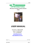
ELECTRONIC ENGINEERING LTD.
DigiDigi-Tool – CUCU-210D
Calibration Unit for
CSB–
CSB–200 Digilon – Microwave barrier
USER MANUAL
P/N 7111202 Rev. B Y.S
1
The Digi-Tool CU-210D is a special calibration and testing unit designed for setting up the CSB-200
Digilon.
The Digi-Tool provides the adjustment of the following signals and parameters:
- Informational messages indication.
- Distance determine and thresholds detecting method.
- Frequency modulation selection.
- Tuning.
- Setting the speed lower limit.
- Setting the speed highest limit.
- Setting the detection range.
- Setting threshold low level.
- Setting threshold high level
Connection:
1.1
Digi-Tool Connection to the CSB-200 Sensor’s is carried out through test connector (RJ-11)
located inside the receiver unit.
1.2
The Digi-Tool’s connections and power supplies are carried out from the CSB-200
1.3
Digi-Tool is connected to the CSB-200 processor and enables recording the memory status of
signals before the installations, and also performs and records new installations.
Control and Indications:
1.4
1.5
The DIGI-TOOL includes three control buttons:
1
«Р» - mode
2
«◄» - less
3
«►» - more
The DIGI-TOOL includes an LCD panel to display the setting mode and testing and setting
parameters.
Operation and setting up the CSB-200:
1.6
To test CSB-200 operation, it is necessary to remove the Receiver top cover and connect the
Digi-Tool to the on board RJ-11 socket, the massage “CSB” should appear on the LCD screen
after the connection.
1.7
In order to set the required mode:
- Press button «P» the inscription «Indic» appears on the LCD screen - that corresponds to the
first mode - MESSAGE INDICATION.
- Using buttons «◄» or «►» choose the required mode,
- The symbol
in left bottom corner of LCD indicates the possibility of entering the chosen mode.
- The second pressing of button «P» will set the mode.
Calibration Modes:
1.8
«Indic» - message indication mode, there are five following messages:
«Pow» - Power supply is lower than normal.
«A!» - Forming of alarm signal.
2
«LL» - Passing of the Low threshold.
«PL» - Passing of the positive threshold.
«HL» - Passing of the High threshold.
1.9
«Method» - Distance determine and thresholds detecting method, there are two options, with the
following messages:
«Auto» - automatic
«Manual» - manual
The selection of a variant or value in this mode is carried out by buttons «◄» or «►».
To return from the mode and installation saving mode back or forward - press button «Р», the
process of installation saving initiates and indicates by the flashing rectangular segment in the right
bottom corner of the LCD.
Notes - At an automatic variant of distance definition and thresholds detection mode, only control of
the established values of these parameters is possible, at manual – you may and should regulate
all the three mentioned modes.
1.10 «Mod Freq» - Frequency modulation setting - There are two options, accompanied by following
messages:
«Main» - major value;
«Altern» - additional value.
Simultaneously with change of CSB-200 Receiver modulation frequency value, it is necessary to
change Transmitter modulation frequency value, by using the jumper marked "F mod" in the
Transmitter unit.
Change of modulation frequency is necessary in case that there is more then one system working
in the same area in order to prevent influence of neighbor's system transmitter radiation on the
Sensor’s operation (See the user manual of the CSB-200 Digilon).
1.11 «Tuning» - Tuning Mode – In this mode there is indication of the receiving signal level in decibels
(Tune from 2 up to 70).
For convenience, the signal partially (20 dB) is displayed by a linear scale, initial value of a linear
scale during tuning changes automatically.
In this mode following messages can be formed.
- «↓Range↑» - overcoming of the signal value the limits of the working range.
- Flashing of numerical value of the coming signal displays extreme values for this signal (defect
of functioning caused by change of external conditions).
The maximal duration of the tuning mode is 5 minutes, after this time the Detector automatically set
back to operation mode.
To enter the Tuning mode again - press button «Mode» once again.
In this mode and after leaving it, there is recording of service data in the Receiver processor
memory, indicated with the flashing rectangular segment in the right bottom corner of LCD screen.
3
1.12 «Min speed» - Mode of setting the lower limit of speed, found out at crossing of DZ, has three
value variants accompanied by messages:
«0.1 m/s»
«0.2 m/s»
«0.4 m/s»
1.13 «Max speed» - Mode of setting the higher limit of speed found out at crossing of DZ, has three
value variants accompanied by messages:
«4 m/s»
«6 m/s»
«10 m/s»
1.14 «Dist Contr» - Working Range Mode, There are four variants of the values accompanied by
messages:
«10-40 m»
«30-140 m»
«120-180 m»
«150-200 m»
The flashing of displayed value shows extreme values of the coming signal (defect of functioning
caused by change of external conditions).
1.15 «Level L» - Low Level Threshold Setting Mode – There are six variants of the values
accompanied by messages:
«-1 dB»
«-2 dB»
«-3 dB»
«-4 dB»
«-5 dB»
«-6 dB»
1.16 «Level P» - High Level Threshold Setting Mode – There are four variants of the values
accompanied by messages:
«+1 dB»
«+2 dB»
«+3 dB»
«+4 dB».
Note – In the «Level L» and «Level P» modes in the lowest line of LCD screen for tuning
convenience the following is displayed: a conditional scale, where threshold’s value - symbol #,
signal value - symbol ↓, breaking up of the small and positive thresholds is signaled by symbol * in
the right bottom corner of the LCD screen.
4