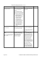
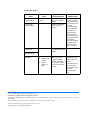
1
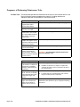
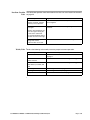
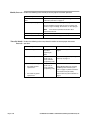
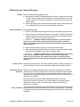
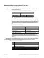
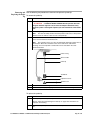
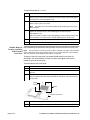
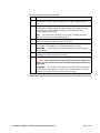
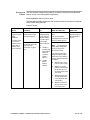
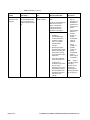
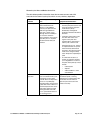
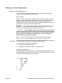
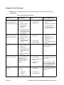
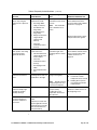
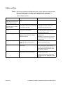
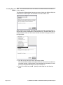
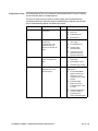
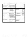
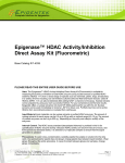
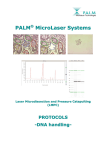
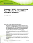
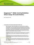
User Bulletin
CATALYST 800/877 Integrated Thermal Cycler
September 9, 1998 (updated 04/2001)
SUBJECT:
Routine Maintenance and Troubleshooting
Overview Periodic maintenance of the CATALYST™ 800 and ABI PRISM® 877 Integrated Thermal
Cycler is essential for optimum performance and prolonged life of hardware
components. There are also some simple tasks you should perform before and after
every run to save time, reagents, and precious samples.
The recommended maintenance tasks and use of the enclosed Pre- and Post-run
Checklist magnet and maintenance log are described in detail in this user bulletin.
Topics in This User This document is an update to your instrument user’s manual and replaces Section 5.
Bulletin The document contains the following topics:
Topic
Frequency of Performing Maintenance Tasks
See page
2
Maintenance for Chemical Reagents
5
Miscellaneous Hardware and Other Maintenance
7
Maintenance of the Probe Tip and Thermal Cycler Plate
10
Maintenance of the Syringes
18
Maintenance of the Cooling System
20
Checklist Magnet and Scheduled Customer Maintenance Logsheet
24
Frequently Asked Questions
26
Utilities and Tests
28
Troubleshooting
32
Frequency of Performing Maintenance Tasks
Pre-Run Tasks The tables below provide more information for the Pre-run tasks listed on the Pre- and
Post-run Checklist magnet (reproduced on page 25), including references to
additional information in this bulletin or in the user’s manual.
Page 2 of 36
Task Description
More information is provided...
Check for sufficient volumes in
reagent bottles (water,
ethanol, buffer, bleach).
under “Maintenance for Chemical Reagents” on page 5.
Check and clean origins
(trenches) as needed.
under “Origin Trenches” on page 7.
Check for clean, empty tube in
position AC4-1 (877) or 300
µL of water (800–instruments
with software earlier than
version 2.0.3).
under “AC4-1 Tube” on page 7.
Compare the locations of
samples and reagents on the
worksurface with the load map
depicted on the monitor.
under “Load Map” in Chapter 2 of the User’s manual.
Check that syringes are firmly
connected and airtight.
under “Maintenance of the Syringes” on page 18.
Check that sufficient space
exists in waste bottle for
generated waste and make
sure the waste line is fastened
securely in place.
under “Waste Bottle” on page 8.
Task Description
Action
Check that liquids are present
in the bottoms of sample and
reagent tubes (no bubbles
should be visible/introduced
by pipetting).
♦
Add missing liquids, referring to the Load Map.
♦
If bubbles are present in a sample or reagent tube,
centrifuge the tube to remove and replace the tube in
the correct position.
Check that cold storage
blocks and racks are properly
seated with white plastic lids
snapped into hinges and
closed.
♦
If a block is not seated properly, press into place firmly.
♦
If a plastic lid is not secured properly, snap it into its
hinge (if needed) and close it properly.
Check that reagent delivery
begins and all temperature
targets are met about 15
minutes after the start of a
run.
This is a check for proper instrument operation as robot
initialization takes about this long on a properly functioning
instrument.
CAUTION The waste bottle should never be more
than half full before a run.
User Bulletin User Bulletin: CATALYST 800/877 Integrated Thermal Cycler
Post-Run Checklist The table below provides more information for the Post-run tasks listed in the checklist
Tasks on page 25.
Task Description
Significance
Check that the final tube
volumes (reagents, samples,
products) are as expected.
Uneven or unexpected volumes may indicate a problem to
be investigated.
Check log file for error
messages.
This information is invaluable in diagnosing instrument
problems.
Note the exact wording of any
error message in the log file
as well as the statements
presented immediately before
and after each error message.
Make sure that the cold
storage lids and the
instrument door are closed.
This reduces condensation on the cold storage blocks.
Weekly Tasks Perform the following tasks weekly to ensure proper instrument operation:
Task Description
More information is provided...
Replace AC4-1 tube
under “Miscellaneous Hardware and Other Maintenance”
on page 7.
Rinse buffer and bleach
bottles and refill
under “Maintenance for Chemical Reagents” on page 5.
Clean external H2O and
EtOH bottles (if needed) and
refill
under “Maintenance for Chemical Reagents” on page 5.
Clean origin trenches
under “Origin Trenches” on page 7.
Run Purge Well Utility
under “Purge Wells Utility” on page 9.
Empty waste bottle
under “Waste Bottle and Tube” on page 8.
User Bulletin User Bulletin: CATALYST 800/877 Integrated Thermal Cycler
Page 3 of 36
Monthly Intervals Perform the following tasks monthly to ensure proper instrument operation:
Task Description
More information is provided...
Remove, clean, and oil TC
plate
under “Monthly Removal, Cleaning, and Oiling of the
Thermal Cycler Plate” on page 12.
Remove/inspect syringes
under “Maintenance of the Syringes” on page 18.
Use the hardware change utility to remove syringes and
check for signs of leakage, discoloration, or worn plunger.
This reference provides information about
Note
expected service life.
Remove/inspect TC lid gasket
under “Thermal Cycler Lid Gasket” on page 8.
Check/fill coolant level
under “Coolant Level” on page 20.
Three/Six Month Perform the following tasks every three/six months to ensure proper instrument
Intervals operation:
Page 4 of 36
Task Description
Interval
More information is provided...
Replace TC lid gasket
Every 3 months
and when
replacing TC
plate
under “Thermal Cycler Lid Gasket” on
page 8.
Replace probe tip
Every 3 months
(PCR only) or
every 6 months
(sequencing only)
under “Removing and Replacing the
Probe Tip” on page 11.
Replace TC plate and gasket
Every 3 months
(PCR only) or
every 6 months
(sequencing only)
♦
Procedure for plate
replacement
♦
Procedure for gasket
replacement
under “Monthly Removal, Cleaning,
and Oiling of the Thermal Cycler
Plate” on page 12 (follow instructions
in note before first procedure).
under “Thermal Cycler Lid Gasket” on
page 8.
User Bulletin User Bulletin: CATALYST 800/877 Integrated Thermal Cycler
Maintenance for Chemical Reagents
Pre-Run Make the following checks before each run:
♦
Make sure that 50 mM Tris/Tween buffer (0.01% Tween™ and 50 mM Tris pH 8.0)
and 2.0% sodium hypochlorite wash bottles in the heated storage area are clean
and full, solutions are clear with no precipitates, and there are no crystals on the
bottle surfaces.
♦
Check that external water and ethanol diluent bottles contain enough fluid for the
run, and their delivery lines are in place and properly connected.
Weekly Maintenance Do the following weekly:
♦
Rinse the Tris/Tween buffer bottle with DI water and refill with 50 mM Tris/Tween.
♦
Rinse the bleach wash bottle with DI water and refill with 2% sodium hypochlorite
solution. Some users may want to replace more often. See “Maintenance of the
Probe Tip and Thermal Cycler Plate” on page 10.
! WARNING ! CHEMICAL HAZARD. Sodium hypochlorite is a corrosive chemical
that can burn and cause serious skin or eye damage. Always work in a fume hood.
Obtain a copy of the MSDS from the manufacturer. Wear appropriate protective eyewear,
clothing, and gloves.
♦
Refill the DI water bottle, cleaning it (if necessary) before refilling.
♦
Refill the ethanol bottle with 95% ethanol, cleaning it (if necessary) before refilling.
See grade recommendation under “Purity of Ethanol” below.
! WARNING ! CHEMICAL HAZARD. Ethanol is a flammable chemical and is irritating
to the skin, eyes, respiratory system. It can cause nerve and liver damage, CNS
depression, nausea, vomiting, and headache. Always work in a fume hood. Obtain a
copy of the MSDS from the manufacturer. Wear appropriate protective eyewear, clothing,
and gloves.
Actions to Avoid Avoid topping off the ethanol, Tris/Tween, or bleach bottles by adding more liquid to a
partially full bottle. This may cause inconsistent reagent concentrations over time.
Why Replacement Is Replace the Tris/Tween solution because it evaporates and concentrates when left
Important standing. Also, Tris/Tween precipitates form. Be sure to remove them from the bottle
lid area as they can clog the probe tip, causing intermittent pipetting volume errors
and sometimes causing right syringe pump overload. The latter is a fatal error and will
abort the run in progress.
Be precise when preparing the sodium hypochlorite solution because the
concentration values are optimal in a very small window. If too concentrated, the
solution will reduce plate life. If the concentration is too dilute, the cleaning
effectiveness is reduced.
Purity of Ethanol We recommend that the ethanol used for line flushing, syringe priming, and cleaning
or drying of surfaces be of molecular biology grade, so as to contain as few impurities
as possible.
User Bulletin User Bulletin: CATALYST 800/877 Integrated Thermal Cycler
Page 5 of 36
Purity of Water We recommend that the DI water used be the highest grade available (e.g., Milli-Q™)
so as to contain as few impurities as possible.
Page 6 of 36
User Bulletin User Bulletin: CATALYST 800/877 Integrated Thermal Cycler
Miscellaneous Hardware and Other Maintenance
General The following are described in this subsection:
♦
AC4-1 tube
♦
Origin Trenches
♦
Waste Bottle
♦
Thermal Cycler Lid Gasket
♦
Purge Well Utility
♦
Troubleshooting Procedure for Start-up Problems
The AC4-1 tube, origin trenches, waste bottle, and thermal cycler lid gasket are
hardware items requiring regular maintenance. The first three items (AC4-1 tube,
origin trenches, and waste bottle) are listed as pre-run checks and also have
maintenance performed on a weekly basis. The thermal cycler gasket requires
maintenance on a monthly basis.
The last two items (Purge Well Utility and Troubleshooting Procedure for Start-up
Problems) are provided to avoid or correct hardware and operational problems.
AC4-1 Tube Purpose of the Tube
The AC4-1 tube wicks water off of the probe tip to ensure accurate mapping of the
worksurface origin.
Weekly Maintenance
For all systems and configurations, change the tube weekly. Then do the following:
♦
For 800 instruments (instruments prior to Ver. 2.0.3 software), add 300 µL of DI water.
♦
For 877 instruments, leave the tube empty.
Why Replacing the Tube Is Important
Replacing the tube will reduce the likelihood of contamination from this source.
Origin Trenches Weekly Maintenance
On a weekly basis, carefully clean the origin trenches with ethanol (see “Purity of
Ethanol” on page 5) and a Kimwipe. Check that no pieces of tissue or lint are left
behind.
The origin trenches are the two L-shaped cutouts near the front and back of the left
Note
side of the worksurface. Water and debris trapped in the trenches interfere with the initialization
routine.
Why Cleaning Trenches Is Important
Keeping the trenches clean is important to ensure accurate mapping of the
worksurface. If the origin trenches are dirty, the system’s capacitance detection
system receives a weak signal, leading to inaccurate mapping of the origin. This is a
critical function for small volume pipetting, which must have accurate probe tip
information to execute properly.
User Bulletin User Bulletin: CATALYST 800/877 Integrated Thermal Cycler
Page 7 of 36
Waste Bottle and Pre-Run
Tube Check that the waste bottle is no more than half full, and the waste tube is securely in
place inside of the bottle. The end of the waste tube should drop only slightly below
the top of the bottle and should not be submerged in waste liquid.
Weekly Maintenance
Empty the waste bottle.
Why Regular Waste Emptying Is Important
Maintenance intervals vary with frequency of use. Some users have relatively modest
sample throughput, and should check waste weekly. For those users with high
throughput, the waste level should be inspected daily, pre-run.
Emptying the waste regularly is essential to prevent waste back up. In addition, the
user can help to prevent vapor lock/gravity lock by ensuring that the waste tubing
follows a gradually continuous downward slope to the bottle, and that the tubing is not
submerged in the waste liquid.
Waste backing up and overflowing onto the robot worksurface during a run is very
Note
likely to contaminate the probe tip, which then contaminates the reactions. If the waste problem
is not corrected before the start of the ensuing run, the robot will fail worksurface mapping and
shut the instrument down, not allowing reaction setup for the run.
Thermal Cycler Lid Monthly Maintenance
Gasket Perform a visual inspection of the lid gasket using the Hardware Change utility to open
the lid. Inspect it carefully, and if any solids are present on the gasket surface, perform
the following cleaning procedure.
Failure to do lid gasket maintenance may increase evaporation of reactions, sample
Note
contamination, and evaporation test failure. The presence of solids on the gasket may indicate
pipetting problems.
To clean the thermal cycler lid gasket:
Step
Action
1
Remove the lid gasket from the thermal cycler lid, removing the set screw if one is
present.
2
Rinse thoroughly with distilled water, and allow the gasket to dry completely at room
temperature.
CAUTION Wiping the gasket dry risks potential scratching by
contaminants (dust, lint, paper particles, etc.).
3
Carefully reinstall the lid gasket on the thermal cycler, using the triangular imprint to
insure correct orientation.
Why Maintaining the Lid Gasket Is Important
Failure to perform lid gasket maintenance may increase evaporation of reactions,
sample contamination, and evaporation test failure.
In addition to inspecting for the presence of solids on the gasket, the user should look
for a uniform impression of the thermal cycler wells. If significant variation is
Page 8 of 36
User Bulletin User Bulletin: CATALYST 800/877 Integrated Thermal Cycler
discovered, replace the gasket. Because the sealing material loses elasticity, the
average expected life of this part is 3 months.
Every Three Months
Replace the lid gasket at this interval and whenever the thermal cycler plate is
replaced.
Purge Wells Utility Weekly Maintenance
Run the Purge Wells Utility from the software as described in the table under “Utilities
and Tests” on page 28.
Why Use of the Utility Is Important
In most cases, an additional cleaning cycle performed on the thermal cycler plate can
help prevent the gradual build up of reaction contaminants. This simple maintenance
task has been proven to extend the life and improve the performance of the plate.
Users routinely running PCR may not need an extra purge.
Troubleshooting This is the procedure recommended under “Troubleshooting” on page 32 when the
Procedure for following dialog box message is presented during operation of the ABI PRISM 877
Start-up Problems system:
Could not connect to ABI PRISM 877 . . . . .wait 10 (15) seconds and try again.
In response to this message, attempt to connect again. If the error dialog box
message is repeated, use the following procedure to connect:
Step
Action
1
Power down both the 877 and the Macintosh.
2
Power up the Macintosh.
3
Find the Terminal application.
This application is represented by a telephone icon and is often located in a folder
with the name “service” in the title.
4
Double-click the Terminal application to open it.
If terminal opens without errors, you will see a blank window and several menu
items along the top menu bar. Proceed with step 7.
5
If there are any errors announced as Terminal opens, quit the Terminal application
and open the Chooser window from the Apple menu.
6
Make AppleTalk inactive and try opening Terminal again. If errors are announced
again, quit this procedure and call ABI Technical Support.
If you have been able to open Terminal without errors, continue with this procedure.
7
Turn on the 877. Within 5 seconds a “boot message” should appear in the open
Terminal window. If nothing appears, quit this procedure and call ABI Technical
Support.
8
Now launch the 877 software from the Macintosh and then start any 877 protocol. If
normal communication has not been re-established by this procedure, call ABI
Technical Support.
User Bulletin User Bulletin: CATALYST 800/877 Integrated Thermal Cycler
Page 9 of 36
Maintenance of the Probe Tip and Thermal Cycler Plate
Introduction The probe tip and thermal cycler plate are considered together for maintenance since
they are replaced simultaneously and require special attention to determine and
maximize the life expectancy.
The maintenance scheduled for these components includes:
Maintenance Task
Interval
Remove/clean/oil TC plate
Monthly
Replace probe tip and
thermal cycler plate
Every 3 months, if
performing PCR
Note
Every 6 months, if
performing sequencing
For optimum performance, follow these recommendations exactly.
The schedule listed above generally provides the best operation but it is difficult to
state an absolute life expectancy for these components since the service life in each
case will vary based on a number of factors, including chemistry and throughput. The
table below lists additional factors which affect the service life. Factors with negative
impact shorten the service life and factors with positive impact lengthen the service
life.
Factors influencing component life:
Positive Impact
Negative Impact
Regularly cleaning reagent bottles
Allowing precipitates to form in reagents
Making fresh reagent stock regularly
Failing to refresh reagent stock
Keeping sodium hypochlorite solution
concentration at 2%
Using over concentrated sodium
hypochlorite solution
Using chemistry-grade sodium hypochlorite
solution of known concentration
Using sodium hypochlorite solution of
unknown concentration and/or quality
The procedures for the replacement of the probe tip and the procedures for the
monthly removal, cleaning, and oiling of the thermal cycler plate are provided in this
section.
Inspecting and Use the following procedure to inspect and clear a probe tip, either before installing a
Clearing the Probe new probe tip or whenever a probe tip is to be reused after it is removed:
Tip
To inspect and clear the probe tip:
Step
Page 10 of 36
Action
1
Check the probe tip against a light source to see if the opening is clear.
2
If the probe tip opening is even partially blocked, blow pressurized air though the tip
and check again.
3
Repeat step 2 until the tip is clear.
4
Wipe the outside of the probe tip with ethanol.
5
If the blockage cannot be cleared, replace the probe tip with a new one.
User Bulletin User Bulletin: CATALYST 800/877 Integrated Thermal Cycler
Removing and Use the following two procedures to remove and replace the probe tip:
Replacing the Probe
To remove the probe tip:
Tip
Step
1
Action
Run the Hardware Change utility.
! WARNING ! PHYSICAL INJURY HAZARD. Do not open the door until
the green indicator light turns off, and do not attempt to defeat the safety
interlock system. It is designed to protect you from movements of the robotic
arm.
2
When the green light on the front of the instrument goes out, open the door.
The robot assembly will be in the Park position. Take notice of this position
Note
and then move the robot for easier access to the probe tip.
3
Unscrew the lower thumbscrew on the probe, and carefully slide the capacitive
sensor out from between the thumbscrews.
The capacitive sensor is a silver, U-shaped clip attached to a black wire as
Note
shown below. Notice the orientation of the sensor and sensor cable before
removing, since it is important to reinstall the sensor and cable in the same
position/orientation.
Probe casing
Sensor Cable
Probe tip
Thumb nut
Capacitive sensor
Thumb screw
4
Unscrew and remove the large thumb nut on the probe.
5
Remove the probe tip by dropping it down and out of the probe casing.
To replace the probe tip:
Step
1
Action
Carefully inspect the new probe tip to make sure it is clear.
Refer to “Inspecting and Clearing the Probe Tip” on page 10 for instructions on
inspection and clearing.
2
Place the new probe tip in the thumb nut, so that it protrudes from the bottom of the
nut.
User Bulletin User Bulletin: CATALYST 800/877 Integrated Thermal Cycler
Page 11 of 36
To replace the probe tip: (continued)
Step
Action
3
Lift the thumb nut containing the probe tip up to the casing, rotating as necessary to
place the square end of the new probe into the probe casing, and carefully tighten
the thumb nut to firm finger-tightness only.
4
Hold the capacitive sensor up against the thumb nut, with one hand, so that the
probe is in the center of the sensor.
Capacitive sensor and cable should be positioned/oriented as they were
Note
before removal.
5
Place the small thumbscrew over the probe with the screw side up, slide it up firmly
against the capacitive sensor, and carefully tighten the thumb screw to
finger-tightness only.
If the sensor/cable assembly rotates while tightening, hold the thumb nut firmly with
one hand and use the other hand to complete tightening of the thumb screw.
Monthly Removal,
Cleaning, and Oiling
of the Thermal
Cycler Plate
6
Return the robot to the Park position.
7
Close the instrument door and press the Resume switch.
Use the following two procedures during monthly service of the thermal cycler plate.
These procedures can also be used to replace a thermal cycler plate at the 3 month/6
Note
month replacement interval and to address failures of 2 µL volume deliveries on the Pipetting
Test (see discussion under “Pipetting Test Failures” on page 36).
To replace a thermal cycler plate, first remove the old thermal cycler plate (as
described in the first procedure) and then use steps 3 through 6 of the second
procedure to install the new plate.
To remove the thermal cycler plate:
Step
Action
1
Run the Hardware Change utility to open the thermal cycler lid.
2
Open the instrument door only after the green light on the front of the instrument
goes out.
3
Loosen the four screws (referring to the figure below) in the thermal cycler plate
with the 5/64-inch Allen wrench provided with the instrument, and carefully set the
screws aside.
Notch
Pointer
Notch
Thermal cycler base
Page 12 of 36
4
Lift the thermal cycler plate off of the base and remove.
5
Continue servicing the thermal cycler plate as described in the following procedure.
User Bulletin User Bulletin: CATALYST 800/877 Integrated Thermal Cycler
To clean and oil the Thermal Cycler Plate:
Step
Action
1
Rinse wells thoroughly with a stream of distilled water from a squeeze bottle, then
force the water out of the wells by shaking the plate vigorously downward over a
sink.
2
Rinse wells thoroughly with a stream of ethanol from a squeeze bottle, again forcing
the liquid out by shaking the plate, and allow the plate to dry completely at room
temperature (see “Purity of Ethanol” on page 5 for information about the
recommended purity of ethanol).
For an alternative to air drying, for users with a centrifuge with swing
Note
buckets, see “Alternative to Air Drying” on page 14.
3
Apply one or two drops of light mineral oil to the back of the thermal cycler plate and
wipe it with a Kimwipe to spread it evenly over the plate.
4
Wipe the top surface of the thermal cycler base with the same tissue to create an
even coating of oil on both the base surface and the back of the plate.
Do not drop oil on the thermal cycler base, as excess oil may
IMPORTANT
cause problems.
5
Place the thermal cycler plate back into position on the thermal cycler base
(referring to the figure in the previous procedure).
6
Tighten the four screws with the Allen wrench.
CAUTION When reinstalling the thermal cycler plate, do not overtighten the
screws. This will strip the screw holes and require replacement of the thermal
cycler block.
If you replace a 96-well thermal cycler plate with a 384-well plate,
IMPORTANT
be sure to use a new lid gasket or one previously used with 384 wells. The rubber
indents on a used gasket must match the thermal cycler plate.
User Bulletin User Bulletin: CATALYST 800/877 Integrated Thermal Cycler
Page 13 of 36
Alternative to Air An alternative to using ethanol and air drying for thermal cycler (TC) plates is to invert
Drying the TC plate onto a paper towel and spin the excess water off in a centrifuge with
swing buckets. This works really well, is faster than waiting for a plate to dry, and
eliminates the possibility of ethanol (or any of the impurities found in lab grade
ethanols) remaining on the plate.
Recognizing
Component
Degradation or
Failure
Importance of Monitoring Component Conditions
To optimize the performance of the instrument, it is important to recognize degradation
or failure of either the probe tip or the thermal cycle plate so that corrective action can
be taken or so they can be replaced. This is especially important in the following
cases:
♦
Whenever such degradation or failure occurs before maintenance or replacement
would be performed as part of the maintenance schedule (see the maintenance
schedule on page 10).
♦
When you are committed to obtaining as long a service life as possible from the
probe tip and thermal cycle plate before replacement.
Monitoring Component Conditions
The condition of the probe tip and thermal cycler plate can be monitored by visual
inspection:
♦
Between regularly scheduled maintenance so as to be aware of incipient
problems developing.
♦
Whenever a review of analyzed data indicates poor quality of 800/877 products.
The analyzed data for products produced on the 800/877 can be examined to see if
Note
there are any cues indicating probe tip or thermal cycler plate degradation.
Visual and Other Cues for Component Degradation or Failure
A number of symptoms will alert you to degradation or failure of the plate and/or probe
tip. These include visual cues such as visible oxidation or other contamination, Teflon
shavings on the worksurface due to the probe hitting the wash station, and overspray.
Other cues, determined by reviewing analyzed data include dropouts, reduced yield,
etc.
Page 14 of 36
User Bulletin User Bulletin: CATALYST 800/877 Integrated Thermal Cycler
Discussion of The most common failures for the probe tip and thermal cycler plate are discussed
Failures here to aid you in maintaining these components.
Probe Tip Failures and Corrective Actions
The table below provides information and corrective actions for the two most common
failure modes of the probe tip:
Table of Failures
Failure
Caused by...
Carry-over of
reagent cocktail
during
distribution
surface conditions on the
outside surface at the
end of the probe tip.
This failure tends
to increase in
frequency as the
tip gets dirty or
with time and
bleach exposure.
poor probe tip position in
the thermal cycler well
when cocktail is
delivered to any given
well.
Characterized
by...
little or no cocktail
being deposited
in one well and
“double delivery”
of cocktail to the
next position.
This is indicated
by:
♦
♦
variable or
unexpectedly
high residual
volume in
cocktail or
sample
tubes, or
variable
pooled
product
volumes
User Bulletin User Bulletin: CATALYST 800/877 Integrated Thermal Cycler
What this looks like...
What to do
on the electrophoresis
data:
Change the tip and
log the change on
the maintenance
record
The gel will exhibit a
low/high pattern of unused
primer in adjoining lanes.
on the machine:
Use the Syringe
Note
Prime Utility (Diagnostics
menu) to look for the
phenomena below.
The probe tip will tend to
hang onto liquid or liquid
will be observed “climbing
the tip” under the following
conditions:
♦
While the tip is at rest
over the waste station
♦
While the syringe is
pushing water through
the tip as it sits over
the waste station in the
rinse mode
♦
While the probe tip is
moving slowly up out
of the small hole (the
wash station)
♦
While the probe tip is
moving slowly up out
of the AC4-1 tube
Page 15 of 36
Table of Failures (continued)
Failure
Caused by...
Major flow
restriction in the
probe tip
contaminants introduced
into the liquid path that
become lodged (often
temporarily) in the probe
tip.
Characterized
by...
What this looks like...
What to do
generally poor
liquid handling.
on the electrophoresis
data:
♦
See “Error
#82” on
page 34 for a
procedure to
evaluate flow
restrictions in
the tip.
♦
Check reagent
bottles as
possible
sources of
particle
contaminant.
Clean as
required.
♦
Check
samples as
possible
sources of
particle
contaminant.
Clean or
improve prep
as required.
The key to recognizing this
failure mode is that it
affects contiguously
positioned reactions,
typically several and
sometimes all samples
on the machine:
♦
Variable or
unexpectedly high
residual volumes in
cocktail or sample
tubes, or variable
pooled product
volumes
♦
Overspray from the
probe tip during waste
delivery or rinsing. The
worksurface around
the waste/wash station
will be wet.
♦
Instrument shutdown,
Pump overload error.
Complete flow
restriction in the probe
tip can cause a
shutdown error on the
right syringe pump as
pressure builds in the
liquid path and slows
the travel of the
syringe.
Page 16 of 36
There is
Note
no need to replace
probe tip if
particles can be
cleared. See
“Inspecting and
Clearing the Probe
Tip” on page 10.
User Bulletin User Bulletin: CATALYST 800/877 Integrated Thermal Cycler
Thermal Cycler Plate and End of Service Life
The table below provides information about the two most common end of life
scenarios for the thermal cycler plate, which are very chemistry dependent:
End of Life
Scenario
Thermal Cycler Plate Usage
Data
End of Service Life
Symptoms/Considerations
Bleach exposure
Applied Biosystems has
demonstrated that PCR
efficiency on the 800/877
thermal cycler plate remains
stable through 100 bleach
clean-ups or purge cycles.
Although there is variability in
the resistance to bleach
plate-to-plate due to the plastic
deposition process, all plates
should meet that 100 cycle
minimum.
♦
When any given well on the
thermal cycler plate reaches end
of life due to bleach exposure,
PCR efficiency drops
dramatically and fragment
production falls below the limit of
detection.
♦
Contiguous wells tend to fail in
the same time frame since
regions of the plate wear
together. When wells begin to
fail, they will continue to fail.
Tracking PCR success, looking
for repeated failures of specific
wells will clearly demonstrate
the point in time when the plate
needs to be changed. Timely
action will prevent a rapid drop in
yield.
♦
Contaminant
deposition
Contaminant deposition tends
to be associated with the cycle
sequencing reaction rather
than with PCR. The deposition
process is very DNA prep
dependent and is characterized
by data that shows evidence of
contaminant peaks that can be
removed by aggressive plate
cleaning but that return with
use on a period that relates to
the cleaning process.
User Bulletin User Bulletin: CATALYST 800/877 Integrated Thermal Cycler
To summarize the above, a
number of symptoms will alert
you to degradation or failure of
the plate and/or probe tip. These
include:
–
reduced yield
–
dropouts
–
visible oxidation or other
contamination
Aggressive plate cleaning removes
contaminant peaks, restoring
productivity for a limited period, but
accelerates the rate of bleach
exposure (the other factor in the
end-of-service life).
Page 17 of 36
Maintenance of the Syringes
Pre-Run Procedure for Inspection
To keep both syringes in optimal condition, perform the following quick inspection:
Step
Action
1
Tighten the glass barrel of the syringes firmly.
2
Tighten the thumbscrew to finger tightness.
3
Inspect both syringes for droplets of water beside the barrels below the Teflon
seals. Moisture there indicates worn seals. Replace the syringe if moisture is found.
Luer fitting
Teflon seal
Barrel
Finger tighten syringes and thumb
screws by turning firmly to the right.
Plunger
Why Pre-Run Syringe Maintenance Is Important
The short list of simple Pre-run actions will help you to regularly take every precaution
necessary to ensure reliable use.
The syringes have a slight tendency to “unscrew themselves” from the luer fittings,
which can cause a failure of the seal between the syringe and the valve. This stops all
liquid movement.
A quick check of the thumbscrew tightness at the bottom of the syringe plunger (not
shown in figure above) will ensure that the plunger/drive shaft connection is secure.
Finally, a quick inspection of the plungers of both syringes, may reveal liquid that has
pushed past or “blown by” the seal. This may indicate that syringe replacement is
necessary.
Page 18 of 36
User Bulletin User Bulletin: CATALYST 800/877 Integrated Thermal Cycler
Monthly To ensure proper operation, do the following monthly:
Maintenance
Step
Action
1
Use the hardware change utility to remove syringes.
2
Check both for signs of leakage, discoloration, or worn plunger tip. Replace a
syringe which exhibits any of these signs.
3
Pull and push syringe plunger and feel for slippage in plunger motion. Replace a
syringe if its plunger does not move smoothly.
Typical life varies with use, but averages about 1 month for the small and 2 months for
the large syringe (assuming daily use).
User Bulletin User Bulletin: CATALYST 800/877 Integrated Thermal Cycler
Page 19 of 36
Maintenance of the Cooling System
Coolant Level Monthly Maintenance
Check the coolant level and add coolant as required. (For details on the cooling
system, refer to the appropriate user’s manual.)
Types of Chillers
The CATALY ST/877 currently uses 2 different types of chillers: the earlier unit using
Syltherm coolant and a newer CFC-free unit using 50% Prestone Long Life Coolant
diluted with distilled water. We recommend that you inspect the chiller in your
instrument at least once a month and, if necessary, add the appropriate amount and
type of coolant according to instructions in this section.
Always use Syltherm (P/N 200988) or Prestone® Extended Life silicate and
IMPORTANT
phosphate-free coolant (P/N N8016186) supplied by Applied Biosystems. With any other
coolant you risk incompatibilities which may damage your instrument.
! WARNING ! HEALTH HAZARD. Prestone Long Life Coolant may cause respiratory
tract, skin, and eye irritation. Syltherm may cause eye irritation. Wear chemical-resistant
gloves and safety glasses. Always use these chemicals in a well-ventilated area. Refer to
the Site Preparation and Safety Guide (P/N 904567) which contains the MSDS with
detailed information regarding these chemicals.
As is stated in the Site Preparation and Safety Guide, “No hazardous waste is
Note
produced as a result of chemicals Applied Biosystems ships with the ABI PRISM® 877.”
Procedures Three procedures are provided for checking and adding coolant:
♦
A procedure for removing the left side panel
♦
A procedure for inspecting the chiller
♦
A procedure for selecting the coolant and filling the chiller
Removing the Left Side Panel
The following illustration shows the rear of the instrument with the three screws and
left side panel being removed. Perform the steps in the following procedure to remove
the panel in order to inspect the chiller unit inside.
Page 20 of 36
User Bulletin User Bulletin: CATALYST 800/877 Integrated Thermal Cycler
! WARNING ! ELECTRICAL SHOCK HAZARD. Severe electrical shock, which could
cause physical injury or death, can result from removal of any outside instrument panels
while the high-voltage power supply is operating. Turn off the power supply to the
instrument, unplug the power cord, and wait at least 1 minute before removing outside
panels.
To remove the left side panel
Step
Action
1
Turn off all power to the instrument and take the other steps listed in the Warning
above before proceeding.
2
Remove the three screws on the back holding the left side panel in place (In some
cases you may also need to loosen the two screws holding the top cover.)
3
Pull the sides of the panel first toward you, then up to release it from the body of the
instrument, and then set it aside.
Inspecting the Chiller
To determine which coolant to use:
Step
1
Action
Inspect the chiller, and compare it to the two shown in the figure below to identify
the type of chiller installed on your instrument.
If your chiller looks like the unit on the left you must use Syltherm coolant. If it looks
like the unit on the right, use 50% Prestone Long Life Coolant.
Syltherm chiller
cap
fill line
50% Prestone Long Life Coolant chiller
cap
Syltherm must never be mixed with water. Prestone Long Life
IMPORTANT
Coolant must be diluted 1:1 with distilled water.
2
Use the appropriate step for your chiller:
a.
If your chiller requires Syltherm, check the level of coolant in the overflow
bottle.
The bottle should be at least 2/3 full of Syltherm, and the tube should be
suspended in the Syltherm approximately 1/2 inch from the bottom. These
conditions prevent water intake, as water will separate from Syltherm and move
to the bottom of the bottle. If the tube touches bottom, it will pull water instead
of coolant.
b.
If your chiller requires 50% Prestone Long Life Coolant, unscrew the cap on the
chiller (you may need to use a medium-size adjustable wrench) and look
inside. The coolant level should be within an inch of the top, near the bottom of
the interior threads.
User Bulletin User Bulletin: CATALYST 800/877 Integrated Thermal Cycler
Page 21 of 36
To determine which coolant to use: (continued)
Step
3
Action
If your chiller unit has an adequate amount of coolant, screw on the cap to finger
tightness, and replace the side panel.
You are now finished with the cooling system inspection.
4
If you need to add coolant to the chiller, proceed to the procedure immediately
below (Selecting Coolant and Filling the Chiller).
Selecting Coolant and Filling the Chiller
Select and prepare the appropriate coolant as follows.
To use Syltherm and fill the reservoir:
Step
1
Action
Remove the cap from the overflow bottle, and pour undiluted Syltherm directly from
the shipping container into the overflow bottle until it is approximately 2/3 full.
CAUTION
Do not allow water to contaminate the Syltherm.
2
If water or debris are visible in the overflow bottle, empty it, rinse with 100% ethanol
and refill.
3
Recap the bottle, tightening it to finger-tightness.
4
Check the plastic tube from the overflow bottle to the chiller to ensure that it is firmly
attached and suspended in the Syltherm approximately 1/2 inch from the bottom of
the overflow bottle.
5
Replace the side panel and the three screws in the back firmly tightening them with
a screwdriver.
To prepare 50% Prestone Long Life Coolant and fill the reservoir:
Step
Page 22 of 36
Action
1
Mix 100 mL distilled water and 100 mL Prestone Long Life Coolant.
2
Pour in the 50% Prestone Long Life, filling it up to the bottom of the interior threads.
3
Replace the coolant reservoir cap, tightening it to finger-tightness.
User Bulletin User Bulletin: CATALYST 800/877 Integrated Thermal Cycler
To prepare 50% Prestone Long Life Coolant and fill the reservoir: (continued)
Step
4
Action
Replace the side panel and the three screws in the back. Tighten the screws firmly
with a screwdriver.
Why Coolant Be sure to use only coolant sold by Applied Biosystems. The coolant we supply is
Maintenance Is tested for additives to insure compatibility with our chemistries.
Important
Very slow leaks in the coolant flowpath can, over time, lead to a failure of coolant flow
through the system, causing an inability to reach and hold cooling targets. Leak rates
can vary with changes in the lab environment, and are usually invisible. Any liquid
leaking out of the system may not be distinguishable from water condensed out of the
air, and is absorbed by the cooling system insulation.
User Bulletin User Bulletin: CATALYST 800/877 Integrated Thermal Cycler
Page 23 of 36
Checklist Magnet and Scheduled Customer Maintenance Logsheet
Where to Place the Place the Pre- and Post-run Checklist magnet on the front of the instrument as shown
Checklist and in the figure below. A copy of this checklist is on the next page.
Logsheet Enclosure
The Scheduled Customer Maintenance Logsheet comes enclosed in a clear, plastic
envelope with magnets attached. (Enough copies of the logsheet are provided to
cover five years of operation.) Attach the sleeve inside the instrument as shown in the
figure below.
To ensure a proper record of instrument maintenance, we recommend that the date be
Note
entered on the logsheet for each maintenance item completed.
Attach the Pre- and Post-Run Checklist magnet to the right front panel.
Attach the Scheduled Customer Maintenance Logsheet inside the instrument.
Page 24 of 36
User Bulletin User Bulletin: CATALYST 800/877 Integrated Thermal Cycler
Pre- and Post-Run
Checklist
User Bulletin User Bulletin: CATALYST 800/877 Integrated Thermal Cycler
Page 25 of 36
Frequently Asked Questions
Questions and The following table lists many questions likely to be raised using the instrument.
Discussion
Table of Frequently Asked Questions
Question
Action/Reason
Why/when might I do
this?
Reference/Additional Info
What do I do if the robot
shuts down in the middle
of a run with reactions
inside the thermal cycler?
♦
♦
Power failure
♦
♦
Fatal robot error
during protocol
Reactions will be lost
(pipetted by robot to
waste).
♦
See utility table (page 28).
♦
Manual recovery of
reactions is possible only
for 96-well TC plate.
♦
See syringe procedure
(page 18).
♦
See probe tip and TC
plate procedure
(page 10).
See TC gasket procedure
(page 8).
How do I access syringes,
probe tip, TC plate or
gasket on the instrument?
How do I fill external
bottles?
What do I do if I see air
bubbles in the syringes?
How and when do I test
the robot
Page 26 of 36
♦
Run Reaction
Remove and Purge
utility
If cause of abort is
power failure, no
other action is
required
♦
If cause of abort is
robot error, see error
code troubleshooting
table (page 32).
♦
Run Hardware
Change Utility to
replace components.
♦
Perform a
Comprehensive Test
to verify integrity of
change.
♦
During Routine
maintenance
♦
To investigate
possible problem
♦
♦
During Robot setup
See “Diluent and Waste
Bottles...” in Chapter 2 of the
User’s manual.
Run Syringe Prime Utility,
observe and compare
operation to the
description in the right
column (normal air
behavior).
♦
During syringe
priming activity
♦
After refilling external
bottles
All air intake to large syringe
should stop after completion of
2nd full stroke
♦
After replacing
syringes
Small air bubble may lodge in
100 µL syringe during ethanol
prime, but should be pushed
out during water prime
Run one of the following
tests:
♦
During Routine
maintenance
See “Basic Test” in the table
under “Comprehensive Tests”
on page 31.
♦
To investigate
possible problem
a.
Remove tubes, dump,
clean, and refill
bottles.
b.
Replace tube,
positioning it properly
at the bottom of the
bottle.
c.
Run Syringe Prime
utility.
♦
Basic
♦
Temperature
♦
Pipetting
♦
Comprehensive
User Bulletin User Bulletin: CATALYST 800/877 Integrated Thermal Cycler
Table of Frequently Asked Questions (continued)
Question
Action/Reason
What do I need to do if I
plan to stop using the
instrument for a period of
time?
Clean and prepare the
instrument to sit idle:
What do I need to do
when I plan to start using
the instrument after
significant idle time?
Should I leave the
instrument on between
runs?
a.
Run Purge Wells
utility (2% bleach).
b.
Run Bleach Line
Purge utility.
c.
Run Ethanol Line
Purge utility.
d.
Empty and clean the
reagent bottles
(external and
internal).
e.
Clean the
worksurface before
start-up.
Preparation of instrument
to start active use:
a.
Fill external/internal
reagent bottles with
fresh solutions
b.
Clean the
worksurface before
start-up
c.
Run Syringe Prime
Utility
d.
Run Comprehensive
Test
Make decision after
reviewing benefit and cost
information to the right.
Why/when might I do
this?
When I plan not to use the
instrument for two weeks
or more.
Two weeks idle
Note
time is maximum w/ no
action.
Ethanol replacement of water
will prevent bacteria growth
When I plan to use the
instrument again after
shutting it down as listed
above.
More information is presented
for the utilities and tests listed
in the second column under
“Utilities and Tests” on
page 28.
When the instrument is
being used regularly.
Benefits of leaving on:
Benefits must be
Note
weighed against the cost
of power consumption.
Should I try to run the
instrument Friday night
and pick up samples
Monday morning?
No.
Does it matter whether I
turn the instrument on
before the computer or
vice-versa?
By design, it should not
matter.
Reference/Additional Info
More information is presented
for the utilities listed in the
second column under “Utilities
and Tests” on page 28.
Never, since the Risks of
enzyme activity,
condensation, and
evaporation all increase
after 36 hours.
♦
Ice formed on chiller
components does not melt
♦
Avoiding Start up errors
associated with software
communication
The best way to remove
products is within 24 hours of
the beginning of run.
In practice, it is best that
the 877 application not be
launched until 15 seconds
after the instrument has
been powered up.
User Bulletin User Bulletin: CATALYST 800/877 Integrated Thermal Cycler
Page 27 of 36
Utilities and Tests
Utilities Utilities are available from the Diagnostic Menu in the 877 software and from the Main
Menu in the 800 software. The utilities are designed to set up and maintain the
instrument. The specific use of each utility is described in the table below.
Table of Utilities and Tests
Name of Utility
Action or Actions
Frequency/Reason
Purge Wells
Cleans the Thermal Cycler Reaction
Wells.
Scheduled maintenance once a week.
Removes reactions from the thermal
cycler, delivers them to waste, and cleans
the Thermal Cycler wells.
Use in case of a power fail or other abort
of robot protocol while reactions are
contained in the Thermal Cycler.
Primes the Syringe Pump plumbing
system from external bottles.
Use this Utility after filling external bottles.
Decontaminates the Syringe Pump
plumbing system with the 2% sodium
hypochlorite solution.
Use if there is any evidence of product
contamination.
Ethanol Line Purge
Fills the Syringe Pump plumbing system
w/ 95% ethanol to prevent bacteria
growth.
Used when the instrument will be shut
down for two weeks or more.
Cycling Profile
Tests and edits thermal profiles without
robot activity.
Some combinations of target and hold
times (especially very short hold times (~5
sec) may not run without system errors
and should be tested here before use in
the chemistry notebook.
Worksurface Initialization
Maps the X/Y/Z coordinates of the cold
storage rack location on worksurface.
Used when system requests (with
dialogue box message).
This utility will not remove any
residual liquid in the plate.
Reaction Remove and Purge
This utility removes residual
liquid in the plate.
Syringe Prime
Bleach Line Purge
Use this Utility first if System has been
idle for two weeks or more.
Used before the Ethanol Line Purge when
the instrument will be shut down for two
weeks or more.
Frequent system requests for this utility
should be reported to Applied Biosystems
Service.
Page 28 of 36
User Bulletin User Bulletin: CATALYST 800/877 Integrated Thermal Cycler
Table of Utilities and Tests (continued)
Name of Utility
Action or Actions
Frequency/Reason
Hardware Change
Prepares the system for component
replacement.
See recommendations beside each item
below.
Some reasons for removal/replacement of
components are listed below:
Probe Tip
Right Syringe Pump Overload Error
(possible flow restriction in probe tip)
Scheduled Maintenance:
Replace every 3-6 months.
TC Plate
Scheduled Maintenance:
Once monthly - clean & Oil.
Every 3-6 months - replace.
TC Gasket
Scheduled Maintenance:
Monthly - inspect and clean if necessary.
Every 3 months - replace.
Syringe
Scheduled Maintenance:
Before each run - tighten to valve.
Monthly - remove & inspect.
User Bulletin User Bulletin: CATALYST 800/877 Integrated Thermal Cycler
Page 29 of 36
Accessing Tests and Note The instructions below are for 877 software. For similar instructions for the 800, see
Utilities the User’s Manual.
The Diagnostics Window below allows you to access all tests and utilities. Initially, the
window shows the description and estimated run time of the Basic Test.
When another test is selected, the window changes to provide a brief explanation of
what the test or utility accomplishes, the duration of the run, and fields where you can
modify conditions of the run. All the tests available are shown in the pop-up menu of
the figure below:
♦
Click Run to start the test or Cancel to close the window.
The Load and Build windows are displayed while test commands are loaded into
instrument memory. If the Macintosh is not connected to the instrument, an error
message is displayed indicating that the test cannot be run.
♦
Page 30 of 36
To cancel a running test, press
menu.
a. (period) or select Stop from the Chemistry
User Bulletin User Bulletin: CATALYST 800/877 Integrated Thermal Cycler
Comprehensive Tests The Comprehensive Tests are available from the Diagnostic Menu in the 877 software
and from the Main Menu in the 800 software.
The tests are used primarily to confirm system integrity after the performance of
scheduled maintenance and to do specific troubleshooting as required. For the latter,
see the Troubleshooting Section that follows this section.
Name of Test
Function
Time
Description of Test
Comprehensive Test
Performs a complete Test
of the robot.
1 hr
Includes:
Basic Test
Temperature Test
Pipetting Test
Exercises the robot
components,
communication, and
Capacitance Sense
System (as listed to the
right).
Exercises temperature
control as listed to the
right.
Measures the accuracy of
liquid deliveries to the
Thermal Cycler.
User Bulletin User Bulletin: CATALYST 800/877 Integrated Thermal Cycler
5 min
10 min
40 min
♦
Basic Test
♦
Temperature Test
♦
Pipetting Test
♦
Limit Switches for X/Y/Z
robot range
♦
TC Lid Mechanism
♦
Syringe Pump
Communication
♦
Capacitance Sense
System (metal and
liquid level detection)
♦
Thermal cycler heating
and cooling
♦
Cold storage cooling
♦
Heated storage heating
Test report contains 3
subsections:
♦
Pre-heat Well Depth
Report: 2/5/10/15 µL
deliveries w/ small
syringe; 20 µL w/ Large
Syringe
♦
Post-heat Depth
Report: measures
evaporation from same
TC wells
♦
Fluid Removal Report:
measures ability of
Large Syringe to
remove liquid effectively.
Page 31 of 36
Troubleshooting
Overview The following table provides a summary of actions that the user can take to expedite
recovery from specific system failure modes. The failure modes are organized into
these groups:
♦
Errors reported during a chemistry protocol or run
♦
Failures reported during Comprehensive Tests
Error Messages This table provides a list of actions with accompanying descriptions/causes as well as
pertinent references.
Table of Error Message Information
Event
Action
Description/Cause
Reference
Error #11
Note position of probe tip on
worksurface and do the
following:
Robot hardware error.
See “Basic
Test” in the
table under
“Comprehen
sive Tests”
on page 31.
“Profile not completed in 60
seconds”
Error #22
“Compliance switch triggered”
♦
Manually move the robot
arm back to the wash
station.
♦
Run the Basic Test.
♦
Report the Basic Test
Failures to Service
Note position of the probe tip.
This error can be caused by a
missing tube.
Failure of robot to find tube
bottom or worksurface with
optical switch.
If probe tip has just been
changed, do the following:
♦
Check that sensor is firmly
attached (see “Removing
and Replacing the Probe
Tip” on page 11).
♦
Run Pipetting Test (see
“Comprehensive Tests” on
page 31).
If error recurs, call service.
Error #23
Action depends on tip position:
“Compliance Switch triggered
during profile motion”
♦
if reagent bottle, remove
bottle cap seal and proceed.
♦
if cold storage, check tube
height, run Worksurface
Initialization Utility.
♦
if thermal cycler, call
service.
Page 32 of 36
Robot encoders safety switch
when the probe tip hits an
obstacle.
This means robot is out of
position OR tubes are riding
high OR reagent bottle caps
are too tall.
User Bulletin User Bulletin: CATALYST 800/877 Integrated Thermal Cycler
Table of Error Message Information (continued)
Event
Action
Description/Cause
Error #24
Most common occurrence of this
error is failure of the liquid level
search during the pipetting test.
Surface detection failure.
“Compliance Switch triggered
during search motion”
Error #35
♦
Remove and reinstall the
probe tip and run the test
again.
♦
Call service. They will guide
you to re-enter data from
service notebook.
♦
Run the Worksurface
Initialization Utility.
“Robot needs calibration”
Error #37
(sometimes reported as
“unknown”)
“target temperature not
achieved”
The primary concern is to know
which target is not being
reached.
Review graph file, turn on target
information, compare to actual,
and then do the following:
♦
Run Cycling Profile utility
with same targets and hold
times to see if error returns.
♦
Call service if error returns.
Error #80
Do the following:
“no pump communication”
♦
Turn 877 off/on, restart Mac.
♦
Run Basic Test.
♦
If pump communication fails,
call service.
User Bulletin User Bulletin: CATALYST 800/877 Integrated Thermal Cycler
Reference
Cold storage rack data or
temperature sensor calibration
data has been lost.
See
“Worksurface
Initialization”
in the table
under
“Utilities and
Tests” on
page 28.
♦
See “Cycling
Profile” in the
table under
“Utilities and
Tests” on
page 28.
One or more target
temperatures is not
reached in the allowed
time.
Generally, these
Note
errors will not abort the run.
Indicates the failure of the
robot system CPU to
communicate with the syringe
pump assembly.
Page 33 of 36
Table of Error Message Information (continued)
Event
Action
Description/Cause
Error #82
Since this error can be caused
by flow restriction in the probe tip
or line, do the following to
evaluate.
Indicates the failure of the
large syringe to meet speed
requirement.
“right pump overload”
Reference
Run the Hardware Change
Utility, remove the Large Syringe,
then press the “resume” switch:
♦
If pump overload error does
NOT repeat, put the same
large syringe back on,
replace the probe tip if it is
occluded, and run the
Syringe Prime utility.
See “Inspecting and
Clearing the Probe Tip” on
page 10 for tip inspection
and clearing procedure.
♦
Error # 104
“z up limit switch”
If the pump overload error
repeats with the large
syringe removed, call
service.
Move the robot arm manually to
the wash station, push down 2-4
cm, and start protocol again.
Indicates Z home switch
search error at beginning of
run.
If this error occurs at any other
time during a protocol, call
service.
Error indicated by following
dialog:
“Could not connect to ABI PRISM
877. . . . .wait 10 (15) seconds
and try again.”
Try again. If the error dialog box
message to the left repeats
again, try the procedure listed
under “Troubleshooting
Procedure for Start-up
Problems” on page 9:
Communication cables can be
loose. Two identical cables
should be connected from the
printer and modem ports on
the Macintosh to ports labeled
similarly on the 877. Please
check connection integrity.
Power down of the 877
instrument is necessary to
clear communication if the last
protocol attempted ended with
an abort condition announced
by an error message.
Attempting to run an 877
protocol within 5-10 seconds
of turning on the instrument
will cause the dialog box error
message presented to the left.
Page 34 of 36
User Bulletin User Bulletin: CATALYST 800/877 Integrated Thermal Cycler
Comprehensive Test Basic Test Failures
Failures
Event
Action
Description/Cause
Reference/
Additional
Info
Lid Movement
Failure
Call service and report
the specific failure.
Open/Close or
Clamp/Unclamp does
not function.
Pump
communication link
Failure
Do the following:
Indicates failure of the
robot system CPU to
communicate with the
syringe pump
assembly.
See “Basic
Test” in the
table under
“Comprehensive Tests”
on page 31.
Indicates failure of the
robot to find the limit
switches.
Same
reference as
above
Indicates failure of the
surface detection
system.
Same
reference as
above
Action
Description/Cause
Reference/
Additional
Info
Take the actions below
for any of the events to
the left:
The target
temperatures for each
element have not been
met in the allowable
time.
Robot Arm Failure
Liquid Level Sense
Failure
♦
Turn the 877
off/on.
♦
Run the Basic Test
again.
♦
If the failure
repeats, call
service
Do the following:
♦
Turn the 877
off/on.
♦
Run the Basic Test
again.
♦
If failure repeats,
call service.
Do the following:
♦
Turn the 877
off/on.
♦
Run the Basic Test
again.
♦
If failure repeats,
call service.
Temperature Test Failures
Event
♦
Lid temp failure
♦
Thermal Cycler
failure
♦
Heated Storage
failure
♦
Left Cold
Storage failure
♦
Right Cold
Storage failure
♦
Look at graph and
log file to find the
specific failure.
♦
Do you find any
unexpected
heating or cooling
value?
♦
Call service and
report specific
errors or
unexpected values.
User Bulletin User Bulletin: CATALYST 800/877 Integrated Thermal Cycler
Page 35 of 36
Pipetting Test Failures
Event
Small syringe
deliveries failed.
Action
Description/Cause
Inspect or change
syringes.
Indicates the probable
failure of the 100 µL
syringe.
Large syringe
deliveries failed.
Indicates the probable
failure of the 5 ml
syringe.
Reference/
Additional Info
If only 2 µL volumes
fail, this is often a
false failure related
to surface tension in
TC wells.
Chemistry results
may not degrade.
Cleanliness of
Thermal Cycler
Plate may affect
surface tension. For
cleaning procedure,
see “Monthly
Removal, Cleaning,
and Oiling of the
Thermal Cycler
Plate” on page 12.
Small syringe lid seal
volumes fail.
Replace gasket.
Indicates poor sealing
of the thermal cycler lid
gasket.
Do the following:
Indicates the probable
failure of the 5 ml
syringe or that the
thermal cycler wells
are not clean (reaction
residue or dirt may be
present).
Large syringe lid
seal volumes fail.
Empty well with large
syringe fail.
♦
Replace 5 mL
syringe.
♦
Clean or
replace TC
plate.
If one or two of 22
tested wells report
failure, ignore the
failure.
If more than two of
22 tested wells
report failure, take
the action
described to the
left.
© Copyright 2001, Applied Biosystems. All rights reserved.
For Research Use Only. Not for use in diagnostic procedures.
ABI PRISM, the ABI PRISM design, and Applied Biosystems are registered trademarks of Applera Corporation or its subsidiaries in the U.S. and certain
other countries.
ABI is a trademark of Applera Corporation or its subsidiaries in the U.S. and certain other countries.
All other trademarks are the sole property of their respective owners.
P/N 4306519 Rev. B; Stock Number 280802-002