1
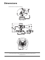
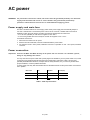
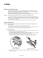
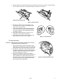
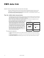
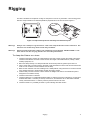
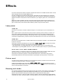
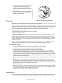
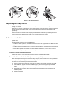
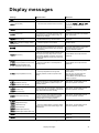
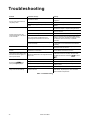
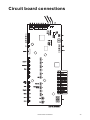
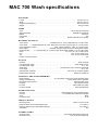
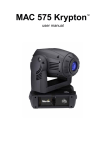
MAC 700 Wash user manual Dimensions All measurements are expressed in millimeters 285 120° 120° 675 365 12.5°xx° 66 66° xx°12.5 656 515 390 143 Min. c/c 530 450 270° 270° 565 © 2006 Martin Professional A/S, Denmark. All rights reserved. No part of this manual may be reproduced, in any form or by any means, without permission in writing from Martin Professional A/S, Denmark. Printed in Denmark. P/N 35000185, Rev. C Safety information Warning! This product is for professional use only. It is not for household use. This product presents risks of lethal or severe injury due to fire and heat, electric shock, ultraviolet radiation, lamp explosion, and falls. Read this manual before powering or installing the fixture, follow the safety precautions listed below and observe all warnings in this manual and printed on the fixture. If you have questions about how to operate the fixture safely, please contact your Martin dealer or call the Martin 24-hour service hotline at +45 70 200 201. PROTECTION FROM ELECTRIC SHOCK • Disconnect the fixture from AC power before removing or installing the lamp, fuses, or any part, and when not in use. • Always ground (earth) the fixture electrically. • Do not use the fixture with a damaged power cable or power plug. • Use only power cable specified as extra hard usage • Do not attempt to bypass fuses. Replace defective fuses with ones of the specified type and rating only. • Use only a source of AC power that complies with local building and electrical codes and has both overload and ground-fault (earth-fault) protection. • Do not expose the fixture to rain or moisture. • Refer any service operation not described in this manual to a qualified technician. LAMP SAFETY • Do not operate the fixture with missing or damaged covers, shields, lenses or ultraviolet screens. • A hot discharge lamp is under pressure and can explode without warning. Allow the fixture to cool for at least 45 minutes and protect yourself with safety glasses and gloves before replacing the lamp or servicing the fixture internals. • Do not stare directly into the light output. Never look at an exposed lamp while it is lit. • Replace the lamp if it becomes visually deformed, damaged or in any way defective • Replace the lamp at the latest when it reaches the limit of its average life as specified in this manual or by the lamp manufacturer. • Install only an approved lamp. • If the quartz envelope of a discharge lamp is broken, the lamp releases a small quantity of mercury and other toxic gases. If a discharge lamp explodes in a confined area, evacuate the area and ventilate it thoroughly. Wear nitrite gloves when handling a broken discharge lamp. Treat broken or used discharge lamps as hazardous waste and send to a specialist for disposal. PROTECTION FROM BURNS AND FIRE Danger! Intense heat. Avoid contact by persons and materials. The exterior of the fixture can get very hot – up to 160° C (320° F). Allow the fixture to cool for at least 45 minutes before handling. Prolonged exposure to an unshielded lamp can cause eye and skin burns. • Do not attempt to bypass thermostatic switches or fuses. Replace defective fuses with ones of the specified type and rating only. • Keep all combustible materials (for example fabric, wood, paper) at least 0.5 meters (20 inches) away from the fixture. Keep flammable materials well away from the fixture. • Do not illuminate surfaces within 1.2 meters (42 inches) of the fixture. • Provide a minimum clearance of 0.1 meters (4 inches) around fans and air vents. • Do not place filters or other materials over the lens. • The exterior of the fixture becomes hot. Allow the fixture to cool for at least 45 minutes before handling. • Do not use the fixture if any cable, component or cover is damaged, cracked or deformed. • Do not modify the fixture in any way not described in this manual. • Install only genuine Martin parts. • Do not operate the fixture if the ambient temperature (Ta) exceeds 40° C (104° F). PROTECTION FROM INJURY DUE TO FALLS AND WHILE LIFTING • Do not lift or carry the fixture alone. • When installing the fixture above ground level, verify that all supporting structures, fasteners and lifting equipment can hold at least 10 times the weight of all installed devices. • Check that all external covers and rigging hardware are securely fastened and use an approved means of secondary attachment such as a safety cable. • Block access below the work area and work from a stable platform whenever installing, servicing or moving the fixture. Disposing of this product Martin products are supplied in compliance with Directive 2002/96/EC of the European Parliament and of the Council of the European Union on WEEE (Waste Electrical and Electronic Equipment), as amended by Directive 2003/108/EC, where applicable. Help preserve the environment! Ensure that this product is recycled at the end of its life. Your supplier can give details of local arrangements for the disposal of Martin products. Contents Introduction . . . . . . . . . . . . . . . . . . . . . . . . . . . . . . . . . . . . . . . . . . . . . . . . . . . . . . . . . . . . . . . . . . . . . . . . 6 Unpacking . . . . . . . . . . . . . . . . . . . . . . . . . . . . . . . . . . . . . . . . . . . . . . . . . . . . . . . . . . . . . . . . . . . . . . . . 6 Using for the first time . . . . . . . . . . . . . . . . . . . . . . . . . . . . . . . . . . . . . . . . . . . . . . . . . . . . . . . . . . . . . . . 6 AC power . . . . . . . . . . . . . . . . . . . . . . . . . . . . . . . . . . . . . . . . . . . . . . . . . . . . . . . . . . . . . . . . . . . . . . . . . . 7 Power supply and main fuse . . . . . . . . . . . . . . . . . . . . . . . . . . . . . . . . . . . . . . . . . . . . . . . . . . . . . . . . . . 7 Power connection . . . . . . . . . . . . . . . . . . . . . . . . . . . . . . . . . . . . . . . . . . . . . . . . . . . . . . . . . . . . . . . . . . 7 Lamp . . . . . . . . . . . . . . . . . . . . . . . . . . . . . . . . . . . . . . . . . . . . . . . . . . . . . . . . . . . . . . . . . . . . . . . . . . . . . . 8 About the discharge lamp . . . . . . . . . . . . . . . . . . . . . . . . . . . . . . . . . . . . . . . . . . . . . . . . . . . . . . . . . . . . 8 Lamp replacement . . . . . . . . . . . . . . . . . . . . . . . . . . . . . . . . . . . . . . . . . . . . . . . . . . . . . . . . . . . . . . . . . . 8 DMX data link . . . . . . . . . . . . . . . . . . . . . . . . . . . . . . . . . . . . . . . . . . . . . . . . . . . . . . . . . . . . . . . . . . . . . 10 Tips for reliable data transmission . . . . . . . . . . . . . . . . . . . . . . . . . . . . . . . . . . . . . . . . . . . . . . . . . . . . . 10 Rigging . . . . . . . . . . . . . . . . . . . . . . . . . . . . . . . . . . . . . . . . . . . . . . . . . . . . . . . . . . . . . . . . . . . . . . . . . . . 11 Control panel . . . . . . . . . . . . . . . . . . . . . . . . . . . . . . . . . . . . . . . . . . . . . . . . . . . . . . . . . . . . . . . . . . . . . 12 Menu navigation . . . . . . . . . . . . . . . . . . . . . . . . . . . . . . . . . . . . . . . . . . . . . . . . . . . . . . . . . . . . . . . . . . DMX address and protocol . . . . . . . . . . . . . . . . . . . . . . . . . . . . . . . . . . . . . . . . . . . . . . . . . . . . . . . . . . Tailoring performance . . . . . . . . . . . . . . . . . . . . . . . . . . . . . . . . . . . . . . . . . . . . . . . . . . . . . . . . . . . . . . Readouts . . . . . . . . . . . . . . . . . . . . . . . . . . . . . . . . . . . . . . . . . . . . . . . . . . . . . . . . . . . . . . . . . . . . . . . . Service messages . . . . . . . . . . . . . . . . . . . . . . . . . . . . . . . . . . . . . . . . . . . . . . . . . . . . . . . . . . . . . . . . . Manual control . . . . . . . . . . . . . . . . . . . . . . . . . . . . . . . . . . . . . . . . . . . . . . . . . . . . . . . . . . . . . . . . . . . . Service utilities. . . . . . . . . . . . . . . . . . . . . . . . . . . . . . . . . . . . . . . . . . . . . . . . . . . . . . . . . . . . . . . . . . . . 12 12 12 13 14 14 14 Effects . . . . . . . . . . . . . . . . . . . . . . . . . . . . . . . . . . . . . . . . . . . . . . . . . . . . . . . . . . . . . . . . . . . . . . . . . . . . 16 Lamp power . . . . . . . . . . . . . . . . . . . . . . . . . . . . . . . . . . . . . . . . . . . . . . . . . . . . . . . . . . . . . . . . . . . . . . Fixture reset. . . . . . . . . . . . . . . . . . . . . . . . . . . . . . . . . . . . . . . . . . . . . . . . . . . . . . . . . . . . . . . . . . . . . . Dimming and strobe. . . . . . . . . . . . . . . . . . . . . . . . . . . . . . . . . . . . . . . . . . . . . . . . . . . . . . . . . . . . . . . . Cyan, magenta, yellow and color temperature control . . . . . . . . . . . . . . . . . . . . . . . . . . . . . . . . . . . . . Color wheel . . . . . . . . . . . . . . . . . . . . . . . . . . . . . . . . . . . . . . . . . . . . . . . . . . . . . . . . . . . . . . . . . . . . . . Beam shaper . . . . . . . . . . . . . . . . . . . . . . . . . . . . . . . . . . . . . . . . . . . . . . . . . . . . . . . . . . . . . . . . . . . . . Effect macros. . . . . . . . . . . . . . . . . . . . . . . . . . . . . . . . . . . . . . . . . . . . . . . . . . . . . . . . . . . . . . . . . . . . . Zoom . . . . . . . . . . . . . . . . . . . . . . . . . . . . . . . . . . . . . . . . . . . . . . . . . . . . . . . . . . . . . . . . . . . . . . . . . . . Pan and tilt. . . . . . . . . . . . . . . . . . . . . . . . . . . . . . . . . . . . . . . . . . . . . . . . . . . . . . . . . . . . . . . . . . . . . . . Pan/tilt speed and effects speed channels . . . . . . . . . . . . . . . . . . . . . . . . . . . . . . . . . . . . . . . . . . . . . . 16 16 16 17 17 17 17 17 17 17 Optical configuration . . . . . . . . . . . . . . . . . . . . . . . . . . . . . . . . . . . . . . . . . . . . . . . . . . . . . . . . . . . . . . 19 Color wheel . . . . . . . . . . . . . . . . . . . . . . . . . . . . . . . . . . . . . . . . . . . . . . . . . . . . . . . . . . . . . . . . . . . . . . 19 Routine maintenance . . . . . . . . . . . . . . . . . . . . . . . . . . . . . . . . . . . . . . . . . . . . . . . . . . . . . . . . . . . . . . 20 Tilt lock. . . . . . . . . . . . . . . . . . . . . . . . . . . . . . . . . . . . . . . . . . . . . . . . . . . . . . . . . . . . . . . . . . . . . . . . . . Disassembly . . . . . . . . . . . . . . . . . . . . . . . . . . . . . . . . . . . . . . . . . . . . . . . . . . . . . . . . . . . . . . . . . . . . . Cleaning. . . . . . . . . . . . . . . . . . . . . . . . . . . . . . . . . . . . . . . . . . . . . . . . . . . . . . . . . . . . . . . . . . . . . . . . . Lubrication . . . . . . . . . . . . . . . . . . . . . . . . . . . . . . . . . . . . . . . . . . . . . . . . . . . . . . . . . . . . . . . . . . . . . . . Replacing the lamp socket. . . . . . . . . . . . . . . . . . . . . . . . . . . . . . . . . . . . . . . . . . . . . . . . . . . . . . . . . . . Software installation. . . . . . . . . . . . . . . . . . . . . . . . . . . . . . . . . . . . . . . . . . . . . . . . . . . . . . . . . . . . . . . . 20 20 21 21 22 22 MAC 700 Wash DMX protocol . . . . . . . . . . . . . . . . . . . . . . . . . . . . . . . . . . . . . . . . . . . . . . . . . . . . . 23 Control menu . . . . . . . . . . . . . . . . . . . . . . . . . . . . . . . . . . . . . . . . . . . . . . . . . . . . . . . . . . . . . . . . . . . . . 26 Adjustment submenu . . . . . . . . . . . . . . . . . . . . . . . . . . . . . . . . . . . . . . . . . . . . . . . . . . . . . . . . . . . . . . 29 Control menu shortcuts . . . . . . . . . . . . . . . . . . . . . . . . . . . . . . . . . . . . . . . . . . . . . . . . . . . . . . . . . . . . 30 Service messages. . . . . . . . . . . . . . . . . . . . . . . . . . . . . . . . . . . . . . . . . . . . . . . . . . . . . . . . . . . . . . . . . 30 Display messages . . . . . . . . . . . . . . . . . . . . . . . . . . . . . . . . . . . . . . . . . . . . . . . . . . . . . . . . . . . . . . . . . 31 Troubleshooting . . . . . . . . . . . . . . . . . . . . . . . . . . . . . . . . . . . . . . . . . . . . . . . . . . . . . . . . . . . . . . . . . . 32 Circuit board connections . . . . . . . . . . . . . . . . . . . . . . . . . . . . . . . . . . . . . . . . . . . . . . . . . . . . . . . . . . 33 MAC 700 Wash specifications . . . . . . . . . . . . . . . . . . . . . . . . . . . . . . . . . . . . . . . . . . . . . . . . . . . . . 34 5 Introduction Thank you for selecting the Martin MAC 700 Wash. This moving-head washlight features: • • • • • • • • • • • 700 watt short-arc high-output discharge lamp with hot restrike full-range mechanical dimmer/shutter seamless CMY color mixing 5500 - 2800 K variable 0 - 100% color temperature correction color wheel with 8 replaceable filters (6 colors, 3200 - 4100 CTC and UV transmitter) plus open continuous and indexable rotating beam shaper 5:1 (12.5° - 66°) zoom 540° of pan and 246° of tilt with position correction system electronic “flicker-free” ballast auto-sensing switch-mode power supply clip-in/clip-out modular construction for fast service and maintenance with minimum fixture downtime For the latest firmware updates, documentation, and other information about this and all Martin Professional products, please visit the Martin website at http://www.martin.com Comments or suggestions regarding this document may be e-mailed to [email protected] or posted to: Service Department Martin Professional A/S Olof Palmes Allé 18 DK-8200 Aarhus N Denmark Warning! Read the safety precautions at the front of this manual before installing, operating or servicing the fixture. Unpacking The MAC 700 Wash is packaged in either a cardboard box or a two-unit flight case that is designed to protect the product during shipment. The following items are included: • OSRAM HTI 700/D4/75 lamp (installed) • 2 clamp attachment brackets • this user manual • one 6.3 AT fuse (installed) for use with 208 - 240 V power • one 15 AT fuse for use with 100 -120 V power Using for the first time Before applying power to the fixture: • carefully review “Safety information” on page 3 • check that the main fuse in the fuseholder between the main on/off switch and the power cable matches the local AC power voltage as described in “Power supply and main fuse” on page 7 • install a plug on the power cable as described in “Power connection” on page 7 • unlock the tilt lock as described on page 20. When powered up, check lamp alignment as described on page 9. 6 MAC 700 Wash AC power WARNING! For protection from electric shock, the fixture must be grounded (earthed). The AC mains supply must be fitted with a fuse or circuit breaker and ground-fault (earth-fault) protection. Check that the correct fuse is installed before applying power. Power supply and main fuse The MAC 700 Wash features an auto-ranging switch-mode power supply that automatically adapts to 100-120 V and 208-240 V nominal AC power at 50 or 60 Hz. However, a suitable main fuse must be installed to match the local voltage. The MAC 700 Wash is supplied with two main fuses: • a 6.3 AT fuse (installed) for use with AC supplies of 208 - 240 V. • a 15 AT fuse (packed with user manual) for use with AC supplies of 100 - 120 V. To install the correct fuse: 1. Disconnect the fixture from AC power. 2. Remove the main fuseholder, which is located beneath the power switch. 3. For operation on 208 - 240 V power, install the 6.3 A fuse. For operation on 100 - 120 V power, install the 15 A fuse. Power connection Important! Connect the MAC 700 Wash directly to AC power. Do not connect it to a dimmer system; doing so may damage the fixture. You may need to fit the power cable with a power plug that is suitable for your AC power outlets. If so, install a grounding-type (earthed) plug following the plug manufacturer’s instructions. Table 1 shows some possible pin identification schemes; if the pins are not clearly identified, or if you have any doubts about proper installation, consult a qualified electrician. To apply power, first verify that the head tilt locks are released and then set the power switch on the base to the “I” position. Wire Color Pin Symbol Screw (US) brown live L yellow or brass blue neutral N silver yellow/green ground (earth) green Table 1: Cord cap connections AC power 7 Lamp About the discharge lamp The MAC 700 Wash is designed for use with an OSRAM SharXS HTI 700 W/D4/75 lamp. This highly efficient double-ended short-arc source provides a color temperature of 7500 K, a color rendering index greater than 85, an average service life of 750 hours and hot restrike. Note that lamp power is automatically reduced to 400 W after 10 seconds when the fixture is blacked out with the dimmer. The lamp returns to 700W as soon as the dimmer is opened. Warning! Installing any other lamp may create a safety hazard or damage the fixture! To reduce the risk of explosion, replace the lamp when it reaches the limit of its average service life, i.e. when usage reaches 750 hours. Never exceed the lamp’s average service life by more than 10%. To read lamp hours from the control panel, please refer to “Readouts” on page 13. Replace the lamp immediately if it is deformed or in any way defective. For maximum service life, avoid dousing the lamp before it has warmed up for at least 5 minutes. Lamp replacement Important! Do not touch the quartz bulb with bare fingers. Wear safety glasses and gloves when handling lamps. Replacement lamps are available from your Martin dealer (P/N 97010212). The clear quartz bulb must be clean and free of any oils from your fingers. Clean the lamp with an alcohol wipe and polish it with a dry cloth, particularly if you accidentally touch the bulb. To repl ace the lamp 1. Disconnect the fixture from power and allow it to cool for at least 45 minutes or until the lamp access plate is cool enough to touch. Lock the head right-side up. 2. Release the 4 quarter-turn fasteners marked with arrows on the lamp access plate, as shown in Figure 1. Pull the lamp assembly straight back as far as it goes and let it rest in place. 3. Push down the retention spring on the right end of the socket and push out the pin. You can use a screwdriver to gently pry the lamp out of the socket as shown in Figure 2. Remove the lamp. Figure 1: Lamp access Figure 2: Lamp removal 4. Inspect the lamp socket for signs of discoloration or pitting, and replace if necessary (see “Replacing the lamp socket” on page 22). 8 MAC 700 Wash 5. With the nipple on the replacement lamp facing towards the back as shown in Figure 3, insert the left pin into the socket. Push down on the right-hand spring and snap the pin into place. Nipple facing towards back Figure 3: Lamp insertion 6. See Figure 4. Make sure that the terminals on the lamp sit below the V-section in the lampholder clips and not in the V-section itself. 7. Lift the lamp assembly so that lamp is level with the center of the reflector. Push the assembly straight in until it seats, making sure the lamp passes through the reflector opening. 8. Push and turn the 4 fasteners a quarter turn or so clockwise to close the lamp access panel. 9. After installing a new lamp, reset the lamp hour and lamp strike counters. See “Time” on page 13. Figure 4: Lamp terminals To align the lamp Important! Align the lamp carefully. An excessive hot-spot will damage optical components. 1. Apply power and allow the MAC 700 Wash to reset. Using either a controller or the control menu, strike the lamp and project an open white beam on a flat surface. 2. See Figure 5. Center the hot spot vertically using the top Allen-head adjustment screw (A) in the center of the rear plate. Center the hot spot horizontally using the side-to-side adjustment screws (C). 3. If there is an excessive hot spot, turn the bottom adjustment screw (B) counterclockwise until the light is evenly distributed. If the light is brighter around the edge than it is in the center, or if light output is low, turn the bottom adjustment screw (B) clockwise until the light is bright and evenly distributed. Lamp A C C B Figure 5: Lamp adjustment screws 9 DMX data link Important! Never connect more than 1 data input and 1 data output. The MAC 700 Wash has both 3-pin and 5-pin XLR sockets for DMX input and output. The pin-out on all sockets is pin 1 to shield, pin 2 to cold (-), and pin 3 to hot (+). There is no connection to pins 4 and 5. The sockets are wired in parallel: both inputs connect to both outputs. To avoid damage to the fixture, never use more than one input and one output socket! Tips for reliable data transmission • Use shielded twisted-pair cable designed for RS-485 devices: standard microphone cable cannot transmit control data reliably over long runs. 24 AWG cable is suitable for runs up to 300 meters (1000 ft). Heavier gauge cable and/or an amplifier is recommended for longer runs. • Never use both outputs to split the link. To split the serial link into branches use a splitter such as the Martin 4-Channel Opto-Isolated RS-485 Splitter/Amplifier. • Do not overload the link. Up to 32 devices may be connected on a serial link. • Terminate the link by installing a termination plug in the 3-pin to 3-pin Male output socket of the last fixture. The termination plug, phase-reversing termination plug which is a male XLR plug with a 120 Ohm, 0.25 Watt adaptor resistor soldered between pins 2 and 3, “soaks up” the Male Female Male XLR control signal so it does not reflect and cause interference. If a splitter is used, terminate each branch of the link. 1 1 1 • Some older fixtures have reversed polarity data sockets 2 2 2 120 Ohm (pin 2 hot and pin 3 cold). Polarity is normally labelled on 3 3 3 devices and described in user manuals. Use a phase-reversing cable between the MAC 700 Wash and any device with reversed polarity. P/N 11820006 P/N 91613017 To connect the data link 1. Connect the DMX data output from the controller to the MAC 700 Wash’s 3-pin or 5-pin input (male) socket. 2. Using the sockets that match your data cable, connect the output of the fixture closest to the controller to the input of the next fixture. 3. Insert a male 120 Ohm XLR termination plug in the 3-pin or 5-pin output of the last fixture on the link. 10 MAC 700 Wash Rigging The MAC 700 Wash can be placed on stage or clamped to a truss in any orientation. The mounting points allow the clamp brackets to be fastened parallel or perpendicular to the front as shown Figure 6. Figure 6: Clamp bracket positions and safety wire attachment point Warning! Always use 2 clamps to rig the fixture. Lock each clamp with both 1/4-turn fasteners. The fasteners are locked only when turned fully clockwise. Warning! Attach an approved safety cable to the attachment point labelled “SAFETY WIRE” in the base. Never use the carrying handles for secondary attachment. To clamp the fixture on a truss 1. Check that the rigging clamps are undamaged and can bear at least 10 times the weight of the fixture. Check that the structure can bear at least 10 times the weight of all installed fixtures, clamps, cables, auxiliary equipment, etc. 2. Bolt each clamp securely to a clamp bracket with an M12 bolt (minimum grade 8.8) and lock nut. 3. Align a clamp with 2 mounting points in the base. Insert the fasteners into the base and turn both levers a full 1/4-turn clockwise to lock. Install the second clamp. 4. Block access under the work area. Working from a stable platform, hang the fixture on the truss with the arrow towards the area to be illuminated. Tighten the rigging clamps. 5. Install a safety wire that can bear at least 10 times the weight of the fixture. The attachment point is designed to fit a carabiner clamp. 6. Check that the tilt lock is released. 7. Check that there are no combustible materials within 0.5 meters (20 inches) of the fixture, no surfaces to be illuminated within 1.2 meters (42 inches) of the fixture, and that there are no flammable materials nearby. Check that there is 0.1 meters (4 inches) clearance around air vents. 8. Check that there is no possibility of heads or yokes colliding with other fixtures. Rigging 11 Control panel You can set the MAC 700 Wash’s DMX address, configure individual fixture settings (personality), read out data, and execute service utilities from the fixture’s control panel. Settings can also be changed remotely via the DMX link with the Martin MP-2 uploader. See also the control menu overview starting on page 26 for a complete list of the menus and commands available in the control panel. Menu navigation The DMX address and any status messages (see page 31) are displayed on the control panel when the MAC 700 Wash is powered on. To enter the menu, press [Menu]. Press [Up] and [Down] to move within the menu. To select a function or submenu, press [Enter]. To escape a function or menu, press [Menu]. Note: [Enter] must be pressed and held for a few seconds to enter the Utilities menu. DMX address and protocol The DMX address, also known as the start channel, is the first channel used to receive instructions from the controller. For independent control, each fixture must be assigned its own control channels. Two MAC 700 Wash fixtures may share the same address, however, if identical behavior is desired. Address sharing can be useful for diagnostic purposes and symmetric control, particularly when combined with the inverse pan and tilt options. Depending on the selected DMX mode, the MAC 700 Wash requires 16 or 23 DMX channels. The basic mode uses 16 channels and provides coarse control of all effects plus fine control of pan, and tilt. The extended mode uses 23 channels and provides the basic mode features plus fine control of the dimmer, CMY color mixing and variable CTC, color wheel and zoom. The MAC 700 Wash’s DMX address cannot be set higher than 497 in basic mode or 490 in extended mode. This makes it impossible to set the DMX address so high that you are left without enough control channels for the fixture. To set DMX address and protocol 1. Press [Menu] to enter the main menu. 2. Press [Up] until is displayed. Press [Enter]. To snap to channel 1, press [Enter] and [Up]. Scroll to the desired channel and press [Enter]. 3. Select from the main menu and press [Enter]. Select for basic mode, or for extended mode. Press [Enter]. Tailoring performance MOVEMENT The MAC 700 Wash provides several options for optimizing movement for different applications. • The protocol setting () setting selects the basic () or extended () control mode. Extended mode provides finer position control of the dimmer, CMYC color mixing, color wheel and zoom lens than the basic mode. • The pan and tilt invert () menu swaps and/or inverts pan and tilt. • The pan/tilt speed () menu provides 3 settings: , , and . is best for most applications. provides better performance in applications where speed is most important. provides the smoothest movement and is best in long-throw applications with slow movements through narrow angles. • The studio mode () setting optimizes all effects besides pan and tilt for quietness or speed. • The shortcuts (→) setting determines whether the color wheel takes the shortest path between two positions, crossing the open position if necessary, or always avoid the open position. 12 MAC 700 Wash DIMMER The dimmer curve setting (→) provides two options for dimmer behavior. Select for a near-linear dimming curve or to simulate tungsten lamp dimming characteristics. DISPLAY The display intensity (→) setting controls display brightness. Select for automatic display or manually set the intensity to a level from to . The display on/off setting (→) determines whether the display remains on (), remains on for 2 minutes after the last key press (), or for 10 minutes after the last key press (). To flip the display, press [Up] and [Down] simultaneously. LAMP There are two settings that modify lamp control: Automatic Lamp On (→) and DMX Lamp Off (→). When is , the lamp remains off until a “lamp on” command is received. When is , the lamp strikes automatically after the fixture is powered on. When is set to , the lamp strikes automatically when the fixture receives DMX data, and it douses 15 minutes after DMX data is lost. When is set to either or , the automatic lamp strike timing is staggered to prevent all lamps from striking at once. The delay is determined by the fixture address. The DMX Lamp Off () setting allows you to enable () or disable () the DMX command that switches off the lamp. The special combination of DMX values listed on page 23 allows you to execute the lamp-off command even when disabled. DMX RESET The DMX reset (→) setting controls the behavior of the reset command. When set to , the command is fully enabled. When set to , the command is disabled to prevent accidental resets. When set to , the command must be sent for five seconds. The special combination of DMX values listed on page 23 allows you to execute a reset even when the command is disabled. CMY BLACKOUT The CMY blackout (→) setting enhances blackout effectiveness. When set to , the CMY flags deploy 3 seconds after dimmer blackout. These absorb any light that may escape past the dimmer. The CMY flags take a fraction of a second longer to open than the dimmer blades, however, so setting CMY blackout to (the default setting) allows the fixture to snap open more rapidly after a blackout. CUSTOM SETTINGS The custom configuration function → - allows you to save and recall three sets of fixture settings. The savable settings are DMX mode, pan/tilt speed, pan/tilt inverse and swap, DMX lamp off and reset, display settings, shortcuts, studio mode, automatic lamp on, effects feedback, tracking algorithm, and tracking samples. Readouts TIME → provides readouts of fixture hours (), lamp hours (), and lamp strikes (). Under each item is a resettable () increment counter and a non-resettable () counter for total accumulated hours/strikes since fabrication. To reset an increment counter, display it and then press [Up] until it reads . (This may also be done remotely using the MP-2 Uploader.) TEMPERATURE → provides temperature readouts for the head, lamp, PCB and power supply in Celsius and Fahrenheit. Control panel 13 FIRMWARE VERSION → displays the version number of the installed firmware. The firmware version is also displayed briefly at startup. DMX The DMX log () menu provides useful information for troubleshooting control problems. displays the DMX refresh rate in packets per second. Values lower than 10 or higher than 44 may result in erratic performance, especially when using tracking control. displays the quality of the received DMX data as a percentage of packets received. Values much below 100 indicate interference, poor connections, or other problems with the serial data link that are the most common cause of control problems. displays the DMX start code. Packets with a start code other than 0 may cause irregular performance. The remaining options under display the DMX values received on each channel. If the fixture does not behave as expected, reading the DMX values can help you troubleshoot the problem. Service messages The Service LED on the control panel lights under conditions that require fixture service, and there is a message describing the service required. To display the message, select in the main menu. This item is available only when the LED is lit. There are two service messages. is displayed when the lamp counter exceeds 750 hours, which is the rated average life for the lamp. is displayed when the head temperature exceeds 85° C (185° F). Overheating is probably due to dirty air filters, fans, or air vents; incorrect power supply settings, or a defective fan. Manual control The manual control menu () provides commands for resetting the fixture (), striking the lamp (), and dousing the lamp (). It also permits you to position and move individual effects. Service utilities Important! [Enter] must be held for several seconds to access the utilities menu. TEST SEQUENCES provides a general test of all effects that can be run without a controller. → provides routines for circuit board testing that are for service use only. FEEDBACK TOGGLES An on-the-fly position correction system monitors the color wheel. If a position error is detected, the shutter closes while the color wheel resets. This feature can be disabled by turning effects feedback (→) off. The off setting is not saved and the system will be re-enabled the next time the fixture starts. The automatic pan/tilt position correction system may be temporarily turned off under →. The off setting is not saved and the system will be re-enabled the next time the fixture starts. If the system cannot correct the pan/tilt position within 10 seconds, feedback is automatically disabled. ADJUSTMENT The adjustment menu (→) provides manual control for making mechanical adjustments. See page 29. 14 MAC 700 Wash CALIBRATION The calibration menu (→) provides utilities to define offsets in software that are relative to the mechanical reset or home positions. This allows you to fine tune optical alignment and achieve uniform performance between fixtures. Dimmer and zoom are calibrated to defined points. The other effects are calibrated relative to an arbitrary reference fixture. All offsets can be set to (the middle of their adjustment range) with the default offset command: select →→→ then press [Enter]. To calibrate effects 1. Apply power but do not strike the lamp until zoom has been calibrated. 2. To calibrate zoom, first remove the bottom head cover. Select →→ and press [Enter]. Adjust the offset until the face of the zoom lens plate is flush with the back edge of the focus plate. Press [Enter] to save the setting. Replace the bottom head cover. 3. Pan calibration is most useful when multiple fixtures are stacked vertically. To calibrate, set zoom and tilt position for easy one-over-the-other comparison and set each fixture to the same pan DMX value. Select one fixture to be the reference fixture. On the other fixtures, select →→ and press [Enter]. Adjust the offset as necessary to align the beam with the reference beam. Press [Enter] to save the setting. 4. Tilt calibration is most useful when multiple fixtures are arranged horizontally. To calibrate, set zoom and pan position for easy side-by-side comparison and set each fixture to the same tilt DMX value. Select one fixture to be the reference fixture. On the other fixtures, select →→ and press [Enter]. Adjust the offset as necessary to align the beam with the reference beam. Press [Enter] to save the setting. 5. To calibrate the dimmer, select →→ and press [Enter]. Hold a piece of paper over the lens. Set the offset to zero and then increase it until a clearly defined M shape with minimal light spill is projected onto the paper. Press [Enter] to save the setting and remove the paper. 6. To calibrate color mixing flags (cyan, magenta, yellow and CTC), project white beams with no dimming and position them for easy comparison. On each fixture, including the reference, select →→ and press [Enter]. This adds a defined amount of cyan. Select one fixture to be the reference. Adjust the offsets on the other fixtures to match the reference color. Press [Enter] to save the setting. Repeat for (magenta), (yellow) and (CTC). FANS The cooling fans can be set to either full speed or thermostatically regulated operation via →. In lower ambient temperature environments, regulated operation is recommended if reduced noise levels are desired. Service life of lamps, fans, etc. is maximized if fans are set to full speed. SOFTWARE UPLOAD The upload mode command (→) prepares the fixture for a software update. This command is not normally necessary, as upload mode is engaged automatically by the uploader. Control panel 15 Effects This section describes the effects in the MAC 700 Wash with reference to the DMX channels used to control them. See page 23 for the complete DMX protocol. The MAC 700 Wash has two DMX operating modes, 16-bit basic and 16-bit extended. The 16-bit basic mode uses 16 DMX channels, and 16-bit extended mode uses 23 channels. Extended mode provides all features of the basic mode plus fine control of the dimmer, cyan, magenta, yellow, CTC, color wheel and zoom. Where fine control is available, the main control channel sets the first 8 bits (the most significant byte or MSB), and the fine channels set the second 8 bits (the least significant byte or LSB) of the 16-bit control byte. In other words, the fine channel works within the position set by the coarse channel. Lamp power LAMP-ON The lamp-on command on channel 1 strikes the lamp if it is off. If the lamp is on, this command has no effect. Note: A peak of electric current that can be many times the operating current is drawn for a fraction of a second when striking a discharge lamp. Striking many lamps at once may cause a voltage drop large enough to prevent lamps from striking or draw enough current to trip circuit breakers. If sending lamp-on commands to multiple fixtures, program a sequence that strikes lamps one at a time at 5 second intervals. LAMP-OFF The lamp can be doused from the controller with the lamp-off command on channel 1. The command must be sent for 5 seconds. If the lamp-off command is disabled in the control menu (→→), the lamp-off command can still be selected on channel 1 if the following effects are also selected: • color wheel at slot 1 by sending DMX value 17 on channel 7 (basic mode) or 12 (extended mode) • beamshaper on by sending DMX value from 1 to 255 on channel 8 (basic mode) or 14 (extended mode) 400 W AND 700 W LAMP POWER MODES If full light output is not required, the lamp can be switched to 400 W mode by sending a DMX value from 238 to 242 on channel 1. Running in 400 W mode will significantly increase lamp life. If the shutter is closed for longer than 10 seconds while the lamp is in 700 W mode, lamp power is automatically switched to 400 W. When the shutter is opened again, the lamp returns to 700 W mode. Fixture reset If an effect loses its indexing and fails to move to programmed positions, the fixture can be reset from the controller by sending the “Reset” command on channel 1. If DMX reset is disabled in the control menu (→→), the reset command can only be executed if the conditions listed under “Lamp-off” are met. If it is set to , the reset command must be sent for 5 seconds before it is executed. Dimming and strobe The mechanical dimmer/shutter system provides smooth, high-resolution 100% dimming, instant snap open and snap closed (blackout), random and variable strobe effects up to 10 Hz, and random and variable pulses in which the dimmer snaps open and slowly dims or snaps closed and slowly opens. Snap dimming 0-100% or 100-0% is instant. However, because of the way the fixture processes dimming commands, you need to set effects speed to the fastest speed in vector mode by sending DMX value 3 on 16 MAC 700 Wash channel 16 (in basic mode) or 23 (in extended mode) if you want to obtain instant snap dimming to/from intermediate values (e.g. if you want a snap from 100% to 50% or from 20% to 70%). Fine control of the dimmer is available on channel 3 in extended mode. Cyan, magenta, yellow and color temperature control Cyan, magenta, yellow and CTC can be added on channels 3, 4, 5 and 6 respectively (4, 6, 8 and 10 in extended mode). Fine control is available on channels 5, 7, 9 and 11 in extended mode. Color wheel The color wheel with 6 color filters, a 3200 - 4100 K CTC filter and a UV transmitter filter is available on Channel 7 (12 in extended mode). The color wheel can scroll continuously (allowing split colors) or in full-color steps. Random or continuous color scrolling and random full colors are also available at different speeds. Fine control of the color wheel is available on channel 13 in extended mode. Beam shaper On channel 8 (14 in extended mode), the beam shaper can be applied and its position indexed from 0° to 360°. If continuous beam shaper rotation is selected on the macro channel (9 in basic mode, 15 in extended mode) the beam shaper can be rotated clockwise and counterclockwise at varying speeds. Effect macros Channel 9 (15 in extended mode) provides pre-programmed variable-speed macros that use the color wheel shake effect and the beam shaper (either alone or in combination) or use random CMY color mixes. If continuous beam shaper rotation is selected by sending a DMX value from 56 to 95, direction and speed of rotation can be varied on channel 8 (14 in extended mode). Zoom On channel 10 (16 in extended mode), the separate zoom lens varies the one-tenth peak beam angle from 12.5° to 66°. Fine control of zoom is available on channel 17 in extended mode. Pan and tilt Pan and tilt are controlled on channels 11 to 14 (18 to 21 in extended mode). Coarse and fine control are available in both basic and extended modes. Pan/tilt speed and effects speed channels TRACKING VERSUS VECTOR CONTROL Important! Effect movement may be rough and unpredictable if controller fade times are combined with vector speed values. The effects speed channels 15 and 16 (22 and 23 in extended mode) provide two methods for controlling the speed at which effects move that are known as “tracking” and “vector”. if you select tracking control, effects speed is determined by the cross-fade time programmed on the controller. With this method, the controller divides a movement into tiny steps that the fixture “tracks”, or follows. If you select vector control, effects speed is determined by the DMX value you send on the speed channel. Vector control allows you to control effects speed on controllers without cross-faders. It can give smoother movement, particularly at slow speeds, when using a controller that sends slow or irregular tracking updates. Setting a fast vector speed gives the fastest dimming to or from scenes in which the dimmer is partly open or partly closed. Effects 17 If the DMX controller has variable cross-fade times, set them to zero when using vector control. BLACKOUT When “blackout while moving” is selected on a speed channel, the shutter closes when an effect moves to make the transition invisible. The shutter opens when the movement is complete. This function is available for pan and tilt on channel 15 (22 in extended mode) and for effects on channel 16 (23 in extended mode). PERSONALITY OVERRIDES The pan/tilt speed channel provides tracking values that allow you to override the pan/tilt speed setting from the controller. The effects speed channel provides values for overriding the shortcuts setting for the color wheel. 18 MAC 700 Wash Optical configuration Color wheel The MAC 700 Wash features a color wheel with 8 interchangeable dichroic color filters and an open position. As standard the MAC 700 Wash is supplied with six color filters, a 3200 - 4100 K CTC filter and a UV transmitter filter that gives ultraviolet ‘black light’ installed. The illustration shows the filter positions as seen from the lamp side. The DMX Protocol on page 23 gives details of color filter selection. 9 1 8 2 7 3 6 4 5 Slot 1 - Blue 110 Slot 2 - Green 206 Slot 3 - Pink 312 Slot 4 - Orange 306 Slot 5 - Half minus green Slot 6 - CTC 3200-4100 K Slot 7 - UV transmitter Slot 8 - Red 308 Slot 9 - Open Figure 7: Filter positions, seen from lamp To replace a color filter Note: Wear cotton gloves while handling color filters and use only genuine Martin filters. 1. Disconnect the fixture from AC power and allow it to cool. 2. Lock the head in the upside-down position (the indication TOP on the back of the head must be upside down) and remove the bottom cover. 3. See illustration on right. Turn the color wheel to access the desired filter position. Press the filter forwards slightly (A) to release it and then grasp it by the edges and remove it (B). If your fingers are too large, protect the glass with a piece of paper that has been folded several times and grasp the filter with needle nose pliers. 4. To insert a filter, slide it under the retention spring until it snaps into place. Check that it is securely seated. 5. Replace the cover and unlock the head before applying power. Optical configuration B A Figure 8: Filter replacement 19 Routine maintenance The MAC 700 Wash requires routine cleaning. The schedule depends heavily on the operating environment. It is essential to follow the cleaning guidelines given later in this section. Refer any service operation that is not described here to a qualified Martin technician. Important! Excessive dust, smoke fluid, and particulate buildup degrades performance, causes overheating and will damage the fixture. Damage caused by inadequate maintenance is not covered by the warranty. Warning! Disconnect the fixture from power and allow to cool for at least 45 minutes before removing any cover. Tilt lock Important! Release the tilt lock before operating the fixture. The tilt position of the head can be locked for transportation and service with the tilt lock. To lock or unlock the head, pull the lock out and turn it one-quarter turn in either direction. Disassembly Figure 9: Tilt lock To access the effects modu le 1. Disconnect the fixture from power and allow it to cool for 45 minutes. 2. Turn the four retaining screws in the top and bottom head covers one quarter-turn counter-clockwise to release the covers. 3. Remove the front lens by twisting one quarter-turn counter-clockwise. Figure 10: Releasing top and bottom covers and removing front lens 4. Position the head top side up so that you have access through the top. Holding the zoom lens by its base, slide it out it to its limit at the front of the fixture. 20 MAC 700 Wash 5. Unlock the main module by pulling the levers on each side towards the center. Lift the module up 1 cm (0.5 in.) and release the levers. Lift the module straight up to remove from the head. 6. When reinstalling the module, verify that the guide pins are correctly seated and that the module is securely locked. Figure 11: Main module locking levers Cleaning Regular cleaning is very important for fixture life and performance. Buildup of dust, dirt, smoke particles, fog fluid residues, etc. degrades the fixture’s light output and cooling ability. Cleaning schedules for lighting fixtures vary greatly depending on the operating environment. It is therefore impossible to specify precise cleaning intervals for the MAC 700 Wash. Cooling fans suck in airborne dust and smoke particles, and in extreme cases fixtures may require cleaning after surprisingly few hours of operation. Environmental factors that may result in a need for frequent cleaning include: • Use of smoke or fog machines. • High airflow rates (near air conditioning vents, for example). • Presence of cigarette smoke. • Airborne dust (from stage effects, building structures and fittings or the natural environment at outdoor events, for example). If one or more of these factors is present, inspect fixtures within their first 25 hours of operation to see whether cleaning is necessary. Check again at frequent intervals. This procedure will allow you to assess cleaning requirements in your particular situation. If in doubt, consult your Martin dealer about a suitable maintenance schedule. Use care when cleaning optical components and work in a clean, well lit area. The coated surfaces are fragile and easily scratched. Do not use solvents that can damage plastic or painted surfaces. To clean the fixture 1. 2. 3. 4. 5. 6. 7. 8. 9. Disconnect the fixture from power and allow the components to cool completely. Remove the covers, front lens and main module as described earlier. Vacuum or gently blow away dust and loose particles with compressed air. Carefully clean the optical components. Remove smoke and other residues with cotton swabs or unscented tissues moistened with isopropyl alcohol. A commercial glass cleaner may be used, but residues must be removed with distilled water. Clean with a slow circular motion from center to edge. Dry with a clean, soft and lint-free cloth or compressed air. Remove stuck particles with an unscented tissue or cotton swab moistened with glass cleaner or distilled water. Do not rub the surface: lift the particles off with a soft repeated press. Remove dust from the head fans and air vents with a soft brush, cotton swab, vacuum, or compressed air. See Figure 12. On each side of the head, remove the 2 screws that hold each side cover. Slide the covers forward to remove. Remove the air filter retaining screws and clips. Clean or replace the air filters. If they are saturated with smoke fluid, etc., soak them in warm soapy water and blot dry. Reinstall the filters in the side covers and reinstall the side covers. Reassemble the head. Remove the screws from the side cover/grill on the front of the base (front is indicated by an arrow on the bottom). Remove the top cover from the front of the base. Lift the power supply / ballast module up and out to expose the base fans for inspection and cleaning. Reinstall the power supply / ballast module and base cover. Lubrication The MAC 700 Wash does not require lubrication under normal circumstances. Sliding parts are lubricated with a long-lasting teflon-based grease that can be reapplied by a Martin service partner if necessary. Routine maintenance 21 #1 Figure 12: Air filter replacement Replacing the lamp socket The lamp holder used in the MAC 700 Wash eventually wears out due to the high voltages that pass through the contacts. Wear begins to show up as discoloration at the contact surfaces. When this happens, resistance increases and the lamp becomes harder to strike. If this process is allowed to continue, the lamp is likely to fail prematurely. Each time the lamp is replaced, inspect the lamp holder and have it replaced by a qualified technician as soon as there are signs of discoloration or pitting at the contact surfaces. Damage caused by failure to replace a worn and/or discolored lamp holder is not covered by the product warranty. Software installation Software updates are available from the Martin web site and can be installed via the data link with a Martin upload device. The following are required in order to install software. • The MAC 700 Wash update file, available for download from the User Support Area of the Martin web site (http://www.martin.com). • The Martin Software Uploader program, version 5.0 or later, available for download from the User Support Area of the Martin web site. • A Martin MP-2 Uploader connected to a Windows 95/98/ME/2000/XP PC, or one of the PC controller DMX interfaces supported by the Martin Software Uploader software. T o in st al l so ftw ar e, n or mal meth od Please refer to the MP-2 user manual and the Martin Software Uploader online help file. T o in st al l so ftw ar e if all el se fails (boo t sector update) Note: Use this procedure only if the firmware is totally corrupted, which is evident if the control panel does not respond when power is applied, or if the software update notes call for a boot sector update. In the event of a check sum error, repeat the normal upload procedure. 1. Disconnect the fixture from power. 2. Remove the side cover from the side of the base that has the control panel to expose the main PCB. 3. Locate the “BOOT” jumper on the main PCB (see page 33) and move the jumper cap to the “INIT” position. 4. Perform a boot mode upload as described in the uploader documentation. 5. When the upload is complete, disconnect the fixture from power and move the jumper back to the “DISABLE” position. 6. Reassemble the base. 22 MAC 700 Wash MAC 700 Wash DMX protocol 16-bit Basic Mode 16-bit Extended Mode 1 1 2 2 - 3 3 - 4 - 5 DMX Value Percent Function 0 - 19 0-7 20 - 49 50 - 72 73 - 79 80 - 99 100 - 119 120 - 127 128 - 147 148 - 167 168 - 187 188 - 190 191 - 193 194 - 196 197 - 199 200 - 202 203 - 207 208 - 217 218 - 227 228 - 237 238 - 242 243 - 247 248 - 255 8 - 19 20 - 28 29 - 30 31 - 39 40 - 47 48 - 50 51 - 57 58 - 65 66 - 73 74 75 76 77 78 - 79 80 - 81 82 - 85 86 - 89 90 - 93 94 - 95 96 - 97 98 - 100 Shutter, strobe, reset, lamp on/off Shutter closed (lamp switches to 400 W mode after 10 seconds while shutter is closed) Shutter open *If disabled in the control menu, Reset Strobe, fast → slow fixture and Lamp off work only if the Shutter open following effects are selected: Opening pulse, fast → slow • Color wheel to slot 1 using DMX Closing pulse, fast → slow value 17 on channel 7 (in basic Shutter open mode) or 12 (extended mode) Random strobe, fast • Beam shaper on using DMX value 1 Random strobe, medium - 255 on channel 8 (basic) or 14 Random strobe, slow (extended) Shutter open Random opening pulse, fast ** A five-second delay for the Reset Random opening pulse, slow fixture command can be set in the Random closing pulse, fast control menu under . Random closing pulse, slow Shutter open Reset fixture* ** Shutter open Lamp on 400 W mode (active until 700 W value is selected) 700 W mode Lamp off* 0 - 255 0 - 100 Dimmer (MSB) Closed → open 0 - 255 0 - 100 Dimmer, fine (LSB) 0 - 255 0 - 100 Cyan (MSB) White → full cyan 0 1 - 127 128 - 254 255 0 1 - 50 51 - 99 100 Cyan range in random CMY color when set on channel 11 (basic) or 16 (extended) Normal (full range) Minimum cyan setting (127 = full cyan) Maximum cyan setting (128 = no cyan) Normal (full range) 0 - 255 0 - 100 Cyan, fine (LSB) 0 - 255 0 - 100 Magenta (MSB) White → full magenta 0 1 - 127 128 - 254 255 0 1 - 50 51 - 99 100 Magenta range in random CMY color when set on channel 11 (basic) or 16 (extended) Normal (full range) Minimum magenta setting (127 = full magenta) Maximum magenta setting (128 = no magenta) Normal (full range) 0 - 255 0 - 100 Magenta, fine (LSB) 0 - 255 0 - 100 Yellow (MSB) White → full yellow 0 1 - 127 128 - 254 255 0 1 - 50 51 - 99 100 Yellow range in random CMY color when set on channel 11 (basic) or 16 (extended) Normal (full range) Minimum yellow setting (127 = full yellow) Maximum yellow setting (128 = no yellow) Normal (full range) 0 - 255 0 - 100 Yellow, fine (LSB) 0 - 255 0 - 100 CTC (MSB) White → full CTC 4 5 6 7 8 - 9 6 10 MAC 700 Wash DMX protocol 23 16-bit Basic Mode - 7 - 8 9 10 24 16-bit Extended Mode 11 12 13 DMX Value Percent 0 - 100 CTC, fine (LSB) White → increased CTC 0 1 - 16 17 18 - 33 34 35 - 50 51 52 - 67 68 69 - 84 85 86 - 101 102 103 - 118 119 120 - 135 136 137 - 152 153 0 1-6 7 8 - 12 13 14 - 19 20 21 - 26 27 28 - 32 33 34 - 39 40 41 - 46 47 48 - 52 53 54 - 59 60 Color wheel (MSB) Continuous scroll Open Open → slot 1 Slot 1 (Blue 110) Slot 1 → slot 2 Slot 2 (Green 206 IAD) Slot 2 → slot 3 Slot 3 (Pink 312) Slot 3 → slot 4 Slot 4 (Orange 306M) Slot 4 → slot 5 Slot 5 (Half minus green) Slot 5 → slot 6 Slot 6 (CTC 3200 - 4100 K) Slot 6 → slot 7 Slot 7 (UV transmitter) Slot 7 → slot 8 Slot 8 (Red 308) Slot 8 → open Open 154 - 158 159 - 163 164 - 168 169 - 173 174 - 178 179 - 183 184 - 188 189 - 193 194 - 198 61 - 62 63 - 64 65 - 66 67 - 68 69 - 70 71 - 72 73 - 74 75 - 76 77 - 78 Stepped scroll Slot 8 (Red 308) Slot 7 (UV transmitter) Slot 6 (CTC 3200 - 4100 K) Slot 5 (Half minus green) Slot 4 (Orange 306M) Slot 3 (Pink 312) Slot 2 (Green 206 IAD) Slot 1 (Blue 110) Open 199 - 219 220 - 240 79 - 86 87 - 94 Continuous rotation CW, fast → slow CCW, slow → fast 241 - 245 246 - 250 251 - 255 95 - 96 97 - 98 99 - 100 Random color Fast Medium Slow 0 - 255 0 - 100 Color Wheel, fine (LSB) 0 1 - 255 0 1 - 100 Beam shaper: indexed angled position, rotation direction and speed Open Indexed angle, 0°→ 360° 0 1 - 127 128 129 - 255 0 1 - 49 50 51 - 100 If continuous rotation is selected on Macro channel (9 in basic or 15 in extended mode) Open CCW, fast → slow No rotation CW, slow → fast 0 - 15 16 - 55 56 - 95 96 - 135 0-6 7 - 22 23 - 37 38 - 53 Macros No effect Color wheel shake, slow → fast Beam shaper continuous rotation Color wheel shake, slow → fast, plus beam shaper continuous rotation 136 - 175 176 - 215 216 - 255 54 - 69 70 - 84 85 - 100 Random CMY (set min. max. limits on channels 3, 4 and 5 in basic mode or 4, 6 and 8 in extended mode) Fast Medium Slow 0 - 255 0 - 100 Zoom (MSB) Flood → spot 0 - 255 14 15 16 Function MAC 700 Wash 16-bit Basic Mode 16-bit Extended Mode DMX Value - 17 0 - 255 0 - 100 Zoom, fine (LSB) 11 18 0 - 255 0 - 100 Pan (MSB) Left → right (128 = neutral) 12 19 0 - 255 0 - 100 Pan, fine (LSB) Left → right 13 20 0 - 255 0 - 100 Tilt (MSB) Left → right (128 = neutral) 14 21 0 - 255 0 - 100 Tilt, fine (LSB) Left → right 0-2 3 - 242 243 - 245 246 - 248 249 - 251 252 - 255 0-1 1 - 95 96 96 - 97 98 99 - 100 Pan/tilt speed Tracking Fast → slow (vector control mode) Tracking, = (menu override) Tracking, = (menu override) Tracking, = (menu override) Blackout while moving 0-2 3 - 245 246 - 251 252 - 255 0-1 1 - 96 96 - 98 99 - 100 Effects speed Dimmer, cyan, magenta, CTC and zoom Tracking Fast → slow (vector control mode) Tracking Blackout while moving 0-2 3 - 245 246 - 248 249 - 251 252 - 255 0-1 1 - 96 96 - 97 98 99 - 100 Color wheel Tracking Fast → slow (vector control mode) Tracking, = (menu override) Tracking, = (menu override) Blackout while moving 0 - 251 252 - 255 0 - 98 99 - 100 Beam shaper Normal (no blackout) Blackout while moving 15 16 22 23 Percent Function MAC 700 Wash DMX protocol 25 Control menu Menu Item Options Notes (Default settings in bold print) – (16-bit basic) – (16-bit extended) , , DMX address (new fixtures are supplied with address set to 1) 16-bit basic DMX mode with 2-channel (coarse and fine) control of pan and tilt 16-bit extended DMX mode with basic mode features plus fine control of dimmer, cyan, magenta, yellow, CTC, color wheel and zoom Normal pan and tilt control Pan/tilt speed slave: effects speed copies the pan/tilt speed set via the control menu or via DMX – Normal effects speed Map DMX pan control to tilt channel and vice versa Normal pan control: left Æ right Reverse DMX pan control: right Æ left Normal tilt control: up Æ down Reverse DMX tilt control, down Æ up Normal pan/tilt speed Optimize pan/tilt movement for speed Optimize pan/tilt movement for smoothness Optimize effects movement for speed Optimize effects movement for smoothness Optimize effects for speed Optimize effects for silence (studio mode) Display remains on Display extinguishes 2 minutes after last key press Display extinguishes 10 minutes after last key press Display adjusts automatically for ambient light level Adjust display intensity manually Disable lamp off via DMX Enable lamp off via DMX Enable reset via DMX Disable reset via DMX Enable reset via DMX when reset command is held for 5 seconds No automatic lamp strike Lamp strikes automatically within 90 seconds of power on Lamp strikes if DMX is present, douses after 15 mins. without DMX Color wheel turns shortest distance (across open) Color wheel does not cross open Near-linear dimmer curve Dimmer curve simulates tungsten incandescent bulb characteristics Disable CMY blackout Enable CMY blackout Return all settings (except calibrations) to factory defaults Load custom configuration Save current custom configuration Table 2: Control menu 26 MAC 700 Wash Menu Item Æ Æ Æ Options Notes (Default settings in bold print) Total hours of operation since manufacture Hours of operation since counter reset (see page 13) Total hours of operation with lamp on since manufacture Lamp hours since counter reset (see page 13) Total number of lamp strikes since manufacture Number of lamp strikes since counter reset (see page 13) Head temperature Base temperature Switch mode power supply temperature CPU firmware version DMX transmission speed in packets per second Percent of packets received Value of the DMX start code DMX value (0 - 255) received on each channel Values for fine control channels (indicated with in the display) can only be viewed if available in the DMX mode the fixture is set to – Reset fixture Lamp on Lamp off – – – – – – Open shutter Close shutter Fast strobe Medium strobe Slow strobe Dimmer Cyan Magenta Yellow Color temperature control Color wheel: open position Color wheel: filters 1-8 – Color wheel continuous rotation: CW and CCW; fast, medium and slow – – – – – – – Color wheel random rotation: fast, medium and slow Beamshaper out Beamshaper index 0 Beamshaper index 50% Beamshaper index 100% Beamshaper rotation counterclockwise fast Beamshaper rotation counterclockwise slow Beamshaper rotation clockwise slow Beamshaper rotation clockwise fast Select macro Zoom position, wide Æ narrow Pan position, left Æ right Pan position (fine) Tilt position, up Æ down Tilt position (fine) Run a general test of all effects Table 2: Control menu Control menu 27 Menu Item Options Notes (Default settings in bold print) Enable pan/tilt position correction system. See page 14 To access this menu, hold [Enter] pressed for a few seconds (OF = offset) Disable pan/tilt feedback. Setting not saved Enable on-the-fly reset of color wheel position. See page 14 Disable on-the-fly reset of color wheel position. Setting not saved See “Adjustment submenu” on page 29 Pan calibration (adjustment range: 1 - 255) Tilt calibration (adjustment range: 70 - 186) Dimmer calibration (adjustment range: 90 - 170) Cyan calibration (adjustment range: 1 - 255) Magenta calibration (adjustment range: 1 - 255) Yellow calibration (adjustment range: 1 - 255) CTC calibration (adjustment range: 1 - 255) Color wheel calibration (adjustment range: 103 - 153) Zoom calibration (adjustment range: 98 - 158) Set all effects to calibration value 128 PCB test: for service use only Cooling fans: full speed Cooling fans: temperature regulated Manually set fixture to software update mode Table 2: Control menu 28 MAC 700 Wash Adjustment submenu The Æ menu is for use by service technicians when performing adjustments. Menu Item Item Options Notes Reset fixture Strike lamp Douse lamp Dimmer blades against stop Close dimmer Dimmer to open position Strobe slow Strobe medium Strobe fast Same as Æ Cyan flag on switch (retracted position) Minimum cyan position Maximum cyan position Magenta flag on switch (retracted position) Minimum magenta position Maximum magenta position Yellow flag on switch (retracted position) Minimum yellow position Maximum yellow position CTC flag on switch (retracted position) Minimum CTC position Maximum CTC position – Zoom in/out, slow/medium/fast – Beamshaper positions and rotation: out, indexed 0%,/50%/100%, counterclockwise fast/slow, clockwise slow/fast Test dimmer and CMYC effects Test beamshaper and zoom Move pan and tilt to neutral positions Pan neutral, tilt down Pan neutral, tilt up Pan left, tilt neutral Pan right, tilt neutral Pan left, tilt down Pan right, tilt up Table 3: Adjustment submenu Adjustment submenu 29 Control menu shortcuts The following shortcuts are available using the buttons in the MAC 700 Wash control panel: Shortcut Function Hold [Menu] and press [Up] Resets fixture Hold [Enter] and press [Up] Strikes lamp Hold [Enter] and press [Down] Douses lamp Hold [Menu] and [Enter] while applying power Freezes pan and tilt Hold [Up] and press [Down] Invert display Table 4: Control menu shortcuts Service messages ( wh en ser vice message L E D is l it ) Displayed when lamp hours exceed average life (750 hours) Displayed if head temperature exceeds 85° C (185° F) Table 5: Service messages 30 MAC 700 Wash Display messages Message Appears when... What to do (Reset) ... the fixture is indexing effects at startup. Wait for reset to complete. (Serial reset) ... the fixture has received a reset command. Wait for reset to complete. Note that you can set → to to prevent accidental DMX reset commands. ...the lamp access cover is not fully closed. Check that lamp access cover is locked in place. (Lamp error) ... the lamp does not ignite within 30 seconds of receiving the ‘Lamp ON’ command. Likely reasons are a missing or defective lamp, or insufficient AC voltage. Check lamp. Check that local voltage is within specification. (Memory error) ...the EEPROM memory cannot be read. Contact Martin service personnel for assistance. last character in display rotates ...a software upload is unsuccessful. Reload software. ... there is no communication between the control panel and motherboard (it is normal for this readout to appear briefly when the fixture is powered on). Check fuses and replace accordingly. Check that cable between control panel and motherboard is connected properly. Reinstall software. (Short error) ... the fixture detects the lamp is ON but no ‘Lamp ON’ command has been received. This can occur if the lamp relay is stuck or if the lamp-power feedback circuit fails. The fixture may be operated but remote lamp on/off may be affected. Contact Martin service personnel for assistance. ...there is a malfunction in the temperature sensing circuit. Contact Martin service personnel for assistance. ... the lamp temperature is too high and thermal protection circuits cut power to the lamp. Allow fixture to cool. Ensure nothing is obstructing airflow around fixture. Clean air vents, air filters and fans. Reduce ambient temperature. Contact Martin service personnel if problem continues. ...there is a malfunction in the optical pan/tilt monitoring circuit (e.g. sensor defective). After a time-out, the effect in question stops in a random position. Reset fixture. Contact Martin service personnel if problem continues. ...there is a malfunction in the electric indexing circuit for pan, tilt, focus or zoom. The fixture will, after the time-out, establish a mechanical stop, and continue to work normally. Reset fixture. Contact Martin service personnel if problem continues. (Color wheel time-out)) ...there is a color wheel indexing or indexing sensor error (e.g. color wheel will not index correctly, sensor circuit defective or magnet missing). After the time-out, the effect in question stops in a random position. Reset fixture. Contact Martin service personnel if problem continues. (Cyan time-out) (Magenta time-out)) (Yellow time-out) (CTC time-out) (Beamshaper time-out) (Beamshaper rotation time-out) ...there is an effect position or position sensor circuit error for one of the CMYC flags or the beamshaper. Reset fixture. Contact Martin service personnel if problem continues. ...there is a driver error. Contact Martin service personnel for assistance. ...there is an display programming error. Contact Martin service personnel for assistance. (Upload error) (Base temperature sensor error) (Lamp temperature sensor error) (Switchmode/ballast side temperature sensor error) (Lamp temperature cut-out) (Feedback error pan) (Feedback error tilt) (Feedback error pan/tilt) (Pan time-out) (Tilt time-out) (Zoom time-out) Table 6: Display messages Display messages 31 Troubleshooting Problem Probable cause(s) Remedy No power to fixture. Check that power is switched on and cables are plugged in. Primary fuse blown (located near power inlet). Isolate fixture from power and replace fuse. Secondary fuse(s) blown (located on PCBs in base). Isolate fixture from power. Check fuses and replace. Bad data link. Inspect connections and cables. Correct poor connections. Repair or replace damaged cables. Data link not terminated. Insert termination plug in output jack of the last fixture on the link. Incorrect addressing of the fixtures. Check fixture address and DMX mode settings. One of the fixtures is defective and is disturbing data transmission on the link. Bypass one fixture at a time by unplugging XLR in and out connectors and connecting them directly together until normal operation is regained. Have the defective fixture serviced by a qualified technician. XLR pin-out on fixtures does not match (pins 2 and 3 reversed). Install a phase-reversing cable between the fixtures or swap pins 2 and 3 in the fixture that behaves erratically. Time out error after fixture reset. Effect requires mechanical adjustment. Disable effects feedback (see page 14). Contact Martin technician for service. Mechanical effect loses position. Mechanical train requires cleaning, adjustment, or lubrication. Contact Martin technician for service. Lamp fails to strike after turning the fixture off and on again, or after a power failure. Electronic ballast does not recognize that the lamp is off. One or more of the fixtures is completely dead. Fixtures reset correctly but respond erratically or not at all to the controller. Lamp cuts out intermittently. Disconnect fixture and replace lamp. Lamp not installed Disconnect fixture and install lamp. Lamp access safety switch open Check that lamp access plate is fully seated and locked in place. Supply voltage too low Check voltage Fixture is too hot. Allow fixture to cool. Clean fixture, especially fans, vents and filters. Reduce ambient temperature. Table 7: Troubleshooting 32 See DMX Protocol for override if is set to Lamp blown No light and (lamp error) message displayed. Send LAMP OFF command before sending another LAMP ON command. The lamp will then strike. MAC 700 Wash Circuit board connections Circuit board connections 33 MAC 700 Wash specifications PHYSICAL Length . . . . . . . . . . . . . . . . . . . . . . . . . . . . . . . . . . . . . . . . . . . . . . . . . . . . . . . . . . . . . . . . 450 mm (17.7 in) Width . . . . . . . . . . . . . . . . . . . . . . . . . . . . . . . . . . . . . . . . . . . . . . . . . . . . . . . . . . . . . . . . . 365 mm (14.4 in) Height (head straight up) . . . . . . . . . . . . . . . . . . . . . . . . . . . . . . . . . . . . . . . . . . . . . . . . . . 656 mm (25.8 in) Weight . . . . . . . . . . . . . . . . . . . . . . . . . . . . . . . . . . . . . . . . . . . . . . . . . . . . . . . . . . . . . . . . . 32 kg (70.6 lbs) LAMP Type . . . . . . . . . . . . . . . . . . . . . . . . . . . . . . . . . . . . . . . . . . . . . . . . . . . . . . . . . . 700 W short arc discharge Approved model. . . . . . . . . . . . . . . . . . . . . . . . . . . . . . . . . . . . . . . . . . . . . . . . . . . OSRAM HTI 700/D4/75 Ballast . . . . . . . . . . . . . . . . . . . . . . . . . . . . . . . . . . . . . . . . . . . . . . . . . . . . . . . . . . . . . . . . . . . . . Electronic Hot restrike . . . . . . . . . . . . . . . . . . . . . . . . . . . . . . . . . . . . . . . . . . . . . . . . . . . . . . . . . . . . . . . . . . . . . . . Yes Socket . . . . . . . . . . . . . . . . . . . . . . . . . . . . . . . . . . . . . . . . . . . . . . . . . . . . Double-ended SFc10-4 with key DYNAMIC EFFECTS Color mixing. . . . . . . . . . . . . . . . . . . . . . . . . . . Seamless CMY, 0 - 100%, independent 8- or 16-bit control Color wheel . . . . 8 replaceable filters (6 colors, 3200-4100 K CTC and UV) plus open, 8- or 16-bit control Color temperature control . . . . . . . . . . . . . . . . . . . . . 7500 - 3200 K variable 0 - 100%, 8- or 16-bit control Beam effects . . . . . . . . . . . . . . . . . . . . . . . . . Indexable and high-speed continuous rotating beam shaper Dimmer/shutter . . . . . 0 - 100% dimming, 8- or 16-bit control, strobe effect variable 2 - 10 Hz, 8-bit control Zoom . . . . . . . . . . . . . . . . . . . . . . . . . . . . . . . . . . . . . . . . . . . . . . . . . . . 5:1 (12.5°- 66°), 8- or 16-bit control Pan. . . . . . . . . . . . . . . . . . . . . . . . . . . . . . . . . . . . . . . . . . . . . . . . . . . . . . . . . . . . 540°, 8- and 16-bit control Tilt . . . . . . . . . . . . . . . . . . . . . . . . . . . . . . . . . . . . . . . . . . . . . . . . . . . . . . . . . . . . 246°, 8- and 16-bit control Position correction system . . . . . . . . . . . . . . . . . . . . . . . . . . . . . . . . . . . . . . . . . . . . . . . . . . . . . . . . . . . . Yes OPTICS Reflector . . . . . . . . . . . . . . . . . . . . . . . . . . . . . . . . . . . . . . . . . . . . . . . . . . . . . . . . . . . . . . . .Glass cold light One-tenth peak output . . . . . . . . . . . . . . . . . . . . . . . . . . . . . . . . . . . . . . . . . . . . . . . . . 17000 lumens at 50° One-tenth peak angle . . . . . . . . . . . . . . . . . . . . . . . . . . . . . . . . . . . . . . . . . . . . . . . . . . . . . . . . . 12.5° - 66° Total output . . . . . . . . . . . . . . . . . . . . . . . . . . . . . . . . . . . . . . . . 18700 lumens at 50° one-tenth peak angle Cutoff angle . . . . . . . . . . . . . . . . . . . . . . . . . . . . . . . . . . . . . . . . . . . . . . . . . . . . . . . . . . . . . . . . . 16.5° - 83° Measurement conditions . . . . . . . . . . . . . . . . . . . . . . . . . . . . . . . . . . . . . . .230 V, 50 Hz, no effects applied Measurement test lamp . . . . . . . . . . . . . . . . . . . . . . . . . . . . . . . . . . . . . . . . . . . . . . . Osram HTI 700/D4/75 CONTROL AND PROGRAMMING DMX channels . . . . . . . . . . . . . . . . . . . . . . . . . . . . . . 16 (16-bit basic mode) or 23 (16-bit extended mode) Setting and addressing . . . . . . . . . . . . . . . . . . . . . . . . . . . . . . . . . . . . . . . Control panel or MP-2 uploader Movement control options . . . . . . . . . . . . . . . . . . . . . . . . . . . . . . . . . . . . . . . . . . . . . Tracking and/or vector Receiver. . . . . . . . . . . . . . . . . . . . . . . . . . . . . . . . . . . . . . . . . . . . . . . . . . . . . . . . . . . Opto-isolated RS-485 Protocol . . . . . . . . . . . . . . . . . . . . . . . . . . . . . . . . . . . . . . . . . . . . . . . . . . . . . . . . . USITT DMX-512 (1990) Firmware update . . . . . . . . . . . . . . . . . . . . . . . . . . . . . . . . . . . . . . . . . . . . . . . . . . . . . Serial upload (MUF) CONSTRUCTION Chassis . . . . . . . . . . . . . . . . . . . . . . . . . . . . . . . . . . . . . . . . . . . . Steel & aluminum, shock resistant design Housing . . . . . . . . . . . . . . . . . . . . . . . . . . . . . . . . . . . . . . . . . . . . . . UV-resistant fiber-reinforced composite Color . . . . . . . . . . . . . . . . . . . . . . . . . . . . . . . . . . . . . . . . . . . . . . . . . . . . . . . . . . . . . . . . . . . . . . . . . . Black Protection factor. . . . . . . . . . . . . . . . . . . . . . . . . . . . . . . . . . . . . . . . . . . . . . . . . . . . . . . . . . . . . . . . . . .IP 20 INSTALLATION Mounting points . . . . . . . . . . . . . . . . . . . . . . . . . . . . . . . . . . . . . . . . . . . . . . . . . . . 2 pairs of 1/4-turn locks Minimum distance from illuminated surface. . . . . . . . . . . . . . . . . . . . . . . . . . . . . . . . . . . . . . . 1.2 m (48 in.) Minimum distance from combustible materials . . . . . . . . . . . . . . . . . . . . . . . . . . . . . . . . . . . . 0.5 m (20 in.) Orientation . . . . . . . . . . . . . . . . . . . . . . . . . . . . . . . . . . . . . . . . . . . . . . . . . . . . . . . . . . . . . . . . . . . . . . . Any CONNECTIONS AC power input . . . . . . . . . . . . . . . . . . . . . . . . . . . . . . . . . . . . . . . . . 3 m integral cable without power plug DMX data in/out . . . . . . . . . . . . . . . . . . . . . . . . . . . . . . . . . . . . . . . . . . . . . . . . .3-pin and 5-pin locking XLR ELECTRICAL AC power . . . . . . . . . . . . . . . . . . . . . . . . . . . . . . . . . . . . . . . . . . . 100-120/208-240 VAC nominal, 50/60 Hz Power supply . . . . . . . . . . . . . . . . . . . . . . . . . . . . . . . . . . . . . . . . . . . . Auto-ranging electronic switch-mode Main fuse (100 - 120 V power). . . . . . . . . . . . . . . . . . . . . . . . . . . . . . . . . 15 AT (slow blow), P/N 05020027 Main fuse (208 - 240 V power). . . . . . . . . . . . . . . . . . . . . . . . . . . . . . . . 6.3 AT (slow blow), P/N 05020020 Typical power and current @ 100 V, 60 Hz @ 120 V, 60 Hz @ 208 V, 60 Hz @ 230 V, 50 Hz @ 240 V, 50 Hz @ 250 V, 50 Hz . . . . . . . . . . . . . . . . . . . . . . . . . . . . . . . . . . . . . . . . . . . . . . . . . . 1019 W, 10.3 A, PF 0.996 . . . . . . . . . . . . . . . . . . . . . . . . . . . . . . . . . . . . . . . . . . . . . . . . . . . . 988 W, 8.3 A, PF 0.995 . . . . . . . . . . . . . . . . . . . . . . . . . . . . . . . . . . . . . . . . . . . . . . . . . . . . 949 W, 4.7 A, PF 0.976 . . . . . . . . . . . . . . . . . . . . . . . . . . . . . . . . . . . . . . . . . . . . . . . . . . . . 944 W, 4.2 A, PF 0.973 . . . . . . . . . . . . . . . . . . . . . . . . . . . . . . . . . . . . . . . . . . . . . . . . . . . . 940 W, 4.0 A, PF 0.970 . . . . . . . . . . . . . . . . . . . . . . . . . . . . . . . . . . . . . . . . . . . . . . . . . . . . 940 W, 3.9 A, PF 0.966 PF = power factor Note: Allow for a deviation of +/- 10% from typical figures listed above. Measurements made at nominal voltage. Local voltages can vary. THERMAL Maximum ambient temperature (Ta) . . . . . . . . . . . . . . . . . . . . . . . . . . . . . . . . . . . . . . . . . . . 40° C (104° F) Maximum surface temperature, steady state, Ta = 40° C . . . . . . . . . . . . . . . . . . . . . . . . . . 160° C (320° F) Cooling. . . . . . . . . . . . . . . . . . . . . . . . . . . . . . . . . . . . Filtered forced air (temperature regulated, low noise) Total heat dissipation (calculated, 230 V, 50 Hz / 110 V, 60 Hz) . . . . . . . . . . . 3190 BTU/hr / 3430 BTU/hr APPROVALS EU safety . . . . . . . . . . . . . . . . . . . . . . . . EN 60598-1, EN 60598-2-17 EU EMC . . . . . . . . . . . . . . . . . . EN 55015, EN 55103-1, EN 55103-2, EN 61000-3-2, EN 61000-3-3 US safety . . . . . . . . . . . . . . . . . . . . . . . . . . . . . . . . . . . ANSI/UL 1573 Canadian safety . . . . . . . . . . . . . . . . . . . . . . . . . . CSA C22.2 No. 166 INCLUDED ITEMS Lamp . . . . . . . . . . . . . . . . . . . . . . . . . . . . . . . . . . . . . . . OSRAM HTI 700/D4/75 (installed): P/N 97010212 Dichroic filters . . . . . . . . . . . . . . . . . . . . . . . . . . . . . . . . . . . . . 6 color, 1 CTC, 1 UV transmitter (installed) Fuse for use with 208 - 240 V power . . . . . . . . . . . . . . . . . . . . . . . 6.3 AT fuse (installed): P/N 05020020 Fuse for use with 100 -120 V power . . . . . . . . . . . . . . . . . . . . . . . . . . . . . . . . . 15 AT fuse: P/N 05020027 2 omega clamp attachment brackets with quarter-turn fasteners . . . . . . . . . . . . . . . . . . 2 x P/N 91602001 ACCESSORIES Half-coupler clamp . . . . . . . . . . . . . . . . . . . . . . . . . . . . . . . . . . . . . . . . . . . . . . . . . . . . . . . . G-clamp . . . . . . . . . . . . . . . . . . . . . . . . . . . . . . . . . . . . . . . . . . . . . . . . . . . . . . . . . . . . . . . . Safety wire, universal, 50kg safe work load . . . . . . . . . . . . . . . . . . . . . . . . . . . . . . . . . . . . . . DABS 1 PC/fixture interface device . . . . . . . . . . . . . . . . . . . . . . . . . . . . . . . . . . . . . . . . . . . . MP-2 Uploader . . . . . . . . . . . . . . . . . . . . . . . . . . . . . . . . . . . . . . . . . . . . . . . . . . . . . . . . . . . P/N 91602005 P/N 91602003 P/N 91604003 P/N 91611144 P/N 90758420 ORDERING INFORMATION MAC 700 Wash in cardboard packing case . . . . . . . . . . . . . . . . . . . . . . . . . . . . . . . . . . . . . P/N 90207400 MAC 700 Wash in flight case . . . . . . . . . . . . . . . . . . . . . . . . . . . . . . . . . . . . . . . . . . . . . . . . P/N 90207401