1
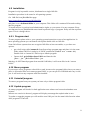
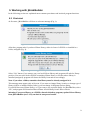
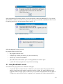
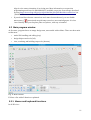
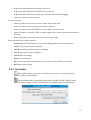
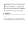
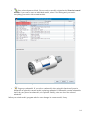
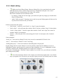
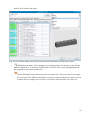
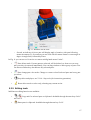
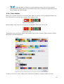
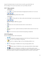
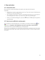
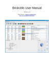
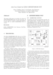
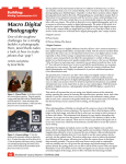
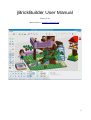
jBrickBuilder User Manual
Version 0.4.0
Mario Pascucci <[email protected]>
1
Index
1 Legalese............................................................................................................................................4
2 Thanks..............................................................................................................................................4
3 Release notes....................................................................................................................................4
3.1 What's new................................................................................................................................4
3.1.1 V 0.4.0...............................................................................................................................4
3.1.2 V 0.3.0...............................................................................................................................4
3.1.3 V 0.2.1...............................................................................................................................4
3.1.4 V 0.2.0...............................................................................................................................4
3.1.5 V 0.1.8...............................................................................................................................4
3.1.6 V 0.1.7...............................................................................................................................5
3.2 Limitations................................................................................................................................5
3.3 Known problems.......................................................................................................................5
3.3.1 Flexible parts saving.........................................................................................................5
3.3.2 Cross referencing blocks or chain referencing blocks......................................................5
4 Quick start........................................................................................................................................6
4.1 Thank you.................................................................................................................................6
4.2 What is jBrickBuilder...............................................................................................................6
4.3 What jBrickBuilder do..............................................................................................................6
4.4 What jBrickBuilder won't (never) do........................................................................................7
4.5 License and Warranty................................................................................................................7
4.6 Support......................................................................................................................................7
4.7 New releases.............................................................................................................................7
4.8 System requirements.................................................................................................................7
4.9 Installation................................................................................................................................8
4.9.1 Program start.....................................................................................................................8
4.10 Move program.........................................................................................................................8
4.11 Uninstall program...................................................................................................................8
4.12 Update program......................................................................................................................8
5 Working with jBrickBuilder.............................................................................................................9
5.1 First start...................................................................................................................................9
5.2 How jBrickBuilder works.......................................................................................................10
5.3 Main program window............................................................................................................11
5.3.1 Mouse and keyboard functions.......................................................................................11
5.3.2 File toolbar......................................................................................................................12
5.3.3 Sub-model toolbar...........................................................................................................13
5.3.4 Model editing..................................................................................................................15
5.3.5 Editing tools....................................................................................................................17
5.3.6 Color toolbar...................................................................................................................18
5.3.7 View controls..................................................................................................................19
5.3.8 3D options.......................................................................................................................19
5.3.9 Selection tools.................................................................................................................20
5.3.10 Step tools (for instruction generation)..........................................................................20
5.3.11 Design tools...................................................................................................................21
5.3.12 Rotation, grid and matrices...........................................................................................23
5.3.13 Catalogs menu...............................................................................................................23
5.3.14 Program menu...............................................................................................................24
5.4 Flexible parts editing..............................................................................................................25
6 Tips and notes.................................................................................................................................28
2
6.1 Connection hints.....................................................................................................................28
6.2 How to use unofficial or custom parts....................................................................................28
3
1 Legalese
LEGO®, LEGO Digital Designer, LEGO Technic are trademarks of the LEGO Group, based in
Billund, Denmark.
LEGO sets, parts and colors are exclusive property of LEGO group.
jBrickBuilder is NOT related, linked, sponsored or supported by LEGO Group.
2 Thanks
This program cannot be made without part library from LDraw project and his team and
contributors, that maintains a big database of 3D brick models.
Many thanks to the thousands of LEGO fans that maintains BrickLink sets and parts catalogs.
Special thanks go to all Romabrick people (http://www.romabrick.it) for support and suggestions
(and for pulling me out from the dark age)
3 Release notes
3.1 What's new
3.1.1 V 0.4.0
•
New step editing
•
New building step player
3.1.2 V 0.3.0
•
New flexible parts support (experimental)
3.1.3 V 0.2.1
•
Bugfix for Cut/Copy error.
3.1.4 V 0.2.0
•
New cut/copy/paste functions
•
Undo/Redo functions
•
Improved delete, duplicate and recolor functions
3.1.5 V 0.1.8
•
New rotation on connection function
•
Snap can be disabled
4
3.1.6 V 0.1.7
•
Antialiasing for better graphic aspect
•
Better align and rotation functions
•
Spatial indexing for fastest connection search on placing part
•
New part selection function by mouse dragging: drag a window on screen and all parts
completely inside of rectangle will be selected.
•
New selection functions: by part ID (design ID) and by color
•
Better connection strategy
jBrickBuilder is a Java™ application to build virtual models using LDraw part library. This is a
“beta” public release and must be considered highly unstable.
Features, functions, procedures and file formats may change without prior notice.
3.2 Limitations
•
Program does not checks for part collision: you can place a part “inside” another part,
program is unable to detect it. Is up to you to verify if part is placed correctly.
•
There isn't autosave (planned)
•
It is a beta version, so it is full of bugs and incomplete.
•
There is a connection database for “snapping” parts together, but it is incomplete
•
Some meta commands are partially or totally supported, but program leave it untouched in
source file.
3.3 Known problems
3.3.1 Flexible parts saving
Program can't save generated flexible parts automatically. Generated parts are added to the
submodel list and marked red. To save, select it for editing and use Save button.
3.3.2 Cross referencing blocks or chain referencing blocks
There is no easy way to avoid cross reference between blocks. If you create a submodel A, then a
submodel B that contains submodel A, then edit submodel A to include submodel B, program will
crash with a stack overflow.
Even if you put a complex control to avoid cross referencing blocks, you can use a chain reference
to trigger same problem: submodel A, including submodel B, including submodel C, including
submodel A, and so on.
Avoiding such problem is up to you.
5
4 Quick start
4.1 Thank you
I (the author) wish to thank you for using my program. It isn't perfect, and I know it need a lot of
improvements, but It is a complex piece of software, and I work on it in my free time.
This doesn't mean that program is worthless:
•
11000 lines of code (not counting blanks and comments)
•
54 Java classes, with over 800 methods
It was developed in over a year, using Eclipse (http://www.eclipse.org/).
Using a simplified COCOMOII model, develop this software will costs over $140.000
(http://sunset.usc.edu/csse/research/COCOMOII/cocomo_main.html).
4.2 What is jBrickBuilder
It is a simple CAD for virtual LEGO® models, using LDraw free part library.
It is an open source licensed software, developed in Java.
So, you don't need to pay any license at all, or you don't have to pay anything to anyone to use
jBrickBuilder.
jBrickBuilder works on any operating system and platform where Java release 6 is available.
It uses 3D part library from LDraw project (http://www.ldraw.org/).
JBrickBuilder is an independent program, deeply different from any other brick-related
CAD: so, please, forget LDD, MLCad, LeoCad, SR3D, and any other CAD.
If you want to use JBrickBuilder do not start from thinking things like “it is an LDD clone”,
or “it's the same as XYZCAD”. You MUST read manual to learn how to better use
JBrickBuilder.
4.3 What jBrickBuilder do
•
Can read both .LDR and .MPD file formats (with some derived file formats: L3B, LCD, ...)
•
You can edit models and sub-model, without exiting from program, switching from a
submodel to another
•
You can choose parts and colors from official LDraw library, without any limitations.
•
Works in 3D with OpenGL, even with entry-level video cards
•
To place part it works like official LEGO® CAD Digital Designer™: it use a database for
part connections, when you move part near other bricks it will “snap” to the nearest
connection.
•
If part isn't in connection database, it tries to “autodetect” connections
•
If parts isn't in connection database and “autodetect” fails, you can place parts using some
helper functions, a placing grid with rotation and snap to position.
•
Can save both .LDR and .MPD formats
6
•
Works both with zipped parts library or with your local part library in a folder.
•
Complete user manual (PDF, english)
•
Works on any platform with Java Runtime Environment release 6 or newer. On Linux
platforms it works fine with OpenJDK.
4.4 What jBrickBuilder won't (never) do
•
jBrickBuilder don't use 3D model from LEGO Digital Designer: parts are copyrighted and
using it violates lot of laws.
•
jBrickBuilder will never use any data from LEGO Digital Designer, nor any other data from
similar programs: it only uses LDraw official part library
So, no features that needs these functions will (never) added to jBrickBuilder.
4.5 License and Warranty
jBrickBuilder is a free and Open Source software, release under the terms of GNU General Public
License version 3 or later at your option.
So, you don't need to pay for any license at all, and you don't have to pay anything to anyone to use
jBrickBuilder.
jBrickBuilder comes with no warranty of any kind. You can use the program “as is”, and if
program don't match your expectations, don't use it.
4.6 Support
To obtain support about program, you can contact me with my e-mail, listed at the start of this
document, or you can go to the program website that you can find in the About dialog.
Please note that jBrickBuilder was created for my personal use, and giving support to user isn't my
work. Question that are answered in documentation will be ignored.
4.7 New releases
New versions and updates are released when ready. There is no planning. Please refer to program
website that you can find in About dialog.
There are some planned features, but there is no timeline for releases.
4.8 System requirements
jBrickBuilder will require nothing special to works. Every computer sold from 2009 will works
fine. Minimum requirement are:
•
100MB total disk space (program, database, indexes, LDraw part libraries)
•
1 GB RAM
•
OpenGL capable video card with minimal 3D acceleration (any video card sold from 2009)
•
monitor with 1024x768 resolution
•
Java Runtime Environment 6 o later (works fine with OpenJDK)
7
4.9 Installation
Program is only in portable version, distributed as a single JAR file.
Installation procedure is the same for all operating systems.
Get JAR file from jBrickBuilder page:
https://sourceforge.net/projects/jbrickbuilder/
and place it on a dedicated folder in your computer. This folder will contains all files and working
data for program.
To install and use it you don't need administrative rights, so you can use it in any computer. Every
user that need to use jBrickBuilder must install a personal copy of program. Every user has a private
space. This is a design choice.
4.9.1 Program start
To start program please refer to your operating system instruction to start a Java application. In
most operating systems you can launch with a plain double-click on JAR file.
Some Unix/Linux systems does not recognize JAR files as Java executable, so you have two
options:
•
get a shell script called runme.sh from Sourceforge program page and place it in the same
folder where JAR file is, and give it “RUN” permission (chmod a+x runme.sh).
Double click on “runme.sh” shell script to launch program.
•
Open a shell, go in folder where JAR is and launch with:
java -jar jBrickBuilder.jar
Warning: do NOT launch program from outside JAR folder, it will create files in the “current
folder”.
4.10 Move program
If you want to move program to other disk or path, just move the program folder where you want to
place it. All needed files are in same program folder, so you can put in a USB disk and carry it with
you. It will work on any computer with Java installed.
4.11 Uninstall program
To remove program from your system you have only to delete program folder.
4.12 Update program
At startup program will checks for both application new releases and connection database new
releases.
When a new version is detected, program will display a message that explain what is new.
To update or upgrade program you will need the new JAR: put it in the same folder/location where
older program is. That's all.
8
5 Working with jBrickBuilder
In the following section are explained most common procedures and involved program functions.
5.1 First start
At first start, jBrickBuilder will show a welcome message (Fig. 1).
Fig. 1: First start
After that, program asks if you have LDraw library, either in form of a ZIP file or installed in a
folder, unzipped (Fig. 2).
Fig. 2: Program asking for library
Select “Yes” button if you want to use your local LDraw library, and program will asks for library
position. You can select both a ZIP file containing LDraw library or a folder where library is
installed (unzipped): program will detect the library form and act accordingly.
Note: if you select a folder, remember that library must be already unzipped in it.
This message must appear only at first run. If you want to change library location or change type of
library (zipfile or installed library folder), you can change in Program Options dialog.
If you don't have any LDraw library, or if you want to use a private library for jBrickBuilder, select
“No”, and program will download latest LDraw official library from LDraw website.
Warning: if you use a library as a ZIP file, shared with other program, update LDraw library
from jBrickBuilder (see 5.3.13) can lead to unexpected results.
9
Fig. 3: Download connections database
After program acquired LDraw library, next will download connection database (Fig. 3), a special
database that contains how bricks are “connected” each other, and builds a database to allow search
for part by part id or by full text search (Fig. 4 and Fig. 5).
Fig. 4: Database building
Fig. 5: Parts summary
After that program is ready to work.
In program folder you will find:
•
the program JAR file itself
•
complete.zip: LDraw part library (if you downloaded it)
•
ldrconn.zip: connections database
•
jbb.h2.db and a folder named “jbb”: working database for LDraw parts
•
a .prefs file where program saves its preferences/settings
5.2 How jBrickBuilder works
To build a model, program uses two different strategies:
•
if a part has known connections (is in database or can be auto-detected) program will use
them to “snap” part to the nearest connection on line of sight. For some connection type,
program is able to “align” part to connection, so if you have a brick placed with an angle of
15 degree (to say), when a brick is “snapping” on it, program will rotate automatically to
10
align it to the same orientation of receiving part. More information on connection
programming model used in jBrickBuilder is available on project SourceForge download
section (https://sourceforge.net/projects/jbrickbuilder/files/jbrickbuilder/connections/) in
“jBrickBuilder connection model – developer manual”.
•
If part doesn't have known connections and cannot be autodetected, you can disable
autoconnect (
button) and use grid/snap controls to move and align part. It is less
“user-friendly” but you can place parts everywhere, with any orientation.
5.3 Main program window
At first start, program shows an empty design area, surrounded with toolbars. There are three main
toolbar area:
•
model file handling and editing (top)
•
design helpers and tools (left)
•
view, rendering and building steps tools (bottom)
Fig. 6: Main window
Follows a list with all functions explained.
5.3.1 Mouse and keyboard functions
In all 3D view:
11
•
drag mouse with right button pressed: rotate view
•
drag mouse with right button and SHIFT key: pan view
•
drag mouse with left button pressed: parts selection with window dragging
•
turn mouse wheel: zoom in and out.
In editor window:
•
mouse left button click on a part: select a part, deselect all other
•
mouse left button click on empty area: deselect all parts
•
mouse left button click with SHIFT on a part: add to selected part list
•
mouse left button click with CTRL on a part: toggle select (select if deselected, deselect if
selected)
•
mouse right button click on a part: center view on part origin
Keyboard functions in editor window:
•
Arrow keys (with part/block on cursor when adding part/block): rotate part/block
•
Ctrl-C copy selected parts to clipboard
•
Ctrl-X cut and copy selected parts to clipboard
•
Ctrl-V paste parts saved on clipboard
•
Ctrl-Z undo last change
•
Ctrl-Y revert last undo
•
ESC cancels any function and release part on cursor without adding it to model.
•
Del deletes selected parts.
5.3.2 File toolbar
•
New model. Starts a new project, cleaning current project. If current project is
modified, asks for confirmation.
•
Open existing model. Opens and load in editor a model in LDR or MPD format,
replacing current model, if any. If current project is modified, asks for confirmation.
Fig. 7: Set model information
12
•
Set model information. Opens a dialog (Fig. 7) to enter model description and author.
Author field is filled with default defined in Program Options (see 5.3.14). License notice is
defined in same dialog, and here you choose if include a license notice or not in your model.
•
Save current model. If it is first save, it shows a save dialog to ask for file name and
folder. Save model in LDR format. Warning: does not save submodels and flexible parts
generated by program: user must checks that submodels are properly saved and named.
•
Save current model as. Change name and folder for current model. Warning: if model
contains submodels please check that submodels are in the same folder.
•
Export current model and submodels in MPD format. Includes all submodel and
custom parts in model. Warning: does not include parts in official or unofficial library (both
zipped or installed).
5.3.3 Sub-model toolbar
You can load a submodel to include in a model, or you can switch editing from model to another or
a submodel without reload program.
•
Load a model as submodel. After loading you can place submodel as normal part. It is
included in submodels list (see below)
•
Select a block/submodel for insert or editing. Will show a dialog (Fig. 8) where you
can see all submodel loaded and select one for insert in current model (button “Insert”) or to
switch model editing (button “Edit”). Program generated parts (as flexible parts, see 5.4) are
marked in red if not saved on disk by user.
13
•
Save selected parts as block. Do not touch or modify original model. Part isn't saved
on disk: if you want to save as individual model, select it for editing and you can do
everything you can do with normal models.
Fig. 8: Sub-model dialog
•
Ungroup a submodel. If you select a submodel, after using this function all parts in
submodel are placed in current model, replacing submodel. If submodel contains submodels
itself, they are placed as submodel, not exploded. Briefly, raise one level the selected
submodel.
When you switch model, program asks for save changes in current model, if any.
14
5.3.4 Model editing
•
Add a part from LDraw library. Shows a dialog (Fig. 10) to search and select a part
from library. Part can be rotated using arrow keys on keyboard, and part color can be
changed on the fly, selecting new color from color toolbar.
Part can be searched with two different mode:
◦ by category. Using list in lower right, you can browse parts by category, a classification
done by LDraw team.
◦ with a “full text search”. Entering some words in top text field program will shows a list
of parts selected from words you entered.
Full text search uses this syntax:
•
“brick slope” - search for word “brick” or “slope” in part description
•
“brick -slope” - select all parts that contains “brick” and not contains “slope” in description
•
“+brick +slope -duplo” - search for parts that contains “brick” and “slope” but must not
contains “duplo” in description.
•
“brick*” - select all parts with word starting with “brick” in description, like “bricked”,
“bricks”, ...
Some examples:
“brick 2 4” - first result is a Duplo™ brick 2x4, second is a standard LEGO brick 2x 4.
“axle 7” - first result is a Technic™ axle 7 stud long.
“minifig hair pony*” - first seven results are all minifig hair with ponytail.
In part listing, there are a new function to see if a part has connections in database: if a row is
highlighted in green, part has specific connection data in database. If a row is highlighted in light
cyan part connection are autodetected and was verified for correctness.
If you select a flexible part, “Flex Part” button enables: if you click on it, you will enter in flexible
part editing mode (TBD)
•
List of last used parts. Shows a list of parts you used from program start.. It is cleared
only on program close. From here you can pick a part you know you already used in current
Fig. 9: Last used part
15
build. List is limited to 80 parts.
Fig. 10: Part search dialog. Part in green and cyan has connection working and verified.
•
Duplicate part mode. Cursor changes to a red square and you can select a part already
placed to duplicate it. If you have “Repeat brick” function active, after placing duplicated
part program let you select another one.
•
Rotate brick/part using connection point as rotation axis. This tool works in two steps:
◦ first you must select what part and which connection point in that part you want to use as
a rotation axis: an orange cross will show you what is selected when you click on it.
16
Fig. 11: Rotation tool at work
◦ Second, an indicator in lower part will display angle of rotation, with part following
mouse movement. To fix rotation you can click with left mouse button or enter angle in
degree in angle field, followed by Enter.
In Fig. 11 you can see tool in action to rotate a minifig hand around “wrist”.
•
Start delete mode. If some parts are selected, will be deleted, on from now on every
part you select is removed immediately. You can drag window to delete group of parts. You
can also use Delete key, that deletes only selected parts.
•
Start change part color mode. Change to current color all selected parts and every part
you select.
•
Step editor and player, see 5.3.10 - Step tools (for instruction generation).
•
Reset editor mode to select only, releasing any current action.
5.3.5 Editing tools
Well-known editing function are available:
•
•
Copy and Cut selected parts to clipboard. Available through shortcut keys Ctrl-C
and Ctrl-X.
Paste parts in clipboard. Available through shortcut key Ctrl-V.
17
•
Undo and Redo. Actions are recorded until user starts a new model or load a
model from disk. Undo and Redo are available after a save. Available through shortcut keys
Ctrl-Z (Undo) and Ctrl-Y (Redo).
5.3.6 Color toolbar
Allow you to choose color for next inserted parts. When you select a color, program will add to the
list of last used, so you have up to sixteen colors ready for use.
Fig. 12: Color toolbar
When toolbar is full, next color you choose will substitute least used color in list.
Fig. 13: A transparent color
selected (Tr. red)
Transparent colors will shows with a white faded point at center of button. When selected, brick in
main button become transparent.
Fig. 14: Color palette
To select a new color, click on button with white brick. It shows a complete palette of colors.
18
A green check marks current color, and colors are sorted by type and tint (Fig. 14).
You can change color of part at any moment, even if you already selected it.
5.3.7 View controls
Rotate model. Rotates left/right/up/down model view. You can use
•
mouse right button drag. Rotation has no limits.
Pan model view. Move model up/down/left/right. You can use mouse with
•
right button drag and SHIFT key together.
•
•
•
Zoom view. You can also use mouse wheel to zoom in and out.
Reset view. View is pointed towards 0,0,0 and all rotations removed. Zoom is not
modified.
Reset zoom. Zoom is restored. Rotation and panning is maintained.
5.3.8 3D options
These are all toggle buttons, with on/off position.
•
•
Orthogonal or perspective projection. Switch between 3D projections without
change other view controls (default is orthogonal).
Turn off or on lighting. If light is off, uses flat lighting (default is on).
•
Fill polygons. If disabled, shows only part edges (default is fill).
•
Display edges. If disabled do not shows part edges (default is display edges).
•
Normal or low detail parts. If available, use a low details model for some
elements. It can speed up rendering on old computers (default is standard details). Warning:
this function requires a complete re-rendering and needs few seconds to redraw model.
19
5.3.9 Selection tools
Program can select parts form current model by color or by part ID (or LDraw ID). Select a part
with desired design ID or color and click on:
•
to select all parts with same design ID/LDraw ID.
•
To select all parts with same color.
5.3.10 Step tools (for instruction generation)
During normal build you can enable stepping, and assign elements to a step. Step are numbered for
easy identification, and can be added at any moment during building.
In the lower part you can see a box with “current step” displayed. Some buttons helps to navigate
through steps:
•
•
go to previous step
go to next step. If next step don't exists, creates a new step. If current step is empty, do
nothing.
•
Go to first step in model
•
go to last step in model.
You can start use step at any moment during design: if you already added lots of elements, all
elements will add to first step.
Every element you add or modify will add to current step. You can change current step in any
moment during editing.
To review and edit steps for building process, you can use a step editor, activated by
button.
In editing window, model will display in “build sequence” mode, where:
•
elements in current step are highlighted with bright red edges
•
elements in next steps are dimmed and transparent.
•
elements in previous steps are rendered in usual way
“dimmed” elements can be selected and moved to other steps, or hidden to allow you to select more
internal elements in model.
20
Fig. 15: Step editor
In Fig. 15 you can see the Step Editor in action: windscreen and two other part in rear fuselage are
highlighted in red (these are parts for building step number 20), a dimmed wing is selected (boxed
in green).
In the lower toolbar you have some buttons:
•
move selected parts to previous build step. If it is already the first step, do nothing
•
move selected parts to current build step
•
move selected parts to next building step. If it is last step, creates a new one after last
step.
It can happens that you creates empty steps (i.e. moving all parts to another step): when you save
model or export it in MPD format, empty steps are ignored and doesn't appears in file.
5.3.11 Design tools
Program uses a plane and a cursor to mark the point where next part is placed, using part origin.
The plane can be moved, rotated and oriented according to generic direction or aligned to already
placed part.
If you use autoconnect, plane is only an helper, but if you don't use autoconnect plane is where part
21
is placed, so you need to move and rotate it precisely.
Remember that LDraw coordinate system is a bit different from other applications:
•
X axis if from left to right (right is positive, black arrow on editor)
•
Y axis is from top to bottom (“up” is negative, blue arrow on editor)
•
Z axis is from you to screen (“near” is negative, “far” is positive, green arrow on editor)
To move plane:
•
move grid plane up and down (along Y axis).
•
Move grid plane left or right (along X axis).
•
Move grid plane near or far (along Z axis).
Movement amount is determined by snap size (see below).
To align grid plane:
•
XZ align grid plane to plane XZ using current origin
•
XY align grid plane to plane XY (screen plane)
•
YZ align grid plane to plane YZ (perpendicular to screen)
•
align grid plane to the same matrix of selected part. It is really useful to build with
SNOT or winged models: place first part with needed angle, and align grid to part placed:
next parts will automatically oriented with same rotation matrix.
•
Reset grid plane to defaults. Do not change snap or grid size, only reset rotation matrix.
•
Reset pointer/cursor rotation to default. Do not touch grid, grid orientation or snap.
•
Grid display on or off. Toggle only display, grid is always used for part moving and
placing.
•
Snapping on or off (default on). If on, cursor will move only on grid vertices of size
“snap” LDU. Grid is in three dimension so X, Y, Z will always be multiple of snap size.
•
•
Axis display on or off. Axis are always on absolute origin coordinates (0,0,0)
set snap size (in LDU). Default is 4 LDU. Snap is in 3D, so you can think as a grid of
cubes where sides are the size of snap. Cursor always move only on snap vertices. Minimum
snap size is 0.1 LDU.
•
Set grid size. Grid size is totally unrelated with snap size, and it is only a visual guide.
•
Set rotation step (degree). When you use arrow keys to rotate part/block, amount of
22
rotation is defined here. Default is 90 degree.
•
Enable/disable part autoconnect (toggle button). This is a powerful function: if part is
in connections database, program will “snap” to the nearest valid connection when you
move in editor. If you disable this function, you must use “placing helper” (see below) to
place a part where you want.
•
Repeat insert of last part (toggle button). After you place a part, this function get
another part (same part with same color and same orientation) on your cursor. If you disable
it, after placing a part you must select a new one every time.
•
Hide selected parts. Hidden parts isn't used for autoconnect, so if you have problem
connecting part you can hide “interfering” part. It is an helper to edit complex models. You
can hide as many part as you want. Blocks are hidden as a single part.
•
•
Show all hidden parts.
Take a screenshot of what is on editor window. Save to a PNG image format, asking
where to save.
5.3.12 Rotation, grid and matrices
JBrickBuilder uses two set of data for orientation and position of parts during building:
•
grid matrix
•
pointer/cursor matrix
Grid matrix defines position and orientation for parts in whole design space. Pointer matrix defines
local rotation for placing parts. Parts are placed using grid matrix multiplied to pointer matrix.
So, if you want to build using SNOT technique, first you can define orientation using
or one
of XY, XZ, YZ buttons to align main grid to the desired direction, next, you can rotate parts using
grid as a base plane. You can reset pointer, grid or both rotation using related buttons.
It is a bit complex, but when you grasp the base idea it is really useful to build complex models.
5.3.13 Catalogs menu
When LDraw team releases a new catalog you can update it using this menu.
•
Download LDraw library – download and update official library from LDraw web site.
This functions works only for zipped library, if you use local installed library (unzipped),
LDraw library update is up to you. Warning: if you use a library as a ZIP file, shared
with other program, update from this menu can lead to unexpected results. You can
broke other programs using same library file or you can get an error if program
cannot write/overwrite old library file.
•
Download connections database – When a new connections database is released, you can
use this function to download and use it.
•
Refresh parts database – Both if you have a local installed LDraw library or use the zipped
23
one, when you update library this function updates part list and search tables with
new/modified parts, otherwise you can't see new parts.
5.3.14 Program menu
In this menu you can find an exit function (same as closing program main window). If current
model is modified program will ask you a confirm.
The about dialog shows you some information about program and author.
Fig. 16: Options dialog
In Option dialog you can set some program functions like LDraw library folder:
•
Use extended color palette: if enabled, in color selection dialog you will find all colors,
else program shows you only currently in production colors.
•
Author name and e-mail: fill with your name, nick and other information. This text will be
inserted in models in “Author:” line.
•
Use installed LDraw library, instead of zipped: if you have ZIP and local installed library,
this option lets you choose what library use. If checked use installed (folder) library. If you
want to change this option make sure you have the right path to file or folder in next options.
•
Grid size/Snap size in LDU: last values used in program. If you change in editor, program
will retain new values. “0” means use defaults (4 LDU for snap and 20 LDU for grid size).
•
Path to library folder/zip file: if you move/change library position you can set new
position here. Warning: these values are critical for program. If you changes one of this
you must restart program and use “Update parts database” (see 5.3.13) to view changes in
library.
•
License text for new models: if you chose to put a license notice in a new model, this text
go in the LDraw “!LICENSE” meta-command.
•
Use low details parts: it forces program to use low-detail version of some primitives, to
24
lower the program requirements for graphics and memory. Save status of low-detail button
(see 5.3.8).
•
Use perspective view: save setting for perspective/orthogonal projection view (see 5.3.8).
•
Use antialias (req. restart): enables graphic card antialias for better graphic result.
Requires program restart. Requires a bit more GPU power.
5.4 Flexible parts editing
Starting from release 0.3.0, jBrickBuilder can generate flexible parts with custom path and bending.
Warning: support is experimental and in development, so specifications and functions can
change in next releases.
There are no special buttons or menu functions: when you select a part that is “flexible” and listed
in supported parts, in the part selection dialog you will see the “Flex Part” button enables.
If you click on it, you will enter in flexible parts editing mode, that is a three step procedure:
Fig. 17: Head of flexible axle
1. place flexible part “head” (Fig. 17). Heads of flexible parts have connection enabled and
checked, so you can “snap” it on other parts, when connection is “valid”. A green tool will
show you where the flexible “start” is oriented.
Fig. 18: Placing tail
2. place flexible part “tail”. As for heads, tail have connection points. An “elastic band” goes
from head to tail position (Fig. 18), and a green tool shows the direction of flexible part final
part, as a preview for final part. If band is green, your path length is less than real part
length. If you put tail too far from head, band become red, but it is only a visual warning,
nothing more: program will not refuse to create final part
25
3. place optional constraint points. If your part must go through specific point, or hole in
another brick, you can place a point in three-dimensional space that is a fixed point where
the final path must go through. A button in lower part allow you to delete last constraint
added, if you place it in wrong position.
Fig. 19: Adding a constraint
A green arrow (Fig. 19) show the direction which path crosses the constraint point.
Fig. 20: Wrong constraint point orientation
If you place a constraint point with wrong orientation (Fig. 20), you will get weird results.
You can “snap” a constraint point to a connection point: a peg hole, an axle hole, a clip, all are point
where a constraint point can “snap”, allows to simulate real world models, where a pneumatic tube
can go through a Technic™ brick peg hole or a flexible 3mm-hose can snap into a clip-type
connection.
26
Fig. 21: One constraint point placed
If your constraint point is well placed, or when you see desired path, you can click on “Accept”
button in lower part.
Fig. 22: Generated flexible axle
Generated parts are normal parts, listed as “custom submodels”. Can be deleted, moved, copied, but
you cannot change original path: to do that you need to place a new flexible part.
For more information on flexible part programming model used by jBrickBuilder, you can refer to
“jBrickBuilder flexible parts model – developer manual” available in jBrickBuilder downloads
section (https://sourceforge.net/projects/jbrickbuilder/files/jbrickbuilder/flexparts/).
27
6 Tips and notes
6.1 Connection hints
Part connection is a really useful feature, but requires some time and a bit of practice.
Some hints:
•
program tries to connect to parts nearest to user's eye. If you can't connect to desired part, try
to rotate view to move part nearest to you.
•
Also, program tries the nearest connection to line that goes from user eye to cursor (the red
cross). If program can't connect, try to rotate view to drive away interfering part.
•
At last, you can hide interfering part or parts with
connection logic.
function. Hidden parts are ignored in
6.2 How to use unofficial or custom parts
To use unofficial or custom designed parts, you can add to your model as a block (using
and
functions). Remember that included parts must be in same folder of main LDR file.
Custom parts will be exported in MPD file as a normal sub-model.
This way you can include parts not in official library and distribute a model that can be viewed and
edited with any other LDraw editor. When someone loads your model, it will have all parts needed
to view/edit.
28