1
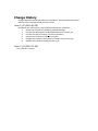
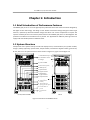
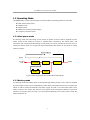
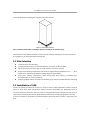
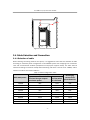
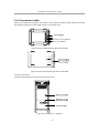
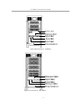
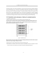
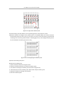
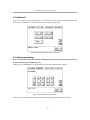
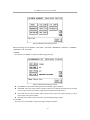
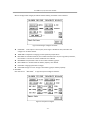
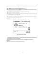
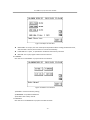
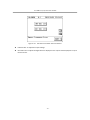
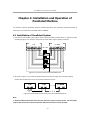
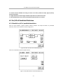
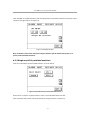
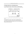
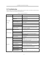
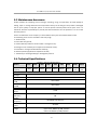
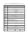
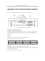
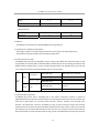
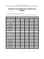
CATALOG
Chapter 1: Introduction ....................................................................................................................... 1 1.1 Brief Introduction of Performance Features ...................................................................... 1 1.2 System Structure.................................................................................................................... 1 1.3 Operating Mode...................................................................................................................... 3 1.4 Functions and Characteristics............................................................................................... 5 Chapter 2: Installation Instruction ..................................................................................................... 7 2.1 Unloading and Unpacking ..................................................................................................... 7 2.2 Site Selection .......................................................................................................................... 8 2.3 Installation of UPS ................................................................................................................. 8 2.4 Cable Selection and Connection .......................................................................................... 9 2.5 Battery Connection .............................................................................................................. 13 Chapter 3:Operation ........................................................................................................................ 17 3.1 Introduction of Operation Interface .................................................................................. 17 3.2 Operation for Power on of Single Machine (10-60KVA for example)................... 18 3.3 Operation for Power off ...................................................................................................... 26 3.4 Operation for Emergency Power off .................................................................................. 27 3.5 Operation for Maintenance Bypass.................................................................................... 28 3.6 Enquiry Operation ................................................................................................................ 29 3.7 Operations for User Configuration..................................................................................... 36 Chapter 4: Installation and Operation of Paralleled Machine ...................................................... 49 4.1 Installation of Paralleled System ....................................................................................... 49 4.2 On/Off of Paralleled Machines............................................................................................ 50 4.3 Enquire Operation of Paralleled System ........................................................................... 52 Chapter 5: UPS Repairing and Maintenance ................................................................................... 53 5.1 UPS Repairing and Maintenance ........................................................................................ 53 5.2 Troubleshooting ................................................................................................................... 55 5.3 Maintenance Assurance ...................................................................................................... 58 5.4 Technical Specifications ...................................................................................................... 58 Appendix 1: Lamp Signal Reference List ......................................................................................... 61 Appendix 2: Port of Communication Interface ............................................................................... 63 Appendix 3: Dial Switch Set of Module and Charger..................................................................... 66 PREFACE Thank you for using our products. Our company is engaged in developing and manufacturing products of uninterrupted power system which is a kind of power product with high quality and can meet various performance requirements. Note:
This manual contains instruction of mounting, application, and operation of UPS. It shall read this manual carefully before mounting the system and it is not allowed to take any operations on UPS before finishing reading all safety instruction and operation instruction. This manual contains significant information, please obey all warnings and operation instructions stated by the manual and machine, and the manual shall be kept well. Safety:
The uninterrupted power system must be grounded before operation. Battery shall be replaced by qualified maintenance personal. The battery is toxic waste according to laws, so wasted battery shall be recovered by its classification in accordance with requirement of environmental protection. Warning:
Selling of this product is only for partner who has general information on UPS products. It is necessary to know some other mounting requirements or measures to prevent accident. Any content of the manual shall not be modified without allowance of manufacturer and any offenders must be investigated. Our company reserves the right of final interpretation. Change History
Changes between document issues are cumulative. The latest document issue contains all the changes made in earlier issues. Issue V_02 (2014‐04‐10) Compared with V01 version, the modified contents are as follows: 1. Delete the contents of unpacking module package. 2. Increase the descriptions of 80‐120KVA based on Issue V_01. 3. Increase the way of setting +15 pieces of battery. 4. Increase the function of input dry contact. 5. Change the number of dial switch of module ID, 4 pin to5 pin. 6. Update some pictures based on Issue V_01. Issue V_01 (2012‐11‐30) This is the first release. 10-120KVA (3/3) UPS user manual
Chapter 1: Introduction
1.1 Brief Introduction of Performance Features
10‐120KVA (3/3) series is a kind of high‐frequency UPS with three‐inlet and three‐outlet designed by full digital control technology. The design of unit breaks conventional design thought of tower‐type machine, replaced by advanced modular design idea which can ensure compactness of layout and improve reliability of the unit. Electrical performance of 10‐120KVA (3/3) series is advantageous and protection of software and hardware of it is perfect. It is applicable for different power grid and can supply safe and reliable power for different loads. 1.2 System Structure
Components of the system mainly include: LCD display screen, communication port, power module, charger, battery (optional), input breaker, output breaker, maintenance bypass breaker, ground row, N row, and so on. Its system structure chart is shown in figure 1.1, figure 1.2 and figure 1.3. 1. communication port
2. LCD display screen
3. Charger
4. power module
5. SPD breaker(optional)
6. SPD(optional)
7. Input breaker
8. Bypass breaker
9. Maintenance
bypass breaker
10. Output breaker
11. Battery pack
12. Terminal block
of battery
13. Terminal block of
input,bypass and output
14. Terminal block of
ground
15. Terminal block
of N
Front(without baffle)
Back Figure 1.1 Structure of 10‐30KVA series -1-
10-120KVA (3/3) UPS user manual
1.Communication port
2. LCD display screen
3.Power module
4. Charger
5. SPD breaker(optional)
6. SPD(optional)
7. Input breaker
8.Output breaker
9. Maintenance bypass breaker
10. Bypass breaker
11. Terminal block of
input,bypass and output
12. Terminal block of battery
13. Terminal block of ground
14. Terminal block of N
Front(without baffle)
Figure 1.2 Structure of 40‐60KVA series Back 1.Communication port
2.LCD display screen
3.Power module
4.Charger
5.Charger(Optional)
6.SPD(Optional)
SPD Breaker Surge Protection Device
7.SPD breaker(Optional)
8.Output breaker
9.Maintenance bypass
breader
10.Bypass breaker
11.Input breaker
Front(without baffle)
Figure 1.3 Structure of 80‐120KVA series -2-
Back
10-120KVA (3/3) UPS user manual
1.3 Operating Mode
10‐120KVA (3/3) is a kind of online double‐conversion UPS, its operating modes are as follows: z Main power supply mode z Battery mode z Bypass mode z Maintenance mode (manual bypass) z Frequency converter mode 1.3.1 Main power mode
The working mode that alternating current power of rectifier circuit for UPS is supplied by main power, direct current power for inverter is supplied after corrected by PFC power factor, and continuous and uninterrupted alternating current power for load is provided by inverter circuit is called main power mode. The charger will start automatically after power on of inverter to supply power for battery. Figure 1.4 Working Process Chart under Main Power Mode 1.3.2 Battery mode
The working mode that battery power is boosted through battery booster circuit, and then supplied to load through inverter circuit is called battery mode. When main power fault occurs, the system will switch to battery mode automatically and power supply for load is not interrupted. When main power recoveries, the system will switch to main power mode automatically without any manual operation and power supply for load is not interrupted. Switching time of main power mode and battery mode is 0 ms. -3-
10-120KVA (3/3) UPS user manual
Maintenance bypass bypass
AC/DC rectification Main powe input
+
DC/DC boost DC/AC inverter Out put
-
BATTERY
Charger Figure 1.5 Working Process Chart under Battery Mode 1.3.3 Bypass mode
If fault, such as inverter circuit fault and inverter circuit overload, or switching to bypass mode by hand occurs, the UPS will switch the load from side of inverter to side of bypass and power supply for the load is not interrupted. Figure 1.6 Working Process Chart under Bypass Mode 1.3.4 Maintenance mode (manual bypass)
If it needs to maintain or repair the UPS, it can close the manual bypass switch to switch the UPS to the side of maintenance bypass and the power supply for load is not interrupted. In that case, the main power will not pass the internal components of machine but connect the input terminal and output terminal directly so that we can maintain or repair the UPS. -4-
10-120KVA (3/3) UPS user manual
Figure 1.7 Working Process Chart under Maintenance Bypass Mode 1.3.5 Frequency converter mode
UPS can be set to frequency converter mode which can provide stable output frequency of 50Hz or 60Hz. Input frequency range of main power is 40 Hz ~ 70 Hz. UPS will output the set output frequency and the bypass mode is ineffective under frequency transformer mode. When main power is abnormal, the system will switch to battery mode automatically and still output with the set output frequency. 1.4 Functions and Characteristics
z DSP full digital control technology; z Pure online double‐conversion framework, strong load capability; z Input power factor is as high as more than 0.99, low harmonic current, environmental protection, high‐efficient, and energy saving; z Wide input voltage range, 50/60 Hz power system self‐adoption suitable for all grid under any circumstance; z Support frequency modes of 50 Hz input / 60 Hz output and 60 Hz input / 50 Hz output which can meet special requirements of user; z Advanced “N+X” wireless parallel connection redundant technique, high parallel reliability and small circulation; z Parallel machines share the battery group which can save cell investment from user; z Digital charger with flexible charging parameter set and battery pieces selection; z Advanced battery intelligent management technology which can prolong working life of battery effectively; z Support cold start of battery and automatic start of normal power which can meet user’s application requirements; z Easily damaged components are completely isolated with air flue which can improve reliability of the system effectively; -5-
10-120KVA (3/3) UPS user manual
z Easily damaged components can be changed in module level, field replacement is fast and convenient and module cost is low; z Perfect hardware and software protection function (breaker, Fuse, hardware protection, and software protection), super self diagnosis, and rich historic record enquiry; z 5.7 inch LCD touch wide screen display, friendly human‐machine interface; z Many communication ports, including RS232, RS485, USB, dry contact card and SNMP smart card trough. -6-
10-120KVA (3/3) UPS user manual
Chapter 2: Installation Instruction
2.1 Unloading and Unpacking
User shall check the package to confirm it is undamaged after receiving the product; then open the package to check whether the equipment is undamaged, and please contact the carrier at once if it is damaged. 2.1.1 Open of cabinet package
1) Put the packing box vertically; Figure 2.1 Packing Box Placements 2) Open the top plate of packing box and then take out the foam; Figure 2.2 Unseal the Packing Box -7-
10-120KVA (3/3) UPS user manual
3) Unseal side plates of packing box and then take out the foams. Figure 2.3 Unsealed Cabinet Tips: It shall be careful when unsealing to prevent scratch for the machine body. Check whether the qualified certificate, instruction book, CD disk, and keys for front and back doors are complete or not after opening the packing box. 2.2 Site Selection
z
Placed location must be stable; z
Enough ventilation space must be left between all surfaces of UPS and walls; z
Be far away from hot source and corrosive materials, avoid the sunshine; z
Keep normal working temperature and elevation height (working temperature: 0℃ ~ 40℃, it needs to be applied by derating if elevation height exceeds 1500m); z
Keep clean working environment, avoid environment with moisture, flammable gas, flammable liquid, or corrosive material; z
Weight capability of floor to machine and battery group shall be considered before mounting. 2.3 Installation of UPS
Location of placing the UPS shall be proper in order to ensure safety application of UPS. It shall be placed in place with clean environment without moisture, flammable gas, flammable liquid or corrosive material and sunshine. User can put it on assigned location with assistant of human force or equipment and shall pay attention to spaces between UPS and surrounding things when mounting so that it is helpful for ventilation and heat dissipation. Minimum space is shown in figure 2.4 (unit: mm): -8-
10-120KVA (3/3) UPS user manual
Figure 2.4 Cabinet Placement Chart 2.4 Cable Selection and Connection
2.4.1 Selection of cable
When selecting connecting cable for the system, it is suggested to select the wire diameter of cable according to maximum power configuration of 10‐120KVA system and complying local connection rules and environmental condition (temperature and physical support media). The cable shall be selected according to maximum steady‐state alternating and direct currents of 10 ‐120KVA, and its selection conditions are listed in table 2.1: Table 2.1 Cable Configuration Table UPS rated power 10KVA 15KVA 20KVA 30KVA 40KVA 60KVA 80KVA 100KVA 120KVA Rated 380V input Input current when it is full load and charger outputs maximum power 24A 31A 39A 53A 78A 117A 156A 195A 234A -9-
Discharging Output current of 32 current when pieces batteries
it is full load 15A 28A 23A 41A 30A 55A 46A 83A 61A 110A 91A 165A 121A 220A 151A 275A 182A 330A 10-120KVA (3/3) UPS user manual
2.4.2 Connection of cable
Battery input (long‐term machine), main power input, bypass and output cable shall be connected with UPS according to the paths shown in Figure 2.5 and figure 2.6. Figure 2.5 Inlet and Outlet Wiring Channel of 10‐60K Figure 2.6 Inlet and Outlet Wiring Channel of 80‐120K Connection of cable is: 1) Open the distribution board to expose the copper rows. Figure 2.7 Front View of 10‐30KVA - 10 -
10-120KVA (3/3) UPS user manual
Figure 2.8 Front View of 40‐60KVA Figure 2.9 Front View of 80‐120KVA - 11 -
10-120KVA (3/3) UPS user manual
2) Phases shown in following figure are line terminals of main power input, bypass input, battery input and output cable after passing the inlet and outlet wiring channels. Figure 2.10 Distribution Wiring Diagram of 10‐30KVA series Figure 2.11 Distribution Wiring Diagram of 40‐60KVA series - 12 -
10-120KVA (3/3) UPS user manual
Figure 2.12 Distribution Wiring Diagram of 80‐120KVA series Tip: please tighten the input and output cables and wiring row. 3) Recover the distribution panel 2.5 Battery Connection
2.5.1 Battery connection of long-term machine
Battery group for this machine is positive and negative battery group framework, total number of battery can be selected from 30 to 40 (even number), and quantities of positive and negative batteries shall be the same. Battery connection chart is shown in figure 2.13: Figure 2.13 Battery Connection Chart - 13 -
10-120KVA (3/3) UPS user manual
As shown in figure 2.13, connect all batteries in series, and lead a N line from middle connection point of battery groups, so it shall be three lines together with positive and negative ends of battery group to connect with battery connecting terminals of UPS. Batteries between positive end of battery group and N line are called positive batteries, and batteries between negative end of battery group and N line are called negative batteries. User can select the capability and number of battery according to its demand. It must add a direct current breaker between battery group and UPS to play a role of current‐limiting protection and open and close the battery group when maintaining. 2.5.2 Installation and maintenance of battery for standard machine
1. Installation of battery pack: 1) Open the battery pack panel in front of cabinet to expose the battery pack. Tips: This series can maximum allow 4 groups of battery pack, each group of battery pack has 16 pieces of battery. According to customers needs, 2 groups of battery (32 pieces of battery) and 4 groups of battery (64 pieces of battery) are for option. Figure 2.14 Battery Pack Note: It needs to turn on the charger solely before installing the battery for the first time to inspect whether the output voltage of charger is normal. 2) Remove the set screws of battery pack and extract the battery pack. 3) Put batteries into battery pack as shown in Figure 2.15 (battery positive and negative terminals must be located on the right side of the battery pack when installing the batteries). - 14 -
10-120KVA (3/3) UPS user manual
Figure 2.15 Right View of Battery Pack 4) Put the battery pack with batteries to corresponding location and lock the set screws. 5) Measure whether the voltage of every battery pack is normal(192~208V), then measure whether the side lead terminal is short‐circuit ,if all of them is normal, connect the battery pack with UPS according to the connecting method shown in following figure 2.15, if the voltage of battery pack is 0V, check whether the battery fuse is disconnect. Figure 2.16 Connecting Diagram of Battery Pack 6) Recover the battery pack panel. Maintenance of battery pack: 1) Switch the UPS to maintenance bypass mode. 2) Remove the battery pack panel to expose the battery pack. 3) Cut off the connecting line of battery pack (as shown in Figure 2.16). 4) Take away the set screw of battery pack and then take away the battery pack. 5) Replace the battery according to the demand. 6) Recover the battery pack. - 15 -
10-120KVA (3/3) UPS user manual
The following safety notes shall be noted all the time when mounting and maintaining the batteries: 1). Electric shock may occur when mounting the batteries, high short‐circuit current may cause fire; 2). Voltage of battery groups can be 480Vdc which may cause death, so please obey safety attentions for voltage operation; 3). Only qualified personal can mount and maintain the batteries; 4). Wear protective eyewear to prevent accident caused by electric arc; 5). Take off ring, watch, necklace, bracelet, and other aglets; 6). Use tools with insulated hands; 7). It shall break down the breaker of battery when connecting lines between UPS and battery. It must ensure that the sequence and polarity of connection are correct after finished connection; 8). Please contact customer service department of our company if the user needs to change the number of used batteries during normal application. Please do not operate it solely. - 16 -
10-120KVA (3/3) UPS user manual
Chapter 3:Operation
This chapter describes all enquiries and setting operations of UPS taken by operator, including starting of UPS, power off of UPS, all enquiry operations, and parameter setting, etc. Tips: instruction manual must be read carefully before implementing the following operations to avoid personal injury or equipment damage caused by misoperation. 3.1 Introduction of Operation Interface
As shown in Figure 3.1, operation interface mainly contains: LED indicator light, 5.7 inch multifunctional LCD touch wide screen and operation button. Indicator light
Operation button TAB
FAULT
UP
BYPSS
DOWN
BATTERY
ENTER
NOMAL
CANCEL
EPO
COLD START
LCD wide screen
Cold start Figure 3.1 Monitoring Interface Definitions of icons on panel silk‐screen and LCD screen are listed in table 3.1: Table 3.1 Silk‐screen/Icon Illustration Monitoring panel Icon/Silk‐screen FAULT LED indicator light BYPASS BATTERY NOMAL Icons on LCD touch screen Meaning Warn Power supplied by bypass Power supplier by battery
Power supplied by main power Setting
Charger
Battery On/Off
Input parameter
- 17 -
10-120KVA (3/3) UPS user manual
Output parameter
Return to main interface
Return to previous menu
Page down Page up
History
Self‐test and mute off
Record enquiry
Operation buttons TAB UP DOWN ENTER CANCEL COLD START EPO Switch of touch/button‐control Cursor up
Cursor down Confirm Return to touch‐control from button‐control Cold start Emergency power off LCD screen supports two kinds of control modes, button control and touch control. 1. Button control Press button of “TAB” under any interface to switch to button control mode, the selected icon is displayed in reverse, move the cursor by pressing button of “UP” or “DOWN”, press “ENTER” to select the icon where cursor locates at, and press “CANCEL” to return to touch screen control mode. 2. Touch control Take operations by clicking corresponding icons on LCD screen. 3.2 Operation for Power on of Single Machine (10-60KVA
for example)
Note: It shall check whether all screws are fastened and all connections are correct or not before starting the machine. Input, output, and battery breakers shall be in off state. For long‐term machine, it shall set the charger parameters before starting, and battery pieces and groups shall be match with the battery group. (Our professional engineer would do the right setting for users at the first time) - 18 -
10-120KVA (3/3) UPS user manual
3.2.1 Start under main power mode
1. Start main power mode directly 1) Connect the main power Close the input and bypass breaker and UPS connect to the main power and bypass. The UPS screen starts to work and then LOGO interface occurs. Figure 3.2 Logo Interface It will be refreshed to main interface after 1s,and the bypass will start automatically. Figure 3.3 Main Interface Click the icon of battery to check whether the battery set is match with actual battery configuration (detail operation can be seen in 3.7.9). 2) Start UPS Click icon of On/Off in main interface to pop the interface of On/Off. If it is the first time to start the UPS, user needs to enter the UPS on password, which getting from customer service. After this time, no password is needed to start the UPS. - 19 -
10-120KVA (3/3) UPS user manual
Figure 3.4 UPS ON password Click icon of “TO INV” and then UPS starts to power on under main power. Figure 3.5 On/Off Interface Process of starting UPS under main power mode will be finished after a time. The charger starts to power on automatically after the power module is started, and the starting of charger module is finished after a time. 3) Close battery and output breakers Close the battery break (long‐term machine) and output breaker after starting of UPS under main power is finished, and then the UPS start normal operation. Energy flow after it is started under main power mode is shown in Figure 3.6: - 20 -
10-120KVA (3/3) UPS user manual
Figure 3.6 Operations under Main Power 2. Switch from bypass mode to main power mode If the UPS is working under bypass mode, click the On/Off icon in main interface to pop the On/Off interface. Figure 3.7 On/Off Interface Click icon of “TO INV”, the UPS will begin to start the main power mode, and starting under main power mode will be finished after a time. 3.2.2 Starting under battery mode
If main power is fault, UPS can be turned on by battery mode directly. 1. Close battery breaker, input breaker and bypass breaker and connect the battery. 2. Press button of “COLD START” in control panel to turn on the LCD screen. LCD screen displays main interface. - 21 -
10-120KVA (3/3) UPS user manual
3. Press “ENTER” for 2s to build working power for power module, and then the fan of module starts to rotate. Click the battery icon to check whether the battery set is the same with actual battery configuration (Detailed operation is shown in 3.6.3 and 3.6.4). Figure 3.8 Main Interface 4. Click On/Off icon in main interface to pop the On/Off interface. Click icon of “INV ON”, and the starting under battery mode will be finished after a time. Figure 3.9 On/Off Interface 5. Close output breaker, and then the UPS output is normal and starting by battery is finished. Its energy flow is shown in figure 3.10: - 22 -
10-120KVA (3/3) UPS user manual
Figure 3.10 Battery Mode 3.2.3 Starting under bypass mode
It can switch to bypass mode directly under main power mode or under the case that main power is available but the UPS has not been started yet. 1. Start the bypass mode from standby mode (main power is available but the UPS has not been started yet). The UPS has not been started currently, and display of its main interface is shown in Figure 3.11: Click the battery icon to check whether the battery set is the same with actual battery configuration. Figure 3.11 Main Interface - 23 -
10-120KVA (3/3) UPS user manual
1) Click On/Off icon in main interface to pop the On/Off interface. Figure 3.12 On/Off Interface 2) Click icon of “BYP ON”, UPS will enter the bypass mode, and the bypass mode is started. The charger will start automatically after a time. 3) Close battery breaker (long‐term machine) and output breaker, and the bypass starts to output normally. Its energy flow chart is shown in figure 3.13: Figure 3.13 Bypass Mode 2. Switch to bypass from main power mode The UPS is working under main power mode currently, click icon of On/Off in main interface to pop the On/Off interface. - 24 -
10-120KVA (3/3) UPS user manual
Figure 3.14 On/Off Interface Click icon of “TO BYP”, and then the system will enter into bypass mode. 3.2.4 Start charger
1. Charger will start automatically to charge the battery when UPS is started under main power mode or bypass mode. 2. If the charger is off and needs to be restarted, when the UPS is in main power mode or bypass mode, it can click the On/Off icon in main interface to pop the On/Off interface, click icon of “CHG ON” below the “CHG ON/OFF”, and then the charger will be started. 3. Click the icon of charger in main interface to check the working state of charger. Figure 3.15 On/Off Interface of Charger 3.2.5 Starting by manual self-test
In order to ensure the battery state of UPS and prolong working life of battery, it needs to charge and release electricity of the battery periodically to ensure that the battery can supply power for UPS - 25 -
10-120KVA (3/3) UPS user manual
normally when main power fails suddenly. Click icon of self‐test and mute off in main screen, the popped interfaces include “TEST 10S”, “TEST 10M”, “TEST LOW”, “CLR TEST”, and “MUTE”. Click one of the first three options to select the self‐test time. Select different self‐test times according to the time of actual test period. Figure 3.16 Self‐test and Mute off Interface 3.2.6 Starting under ECO mode
If the main power is normal and battery is connected, when the bypass voltage qualified the need of ECO mode, click icon of “TO ECO”, after a while, system operating under ECO mode. 3.3 Operation for Power off
3.3.1 Power off under line mode
The UPS is working under main power mode currently. Click icon of On/Off in main interface to pop the On/Off interface. Click icon of “SHUT” to shut down the UPS, and the charger will be off automatically at the same time. Figure 3.17 Interface of Power off under Main Power - 26 -
10-120KVA (3/3) UPS user manual
3.3.2 Power off under battery mode
The UPS is working under battery mode currently. Click icon of On/Off in main interface to pop the On/Off interface. Click icon of “SHUT” to shut down the UPS. 3.3.3 Power off under bypass mode
The UPS is working under bypass mode currently. Click icon of On/Off in main interface to pop the On/Off interface. Click icon of “BYP OFF” to shut down the UPS, and the charger will be off automatically at the same time. 3.3.4 Power off the charger
1. The charger will be off automatically if the machine is powered off under main power mode or bypass mode. 2. Power off the charger when the machine is working under main power mode or bypass mode: 1) Click icon of On/Off in main interface to pop the On/Off interface. Figure 3.18 Power Off Interface 2) Click icon of “CHG OFF” below “CHG ON/OFF” to power off the charger. 3.4 Operation for Emergency Power off
Emergency power off (EPO) switch is used to power off the UPS under emergency situation (such as fire, flood, etc.). Press button of EPO in monitoring panel, the UPS will cut off output at once and cut off the power in several seconds. If it needs to power on the machine again, it shall take the power on operation after cutting off the power of UPS for 30s. - 27 -
10-120KVA (3/3) UPS user manual
3.5 Operation for Maintenance Bypass
3.5.1 Start of maintenance bypass
1. Select option of On/Off in LCD main interface, select icon of “TO BYP” in On/Off interface, and confirm the UPS is working under bypass mode in LCD screen. Figure 3.19 Bypass Mode 2. Open the cover of maintenance bypass breaker, close the maintenance bypass breaker, cut off the output and battery breakers, and then the UPS enters into maintenance bypass mode. Its energy flow is shown in figure 3.20, and then cut off the input breakers and bypass breaker. Figure 3.20 Maintenance Bypass Mode - 28 -
10-120KVA (3/3) UPS user manual
3.5.2 Exit of maintenance bypass mode
1. Close the input breaker and bypass breaker, the power module builds working power and switches to bypass mode by hand operation, charger starts automatically. 2. Close the output breaker and battery breaker, cut off maintenance bypass breaker, put back the baffle of maintenance bypass breaker back, and then the warning “Maint CB Cover Open” in LCD screen disappears. 3. Select option of On/Off in LCD main interface, select “TO INV” in On/Off interface, the power module will start the inverter after 30s, and then UPS will be working under main power mode. 3.6 Enquiry Operation
Enquiry operation is a parameter to inquiry the working condition and setting of UPS. 3.6.1 Enquiry of input information
Click “I/P” in main interface to pop the input parameter interface. The input parameter interface will display information including input voltage, input frequency, bypass voltage, bypass frequency, UPS temperature, etc. Figure 3.21 Input Parameter Interface 3.6.2 Enquiry of output information
Click “O/P” in main interface to pop the output parameter interface, and then information including output voltage, output current, output frequency, active power, apparent power, and load factor of three phases will be displayed. - 29 -
10-120KVA (3/3) UPS user manual
Figure 3.22 Output Parameter Display 3.6.3 Enquiry of information of charger
Click icon of charger in main interface to inquiry information of charger. Information of charger includes: state of charger and parameter of charger (can be switched by button of page up or page down). The interface of charger state will display: working mode of charger, charger temperature, positive/negative charger voltage, and positive/negative charger current. Figure 3.23 Interface of Charger State It can switch to interface of charger parameter by pressing button of page up or page down, and the following information will be displayed: float charge voltage, even charge voltage, temperature compensation setting, positive/negative charging rate, and maximum positive/negative charging current. - 30 -
10-120KVA (3/3) UPS user manual
Figure 3.24 Interface of Charger Parameter 3.6.4 Enquiry of battery information
Click icon of battery in main interface to enter into interface of battery parameter. It will display: pieces and groups of battery, connection state, battery voltage, battery temperature, battery remain time, battery remain capability and time of next self‐test. Figure 3.25 Display of Interface of Battery parameter 3.6.5 Enquiry of current warn
Click icon of “WARN” in main interface to pop current warning information. It can switch the warn interface between UPS and charger by button of page up and page down. - 31 -
10-120KVA (3/3) UPS user manual
Figure 3.26 Warn Interface 3.6.6 Enquiry of history
Click icon of “HISTORY” in main interface to pop the interface of UPS history. It contains: “FAULT”, “WARNING”, “STATUS”, and “OPERATE”. Figure 3.27 Interface of History 1. FAULT: “FAULT” records all faults occurred during operation of UPS. - 32 -
10-120KVA (3/3) UPS user manual
Figure 3.28 Interface of Fault 2. WARNING “WARNING” records reasons of all warns when warns occurred for UPS. Figure 3.29 Interface of Warning FAULT and WARNING can record 2100 pieces at most and the earliest records will be replaced by new record if number of all records exceeds 2100. All records are listed by inverted order of time. 3. OPERATE “OPERATE” records all operations of UPS taken by user. - 33 -
10-120KVA (3/3) UPS user manual
Figure 3.30 Display Chart of Interface of Operate 4. STATUS “STATUS” records all working mode of UPS under different periods. Figure 3.31 Display Chart of Interface of Status OPERATE and STATUS can save 768 pieces at most and the earliest records will be replaced by new record if number of all records exceeds 768. All records are listed by inverted order of time. 5. Enquiry record Click icon of enquiry record in four interfaces above to pop the interfaces of record enquiry. Enter the record time, it can inquiry records before and after the entered time. - 34 -
10-120KVA (3/3) UPS user manual
3.6.7 Enquiry of current information
Click icon of setting in main interface to pop the setting interface. Figure 3.32 Setting Interface Click icon of “SET INFO” to pop the current setting interface of UPS. Information contained in the interface includes: cabinet No., status of converter mode, status of charger, status of auto start, test mode, and contact telephone. Figure 3.33 Display of Current Setting Interface Click the page up or page down to pop the warranty interface which can inquire the warranty period of components such as battery to remind the user to replace. - 35 -
10-120KVA (3/3) UPS user manual
Figure 3.34 Display of Warranty Interface 3.6.8 Enquiry of system information
Click icon of setting in main interface to pop the setting interface. Click icon of “SYS INFO” to pop the system information of the machine, including: sequence number, model, software version and telephone. Figure 3.35 Interface of System Information 3.7 Operations for User Configuration
Warn: operation for user configuration is used for setting UPS parameters, and non professional personal shall not take any setting operations. Click icon of “USER CONF” in setting interface to pop the password input interface of user set. - 36 -
10-120KVA (3/3) UPS user manual
Figure 3.36 Password Input Interface Enter correct password (initial password is 666666) to pop the user configuration interface, including: LANGUAGE, TIME, SELFTEST, PROTOCOL, PASSWORD, CALIB, and PHONE. Figure 3.37 User Configuration Interface 3.7.1 Language set
LCD display screen can provide the language of English. - 37 -
10-120KVA (3/3) UPS user manual
Figure 3.38 Language Set Interface 3.7.2 Time set
Click icon of “TIME SET” in user set interface to enter into time set interface. It can change the displayed time of UPS by entering current time. Figure 3.39 Time Set Interface 3.7.3 Auto self-test set
Click icon of “SELFTEST” in user set interface to pop the self‐test set interface. Its display is shown in figure 3.40, auto self‐test interface includes: on and off of self‐test, run cycle of self‐test, and duration of self‐test for every time. - 38 -
10-120KVA (3/3) UPS user manual
Figure 3.40 Self‐test Set Select proper self‐test duration and time by demand. 3.7.4 Protocol Set
Click icon of “PROTOCOL” in user set interface to pop the protocol set interface. Figure 3.41 Protocol Set Interface There are two optional communication ports, “RS232” and “RS485”. Click icon of “RS232”, and then communication port set interface will be popped. - 39 -
10-120KVA (3/3) UPS user manual
Figure 3.42 Communication Port Set Interface Port property shall be set by demand. 3.7.5 Password set
Click icon of “PASSWORD” in user set interface to pop the password set interface. Figure 3.43 Password Set Interface The password is required when entering user configuration interface. Enter old password and new password according to requirement to change the password of entering User Configuration Interface (initial password is 666666). If you forgot your password, please contact customer service. - 40 -
10-120KVA (3/3) UPS user manual
3.7.6 Calibrate
If the touch click is not so sensible, it can recover the sensitivity of touch screen through “CALIBRATE”. Click icon of “CALIBRATE” in set interface to pop the calibrate interface of touch screen. Click specified site according to order, and then the sensitivity of touch screen will be recovered. Figure 3.44 Calibrate Interface of Touch Screen Note: object used to click the touch screen shall not be too sharp when calibrating, otherwise it will damage the screen. 3.7.7 Telephone set
It can change the contact telephone of agency by “TEL SET”. Figure 3.45 Telephone set interface - 41 -
10-120KVA (3/3) UPS user manual
3.7.8 Mute off
Click icon of battery self‐test and mute off in main interface to pop interface of battery self‐test and mute off. Click “MUT OFF” in self‐test interface to mute the warning sound. Figure 3.46 Interface of Self‐test and Mute off 3.7.9 Advanced setting
Note: It is forbidden to enter the advanced setting interface without the allowance of the customer service, otherwise great damage may occur. Click the icon of “ADVANCED” in setting interface to pop the password input interface. Figure 3.47 Password input interface Enter correct password (initial password is 19841219) to pop the advanced setting interface. - 42 -
10-120KVA (3/3) UPS user manual
Figure 3.48 Advanced setting interface Advanced setting include “MODEL” “CHG CONF” “SYS CONF” “WARRANTY” “OPEN SET” “OTHERSET” “COM DATA” and “OUT COEF”. 1. MODEL Click the icon of “MODEL” to pop the model setting interface. z
Figure 3.49 Advanced setting interface RUN MODE: to choose the working mode user needed, single or parallel. z
CAB NUM: if the user want to build a parallel system, the cabinets should be set the number from 1 to 6, if the user just want a single UPS, the number should be set as 1. z
OUT TYPE: we can set the output type as 3/3( 3 phase input and 3 phase output) or 3/1 (3 phase input and 1 phase output). z
UPS S/N: this number is the serial number and forbidden being changed. 2. CHG CONF Click the icon of “CHG CONF” to pop the charger configure interface. - 43 -
10-120KVA (3/3) UPS user manual
We can configure the charger parameter and the battery parameter in this interface. z
Figure 3.50 Charger configure interface CHGSTATE: if this option is set as open, the charger is allowed to start, otherwise the charger can not been started. z
TEMP CMP: to adjust the charging current by battery temperature. z
BAT NUM: for standard machine, the number should be set as 16, for long‐backup machine, the number is count to the mount of batteries user offered. z
BATGROUP: this parameter refer to the number of battery groups. z
BAT CAPACITY: it should match the battery capacity user offered. z
CHG RATE: charging speed of the charger. z
CHG CURR: charger current= charger rate* battery groups* battery capacity. 3. SYS CONF Click the icon of “SYS CONF” to pop the system configure interface. Figure 3.51 System configure - 44 -
10-120KVA (3/3) UPS user manual
z
CONVERT: to start the frequency converter mode or not. z
AUTO START: when it is open, the UPS will start automatically when the main power resupply after the UPS shut down in battery mode. z
OUT FREQ: to set the output frequency, it can be set as 50Hz or 60Hz. z
OUT VOLT: to set the output voltage. z
BYP VOLT: to set the range of bypass voltage, if the bypass power voltage is beyond it, UPS will be forbidden to start bypass mode. z
BYP FREQ: to set the range of bypass frequency, if the bypass power frequency is beyond it, UPS will be forbidden to start bypass mode. 4. WARRANTY Click the icon of “WARRANTY” to pop the warranty interface. Figure 3.52 Warranty interface Then input the time when the battery is replaced and the life of the battery , the UPS will warn you if the battery is up to the warranty date. When starting the UPS first time, update the install time of the battery and capacitance. 5. OPEN SET Click the icon of “OPEN SET” to pop the open set interface. - 45 -
10-120KVA (3/3) UPS user manual
z
Figure 3.53 Open set interface OPEN PWD: if it is open, the user need input the password when starting the UPS next time, after the UPS is started, this set will turn to close automatically. z
LOCK PWD: if it is open, no password is needed to interview any interface. z
BYP ENA: if it is open, bypass mode cannot be started. 6. OTHERSET Click the icon of “OTHERSET” to pop the other set interface. Figure 3.54 Other set interface 1) DEFAULT: restore the factory setting. 2) FIRMWARE: to update the Software. 3) CLR LOG: clear history records. 7. COM DATA Click the icon of “COM DATA” to pop the com data interface. - 46 -
10-120KVA (3/3) UPS user manual
Figure 3.55 Com data interface The second row represent the working mode of the UPS, “1” means standby mode,“2” means bypass mode, “3” means main power mode, “4” means battery mode. The forth row is the BUS voltage of the BUS line, when the UPS works normally, the BUS line should be 360V. The fifth row is the inverter voltage of the UPS. The sixth row is the software version of the power module 8. OUT CONF Click the icon of “OUT CONF” to pop the output parameter interface. Figure3. 56 Parameter set interface Click the module needed to be adjusted to pop the parameter interface - 47 -
10-120KVA (3/3) UPS user manual
Figure3. 57 INV Volt set and OUT Volt set interface z INV VOLT SET: to adjust the output voltage. z
OUT VOLT SET: to adjust the digital which is displayed in the output interface(chapter 3.6.2) of the LCD screen. - 48 -
10-120KVA (3/3) UPS user manual
Chapter 4: Installation and Operation of
Paralleled Machine
The machine supports paralleled machine extended operation with maximum extended number of machines is 6 and maximum extended power is 360KVA. 4.1 Installation of Paralleled System
1. Connect the main power input, bypass input, output and battery of UPS which is ready for parallel according to figure 4.1, and then connect to the main power, bypass, battery and load. Figure 4.1 Connection Chart of Paralleled Machines 2. As shown in figure 4.2, connect the paralleled ports of communication ports for UPS ready for parallel with parallel wire, and it can parallel 6 machines at most. Figure 4.2 Communication Connection Chart of Paralleled Machines Note: 1. All the paralleled UPS should share the same batteries, bypass and main power. The same phase of the output should be connected in parallel. Otherwise UPS can not work normally. - 49 -
10-120KVA (3/3) UPS user manual
2. It needs to detect whether the wiring is correct or not after parallel of output, bypass, battery and load is finished. 3. Length difference of all the single machine output lines must be less than 10m. 4. The paralleled UPS is set by sales and checked OK before deliver to customer. 4.2 On/Off of Paralleled Machines
4.2.1 Parallel on/off of paralleled machines
Close all input breakers, bypass breakers, battery breakers and output breakers of paralleled machines, and its main interface is shown as figure 4.3: Figure 4.3 Main Interface of Paralleled Machines Click icon of On/Off to pop the On/Off interface. Figure 4.4 On/Off Interface of Paralleled Machines - 50 -
10-120KVA (3/3) UPS user manual
Click “SYSTEM” in On/Off interface to take on/off operation of paralleled machines (same with on/off operation of single machine in Chapter 3). Figure 4.5 On/Off Interface Note: all breakers, other than maintenance bypass breaker, shall be closed when power on or power off the paralleled machines. 4.2.2 Single on/off of paralleled machines
Click icon of On/Off to pop the On/Off interface, as shown below: Figure 4.6 On/Off Interface of Paralleled Machines Select “UPS‐n” (n≤6) for on/off operation to enter into the On/Off interface of UPS. Take on/off operation (same with on/off operation of single machine in Chapter 3). - 51 -
10-120KVA (3/3) UPS user manual
4.3 Enquire Operation of Paralleled System
4.3.1 Information enquire of single machine for paralleled system
Click “UPS ‐n” (n≤6) in main interface to enter into the subordinate interface of paralleled system. Figure 4.7 Information Interface of Single Machine This interface can enquire the information on input and output battery and charger of this single machine. 4.3.2 Information enquire of whole unit for paralleled system
Click related icon in main interface to take the enquire operation (same with that in Chapter 3). Note:The warning and fault system of paralleled system can only record warning and fault information of the main machine itself. - 52 -
10-120KVA (3/3) UPS user manual
Chapter 5: UPS Repairing and Maintenance
5.1 UPS Repairing and Maintenance
5.1.1 Power and features of load shall be considered when using UPS
Rated output power of UPS is the key parameter to express how much power load the product can drive, it changes along with alteration of load power factor, for example, and 1 KVA UPS maybe cannot drive 1 KVA load. UPS shall not be under full load condition in order to prolong working life of UPS. Load capability of standby UPS shall be 60%~70% of rated power, and that of online UPS shall be 70%~80% of rated power. At the same time, the UPS shall not work under over under‐loading condition for a long time. 5.1.2 Ensure induction stroke protection of UPS
Lightening stroke is the natural enemy of all electrical equipments, so it must ensure the effective shielding and ground protection of UPS against lightening stroke. Lightening stroke may cause inductive high potential pulse due to electromagnetic induction. The high potential pulse may enter into the UPS along with power line or communication line, while there are so many microelectronic devices such as CMOS integrated circuit modules and CPU used for control in the UPS which are very sensitive to electromagnetic pulse of lightening, therefore, the devices are very easy to be damaged. Although our UPS has effective shielding and good protection ground measure, user still needs to adopt lightening protection and over‐voltage protection for power line and communication line (such as remote monitoring single line). 5.1.3 Notes for using, repairing and maintenance
z
It must obey the product introduction when using UPS. Related stipulations in using manual can ensure all firing lines, zero lines, and earth lines meet requirements, so user shall not change its order without allowance. z
Any operation shall strictly comply with correct order of power on and off. It shall avoid excessive fluctuation of voltage output of UPS caused by sudden increasing or reducing of load so that the UPS cannot work in normal. z
It is strictly forbidden to power on and off the UPS frequently. It requires for 30s after the UPS is powered off and before starting it again, otherwise, fault may occurred for UPS. z
It is forbidden to operate under over‐load. Maximum starting load of UPS shall be controlled within 80%, and the inverter tube may be damaged under inverter condition if it is operated under over‐load condition. Experience proves that the best operation mode is to control the load within 30~60% of rated output power for most UPS powers. - 53 -
10-120KVA (3/3) UPS user manual
z
Discharging requirement of battery: in general, the UPS is equipped with protection measures for discharging of battery, but the battery will recover to certain voltage after it is discharged so that the protection is powered off, and it is not allowed to restart the machine, otherwise, it may cause over‐discharging of battery. The battery shall be used normally after it is recharged. z
For new bought UPS (or for UPS stored for a long time), it only can be operated after the battery is charged. Otherwise, the standby time will not be ensured. z
For UPS without power off for a long time, its battery shall be discharged for every 3~6 months and then recharged again. It can prolong the working life of battery by this way. z
For UPS stored for a long time, it shall be started and charged for every 3~6 months, otherwise, it may damage the host and battery of UPS. z
It shall maintain the UPS periodically. Clean dust inside the machine, measure the voltage of battery group, check running of fans, and inspect and adjust system parameters of UPS. 5.1.4 Battery management
This system allows the charging system to be with high liability and without high frequency clutter which can avoid effect of high frequency wave to battery life; avoid overheat of battery when charging, and prolong working life of battery. User can set the battery parameter by monitoring display screen (battery management parameter must be set by professional personal, please notify the customer service personal if user needs to change these parameters), and the system can take intelligent management for battery according to user set and actual status of battery group. Charge mode of this series of products system is three‐stage charge: Stage 1: recharge 90% capability of battery Charge with equalizing charging voltage and maximum charging current; Stage 2: recharge the balance 10% capability of battery Turn to stage 2 to equalizing charge for 1 minute and floating charge for 1 minute when voltage reaches to 13.85V of every battery. Stage 3: Maintain battery capability It will switch to stage 3 after it continues for 360 cycle in stage 2 and charge the battery with floating charge so tat the battery quantity can be maintained more than 99%. Battery group of 10‐120K series product is shared by all modules in UPS (including charging and discharging). It can use one group of battery or several groups of batteries to increase the standby time of system according to user’s requirement. Tips: It must take off metal objects such as ring and watch before replacing the battery, use screwdriver with insulated handle, do not put any tool or other metal object on the battery. It is normal phenomenon to appear small spark at joint when connecting the battery, but it will not cause any harm to personal safety and UPS. Do not cause short circuit or reverse connection on positive and negative of battery. - 54 -
10-120KVA (3/3) UPS user manual
5.2 Troubleshooting
Faults of UPS can be known by inquiring history records of UPS, and common problems during operation of UPS can be solved by contrasting table 5.1. Table 5.1 Fault/Warn Removal Problem Type Fault/Warning Battery Overcharged Charger Fail Warning of charger Battery Disconnected Bat Num setting error Over Temperature ChargeVolt setting error ChargeCurr setting error Power off the charger and contact customer service personal Check whether charger is started or not Contact customer service personal to reset the battery piece
Unnecessary to solve it Contact customer service personal to change the set. Please contact customer service personal if the charger fan is damaged Buck Soft Start Fail Power off the charger and contact customer service personal. Output Fuse Fail Contact customer service personal to replace the fuse Bus Imbalance Power off the charger and contact customer service personal Check whether the battery connection is correct and correct it 1. Check whether three phase normal power is in balance. 2. Check whether the fluctuation of three‐phase normal power is in normal. Bus Short circuit Contact customer service personal Bus Softstart Fail Cut off the input breaker, and start the machine after 30s. Please contact the customer service personal if problem still exists. Charger ShortCircuit Battery Reverse Bus Volt High Bus Volt Low UPS fault Power off the charger and contact customer service personal. Charger Fanlock Input Fuse Fail Fault of charger Solution Inv Softstart Fail Inverter Volt High Contact the customer service personal Inverter Volt Low
R phase Out Short S phase Out Short 1. Check whether the output connection is short circuit or not. 2. Check whether the load is short circuit or not. - 55 -
10-120KVA (3/3) UPS user manual
T phase Out Short RS phase Out Short ST phase Out Short TR phase Out Short R Reactive Abnormal S Reactive Abnormal Contact the customer service personal T Reactive Abnormal Overload Fail 1. Power off secondary load 2. Reallocate the load so that outputs of three phases are balance. 3. Cut off UPS input breaker for 30s, then start again. Overtemp Fault Ensure environmental temperature is within working range of UPS. Cut off the UPS for 30s, and then start again. Power Set Fault Inverter Fault Relay Stick Death Contact the customer service personal Line SCR Fault Can Bus Fault Bypass wiring error Power Set Fault Total Reactive Fault Id Error Check whether the communication line is connected correctly Check whether the bypass phase sequence connection of cabinet is normal or not Contact the customer service personal 1. Check whether set of dial switch in back of module is 1~2. 2. Check whether set of dial codes in back of module is conflict. Bypass Phase Error Line Phase Error Bypass Loss Bypass Freq Abnormal N Line Loss 1. Check whether the input power is normal. 2. Check whether the three‐phase input lines are connected correctly. Check whether the input power is normal. 1. Check whether the back terminal of module is normal. 2. Check whether the terminal connected cabinet and module is normal. - 56 -
10-120KVA (3/3) UPS user manual
Input CB Open Output CB Open Output Overvolt Maint CB Cover Open Maint CB Cover Open Battery Volt Low 1. Check whether the battery and charger are normal or not. 2. Check whether the battery set matches with actual configuration. 3. Please dismantle the secondary load as soon as possible if it is under battery mode.。 Battery Open 1. Check external battery breaker is closed or not 2. Check whether the battery is connected well Ovload Fail UPS Over Current UPS Over Load Check whether the input breaker is closed or not. Check whether the output breaker is closed or not.
Please contact the customer service personal. Unnecessary for treatment under maintenance bypass mode 1. Unnecessary for treatment under maintenance bypass mode. 2. Check whether the screw of maintenance cover is fastened or not under other operation mode. Eeprom Fail UPS Fan Lock 1. Close the secondary load 2. Reallocate the load so that outputs of three phases are balance. Forbidden to power on, and contact the customer service personal.
Contact the customer service personal if it is module fault. Epo Active Confirm whether the button of EPO is pressed or not. Please check the screw in left side of module is fastened or not if it is not pressed. Charger Offline Check whether the charger is mounted. Can Fail Comm Syn Sig Fail Check whether the communication line is connected well or not Comm Syn Pulse Fail Id Error Check whether the set of dial switch in connecting panel in corresponding module location of cabinet is correct or not. R phase PFC Fail S phase PFC Fail T phase PFC Fail Contact the consumer service personal Bypass STS Open Bypass STS Short - 57 -
10-120KVA (3/3) UPS user manual
5.3 Maintenance Assurance
Under condition of complying rules of storage, mounting, using, and operation, we have liability to debug, repair or change elements and components timely free of charge if the product is damaged due to poor quality or improper option or cannot operate normally within three years since it is delivered; we have responsibility to provide paid life maintenance for the product if it is out of the warranty period. Service commitment of our company is: warranted for three years and maintained for all life. The following cases are not included in warranty range: 1. Artificial fault; 2. Out of warranty period; 3. Product whose production serial number is changed or lost; 4. Damage or loss caused by force majeure and external causes; 5. Dismantle or change the UPS without authority; 6. Breach operation/application stipulations of UPS; 7. The battery is discharged deeply or damaged by manual. 5.4 Technical Specifications
Table 5.2 Technical Specifications Model 9010 9015 9020 9030 9040 9060 9080 90100 90120
Nominal capacity 10KVA 15KVA 20KVA
30KVA
40KVA
60KVA
80KVA 100K VA 120K VA
Input Rated input voltage Load ≤ 50% 50%< load ≤70% 70%< load ≤100% Input mode Input power factor Total harmonic distortion (THDI) Rated frequency AC main power input Bypass voltage range 380Vac 204~520Vac
242~520Vac 304~520Vac Three‐phase five‐wire system ≥0.99 ≤3% 50Hz/60Hz self‐adoption 40~70Hz Default:380V*(1±20%), Upper limit: 380Vac*(1+20%)settable Lower limit:380Vac*(1‐40%)settable - 58 -
10-120KVA (3/3) UPS user manual
Output Output power factor Rated voltage Stabilized voltage precision Dynamic voltage transient range Total harmonic distortion (THDV) Output voltage direct current component Output current peak factor Output frequency Frequency tracking rate Phase lock accuracy Inverter overload capability Bypass overload capability Main power mode ←→ Battery mode Battery mode ←→ Main power mode 0.9 380Vac/400Vac/415Vac ±1% ±5% (0‐100% load fluctuation) ≤1 % (resistive load); ≤3% (nonlinear load) ≤100mv 3:1 Main power mode: synchronous with bypass; Battery mode: 50Hz/60Hz ≤1 Hz/s 1° 102%<load≤127%, switch to bypass after 10 minutes; (30KVA module after 1 minute)
127%<load≤150%, switch to bypass after 10 s; Load>150%, switch to bypass after 0.5s ≤150%, operate for long time; >150%, continue for 10s 0 ms 0 ms System Working efficiency of unit Battery configuration Maximum charging current ≥93% (≥50% load) ±192V (positive/negative battery group with 16 ,and 15, 17, 18, 19 or 20 pieces each group for option, 32 pieces 12V/7AH of battery are equipped for standard machine, the battery space can allow 64 pieces batteries at most) 12A 24A - 59 -
Can expand to 48A 10-120KVA (3/3) UPS user manual
Maximum paralleled machines Working temperature range Working elevation height Storage temperature Noise in 1m from ground Safety Electrostatic discharge Sustained electromagneti
c sensitivity Voltage flash compatibility Surge interference Electromagneti
c interference UPS cabinet size Weight (kg) Color Control panel Audible alarm Port Optional element 6 0~40℃ <1500 m (Shall be reduced using if exceeding this height) ‐25 ~55℃ <60dB EN62040‐1‐1
IEC 61000‐4‐2 Level 3 IEC 61000‐4‐3 Level 3 IEC 61000‐4‐4 Level 3 IEC 61000‐4‐5 Level 4 EN62040‐2 (>25A) class A 600mm×800mm×1360mm(10‐60K) 600mm×800mm×1680mm(80‐120K) 204 210 210 212 251 255 352 390 390 Black 5.7 inch multifunctional LCD touch wide screen Alarm of battery mode; warn when voltage of battery is too low; alarm of fan fault, etc. USB, RS232, RS485 and dry contact (standard equipped) SNMP card, Paralleled machine card - 60 -
10-120KVA (3/3) UPS user manual
Appendix 1: Lamp Signal Reference List
Mode Fault/Warning Standby mode Phase sequence is error, and The fault light twinkles main power bypass is once 2s and lasts for abnormal 1/4s The fault light twinkles Disconnection of battery once 4s and lasts for 1/4s All is off
No fault The bypass light is on, Some module is under fault fault light twinkles once mode 1s and lasts for 1/4s The bypass light is on, Charger is not started fault light twinkles once 8s and lasts for 1/4s The bypass light is on, Overload fault light twinkles once 2s and lasts for 1/4s The fault light twinkles Phase sequence is error once 2s and lasts for 1/4s The bypass light is on, Disconnection of battery fault light twinkles once 4s and lasts for 1/4s The bypass light is on, Bypass is normal fault light twinkles once 4s and lasts for 1/4s The bypass light is on, No other fault fault light twinkles once 2m and lasts for 1/4s The normal light is on, Some module is under fault fault light twinkles once mode 1s and lasts for 1/4s The normal light is on, Charger is not started fault light twinkles once 8s and lasts for 1/4s
The normal light is on, Overload fault light twinkles once 2s and lasts for 1/4s
The normal light is on, Disconnection of battery fault light twinkles once 4s and lasts for 1/4s Normal light is on No other fault Bypass mode Main power mode Status of LED - 61 -
Status of buzzer Buzz once 2s and last for 1/4s Buzz once 2s and last for 1/4s No sound Buzz once 1s and last for 1/4s Buzz once 8s and last for 1/4s Buzz once 2s and last for 1/4s Buzz once 2s and last for 1/4s Buzz once 4s and last for 1/4s Buzz once 4s and last for 1/4s Buzz once 2s and last for 1/4s Buzz once 1s and last for 1/4s Buzz once 8s and last for 1/4s Buzz once 2s and last for 1/4s Buzz once 4s and last for 1/4s No sound 10-120KVA (3/3) UPS user manual
Some module is under fault mode Low‐voltage of battery Battery self‐test Fault light is on all the Buzz all the time time Battery light twinkles Buzz once 1s and last once 1s for 1/4s Buzz once 2s and last Overload All is off for 1/4s Twinkle in turn for every Others are normal No sound 2s
Fault mode Bypass light is on, fault Bypass and output are normal Buzz all the time light is on all the time Bypass and output are Fault light is on all the Buzz all the time abnormal time The normal light is on, Some module is under fault Buzz once 1s and last Frequency fault light twinkles once mode for 1/4s conversion 1m and lasts for 1/4s mode No fault The normal light is on No sound Power off All is off No sound Communication All is off No sound is abnormal - 62 -
10-120KVA (3/3) UPS user manual
Appendix 2: Port of Communication Interface
There are several communication ports for 10‐120KVA system, as shown in Figure 1: Figure 1 Chart of 10‐120KVA Communication Port 1. SNMP Network Card Port (optional fitting) The LAN port communication needs to be set as: Connect the computer and system with network cable. It can use twisted pair network cable to connect the computer directly or use direct network cable to connect the computer through switchboard. 2. RS232 Port Its maximum transmission range is 50m when the baud rate is 9600. RS232 interface definition (others are not connected): Stitch Definition 2 3 5 RXD TXD GND 3. RS485 Port Its maximum transmission range is 500m when the baud rate is 9600. RS485 provides different ports for two kinds of connecting modes, one is RJ45 network cable port, and the other is double‐pin port. RJ45 network port (others are not connected): - 63 -
10-120KVA (3/3) UPS user manual
Stitch 1、2 4、5 A
B Stitch 1 2 Definition A B Definition Double‐pin port: 4. USB Port The USB port is special port for UPSmart2000I monitoring software. 5. Inspection Port of Battery Temperature The charger module can collect battery temperature at any time to provide temperature compensation through inspection port of battery temperature. 6. Passive Input Dry Contact 10‐120KVA (3/3) series UPS is equipped 1 groups of signal input which has three PIN. And from left to right which are Number PIN 1 to Number PIN 3. Number PIN 3 is set for checking the status of the battery breaker. Number PIN 2 is set for remote emergency power off. Number PIN 1 is ground. PIN 2 is normally closed and connected with PIN1. PIN 3 is normally open. Generator
DRY1
Input
DRY
Battery breaker
DRY2
EPO
PIN3,PIN1shut
Mains power for generator
PIN3,PIN1open
PIN3,PIN1shut
PIN3,PIN1open
Normal
Battery breaker Normal
Battery breaker Open
PIN2,PIN1shut
Normal
PIN2,PIN1open
EPO
7. Passive Output Dry Contact 10‐120KVA (3/3) series UPS is equipped with a dry contact card which contains 7 groups of independent passive output dry contacts with three connecting terminals for every dry contact, and from left to right which are: normally closed terminal, common terminal, and normally open terminal. The passive dry contact is controlled by relay, and the common terminal and normally closed terminal of relay will be connected when defined status of dry contact is false; the relay will start operation at once when defined status of dry contact is true, and the common terminal will be disconnected with normally closed terminal of relay, and be connected with normally open terminal. - 64 -
10-120KVA (3/3) UPS user manual
User can select to connect the normally open terminal or normally closed terminal according to actual demand. Ntifier Meaning INV
Inverter output
LINE LOSS Main power is abnormal
OVER LOAD Overload of output
BYPASS Bypass output
FAULT System fault
BAT.LOW Warning of battery low‐voltage
ALARM System alarm
- 65 -
10-120KVA (3/3) UPS user manual
Appendix 3: Dial Switch Set of Module and
Charger
1. Dial Set of Address for Module Input Power Connector Depending on the power segment, the DIP switch in the input power connector can be set as follows: Dial switch (0 means OFF and 1 means ON) NO. 1 2 3 4 5 10KVA 1 0 0 0 0 15KVA 1 0 0 0 0 20KVA 1 0 0 0 0 30KVA 1 0 0 0 0 40KVA(M1) 1 0 0 0 0 40KVA(M2) 0 1 0 0 0 60KVA(M1) 1 0 0 0 0 60KVA(M2) 0 1 0 0 0 80KVA(M1) 1 0 0 0 0 80KVA(M2) 0 1 0 0 0 80KVA(M3) 1 1 0 0 0 100KVA(M1) 1 0 0 0 0 100KVA(M2) 0 1 0 0 0 100KVA(M3) 1 1 0 0 0 100KVA(M4) 0 0 1 0 0 120KVA(M1) 1 0 0 0 0 120KVA(M2) 0 1 0 0 0 120KVA(M3) 1 1 0 0 0 120KVA(M4) 0 0 1 0 0 - 66 -
10-120KVA (3/3) UPS user manual
Figure 2 Dial Set of Address 2. Dial Set of Hardware Protection for Charger Set the set dial switch of battery pieces of communication port interface so that it can be the same with actual battery pieces to protect the battery. Dial switch is protected by a cover, so it shall take away the cover before adjust the battery piece of dial switch. Dial switch sets for all battery pieces are: Dial switch (0 means OFF and 1 means ON) 20 pieces of batteries 19 pieces of batteries 18 pieces of batteries 17 pieces of batteries 16 pieces of batteries 15 pieces of batteries
1 2 3 4 0 0 0 0 1 0 0 0 1 1 0 0 1 1 1 0 1 1 1 1 0 1 1 1 For example, figure 3 refer to the set of 16 pieces of batteries. Dial switch for battery Figure 3 The set of 16 pieces of batteries - 67 -