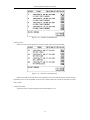
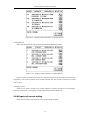
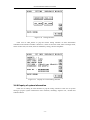
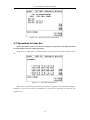
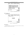
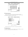
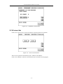
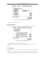
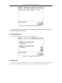
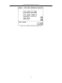
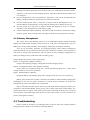
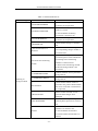
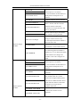
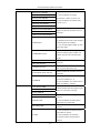
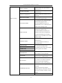
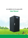
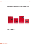
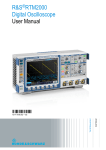
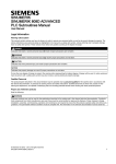
1
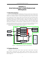
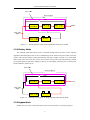
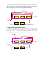
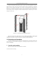
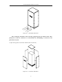
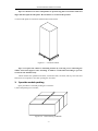
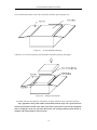
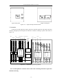
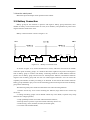
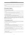
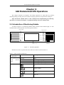
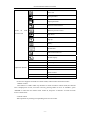
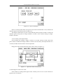
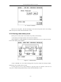
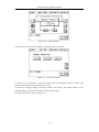
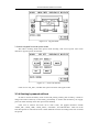
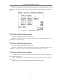
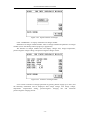
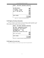
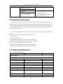
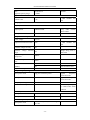
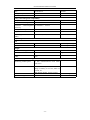
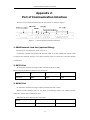
Preface Our company is engaged in developing and manufacturing products of uninterrupted power system which is a kind of power product with high quality and can meet various performance requirements. Note: This manual contains instruction of mounting, application, and operation of UPS. It shall read this manual carefully before mounting the system and it shall not take any operations on UPS before finishing reading all safety instruction and operation instruction. This manual contains significant information, please obey all warnings and operation instructions stated by the manual and machine, and the manual shall be kept well. Safety: The uninterrupted power system must be grounded before operation. Battery shall be replaced by qualified maintenance personal. The battery is toxic waste according to laws, so wasted battery shall be recovered by its classification in accordance with requirement of environmental protection. Warning: Selling of this product is only for partner who has general information on UPS products. It is necessary to know some other mounting requirements or measures to prevent accident. Any content of the manual shall not be modified without allowance of manufacturer and any offenders must be investigated. Our company reserves the right of final interpretation. CATALOG CHAPTER 1: BRIEF INTRODUCTION OF 660 MODULARIZED UPS SYSTEM.................. 1 1.1 Brief Introduction................................................................................................................ 1 1.2 System Structure ................................................................................................................. 1 1.3 Operating Mode .................................................................................................................. 2 1.4 Functions and Characteristics ............................................................................................. 5 CHAPTER 2: MOUNTING OF 660 MODULARIZED UPS.......................................................... 6 2.1 Environmental Selection ..................................................................................................... 6 2.2 Venue Layout ...................................................................................................................... 6 2.3 Unloading and Unpacking................................................................................................... 7 2.4 Cable Selection and Connection ....................................................................................... 11 2.5 Battery Connection ........................................................................................................... 13 2.6 Mounting of Modules........................................................................................................ 14 CHAPTER 3: 660 MODULARIZED UPS OPERATIONS........................................................... 16 3.1 Introduction of Monitoring Module .................................................................................. 16 3.2 Operation for Turning On.................................................................................................. 18 3.3 Operation for Turning Off ................................................................................................. 24 3.4 Operation for Emergency Power Off ................................................................................ 26 3.5 Operation for Maintenance Bypass ................................................................................... 26 3.6 Enquiry Operation............................................................................................................. 27 3.7 Operations for User Set..................................................................................................... 36 CHAPTER 4: UPS REPAIRING AND MAINTENANCE ............................................................. 43 4.1 UPS Repairing and Maintenance ...................................................................................... 43 4.2 Troubleshooting ................................................................................................................ 44 4.3 Maintenance Assurance..................................................................................................... 49 4.4 Technical Specifications.................................................................................................... 49 APPENDIX 1: LAMP SIGNAL REFERENCE LIST...................................................................... 53 APPENDIX 2: PORT OF COMMUNICATION INTERFACE ..................................................... 55 660 modularized UPS user manual Chapter 1: Brief Introduction of 660 Modularized UPS System 1.1 Brief Introduction 660 is a kind of high-frequency modularized UPS power with three-inlet and three-outlet offered by our company, full digital control technology is applied for the product, and the single cabinet can be extended to 160 KVA / 128 KW. The modularization design is used for the overall unit, including power module, charger module, and monitoring module, and all modules support hot-plugging operation. The modularization design is used for all modules of the overall unit which ensures compactedness of layout and improves reliability of overall unit; full isolation of damaged components and air flue is achieved inside the power module and charger module which improves reliability of overall unit further; in addition, advanced “N+X” wireless parallel connection redundant technique is used for the overall unit which reduces probability UPS single point fault farthest so that the reliability design of overall unit is trending to be perfect. Schematic diagram of overall unit is shown in figure 1.1: Figure 1.1 Schematic Diagram of 660 Overall Unit Product 1.2 System Structure Components of the system mainly include: input breaker, output breaker, maintenance bypass breaker, communication port, charger module, monitoring module, power module, lightening protection breaker, and lightening protection device, etc. Its system structure chart is shown in figure 1.2: -1- 660 modularized UPS user manual Figure 1.2 System Structure Chart 1.3 Operating Mode 660 UPS is a kind of online double-conversion UPS, its working modes are as follows: Main power supply mode (line mode) Battery mode Bypass mode Maintenance mode (manual bypass) Frequency transformer mode 1.3.1 Main Power Supply Mode The working mode that alternating current power of overall circuit for UPS power module is supplied by main power, direct current power for inverter is supplied after corrected by PFC power factor, and continuous and uninterrupted alternating current power for load is provided by inverter circuit is called main power mode. The charger module can be started under main power mode and the battery can be charged by main power through charger module. -2- 660 modularized UPS user manual Figure 1.3 Working Process Chart for Single Module under Line module 1.3.2 Battery Mode The working mode that battery power is boosted through battery booster circuit, and then supplied to load through inverter circuit is called battery mode. When main power fault occurs, the system will switch to battery mode automatically and power supply for load is not interrupted. When main power recoveries, the system will switch to main power mode automatically without any manual operation and power supply for load is not interrupted. Switching time of main power mode and battery mode is 0 ms. Figure 1.4 Working Process Chart for Single Module under Battery Mode 1.3.3 Bypass Mode If fault such as inverter circuit fault and inverter circuit overload, or switching to bypass -3- 660 modularized UPS user manual mode by hand occurs, the power module will switch the load from side of inverter circuit to side of bypass and power supply for the load is not interrupted. Charger module can be started under bypass mode, the battery can be charged by main power through charger module. Figure 1.5 Working Process Chart for Single Module under Bypass Mode 1.3.4 Maintenance Mode (Manual Bypass) If it needs to maintain or repair the UPS, it can close the manual bypass switch to switch the UPS to the side of maintenance bypass and the power supply for load is not interrupted. In that case, the main power will not pass the internal components of machine but connect the input terminal and output terminal directly so that we can maintain or repair the UPS. Figure 1.6 Working Process Chart under Maintenance Bypass Mode -4- 660 modularized UPS user manual 1.3.5 Frequency Transformer Mode UPS can be set to be frequency transformer mode which can provide stable frequency output of 50 Hz or 60 Hz. Input frequency range of main power is 40 Hz ~ 70 Hz. UPS will output the set output frequency and the bypass mode is ineffective under frequency transformer mode. When main power is abnormal, the system will switch to battery mode automatically and still output with the setting output frequency. 1.4 Functions and Characteristics DSP full digital control technology; Pure online double-conversion framework, strong load capability; All modules support hot-plugging technology; Internal integrated power system of cabinet is convenient for mounting and can save user’s investment; Input power factor is as high as more than 0.99, low harmonic current, environmental protection, high-efficient, and energy saving; Wide input voltage range, 50/60 Hz power system self-adoption suitable for all grid under any circumstance; Support frequency mode of 50 Hz input / 60 Hz output and 60 Hz input / 50 Hz output which can meet special requirements of user; “N+X” wireless parallel connection redundant technique can set number of parallel machines by LCD screen; Parallel machines share the battery group which can save cell investment from user; Single power module capability is 20 KVA / 16 KW, the overall unit can be extended to 160 KVA / 128 KW, and the maximum charging current is 60A; Flexible charging parameter setting and battery configuration, charging current can be set from 0 – 60A, and pieces of battery can be 32 – 40; Advanced battery intelligent management technology (three-stage intelligent charging, compensation factor of battery temperature, etc.) can prolong working life of battery effectively; Support cold start of battery and automatic start of normal power which can meet user's application requirements; Easily damaged components are completely isolated with air flue which can improve reliability of the system effectively; Easily damaged components can be changed in module level, field replacement is fast and convenient and module cost is low; Front operation combining with upper and lower line is convenient for connection; Perfect hardware and software protection function (level C lightening protection, breaker, Fuse, hardware protection, and software protection), super self diagnosis, and rich historic record enquiry; 5.7 inch LCD touch wide screen display, friend human-computer interface; Many communication ports, including RS232, RS485, USB, dry contact card and SNMP card. -5- 660 modularized UPS user manual Chapter 2: Mounting of 660 Modularized UPS 2.1 Environmental Selection Placed location must be stable; Enough ventilation space must be left between all surfaces of UPS machine and walls; Be far away from hot source and corrosive materials, avoid the sunshine; Keep normal working temperature and elevation height (working temperature: 0℃ ~ 40℃, it needs to be applied by derating if elevation height exceeds 1500m); Keep clean working environment, avoid environment with moisture, flammable gas, flammable liquid, or corrosive material; Weight capability of floor to machine and battery group shall be considered before mounting. 2.2 Venue Layout It needs to put the expansion bolts into foundation when placing the UPS in order to ensure stability of UPS, and then tighten the expansion bolts after the cabinet is placed stably. Its locating data is shown in figure 2.1 (unit: mm): Front Door of Cabinet Figure 2.1 Bedplate Chart of Cabinet Long of cabinet is 1000 mm, width is 600 mm, long of space between fastening screws is 371 mm and width of that is 740 mm. -6- 660 modularized UPS user manual Location of placing the UPS shall be proper in order to ensure safety application of UPS. It shall be placed in place with clean environment without moisture, flammable gas, flammable liquid or corrosive material and sunshine. User can put it on assigned location with assistant of human force or equipment and shall pay attention to spaces between UPS and surrounding things when mounting so that it is helpful for ventilation and heat dissipation. Minimum space is shown in figure 2.2 (unit: mm): 800 700 800 Figure 2.2 Scale Map of Mounting Field of Cabinet Tips: do not insert any object into air vent or other open mouth to ensure good ventilation environment so that it is benefit for ventilation and heat dissipation. 2.3 Unloading and Unpacking User shall check the package to confirm it is undamaged after receiving the product; then open the package to check whether the equipment is undamaged, and please contact the carrier at once if it is damaged. 1. Open the system packing Open the wood box firstly, and its methods are as follows: 1) Put the wood box vertically; -7- 660 modularized UPS user manual Figure 2.3 Wood Box Placement Tips: it shall pay attention to that wood legs supporting the box shall be down when placing the wood box, otherwise it is inconvenient for dismantling of wood box and placement of system. 2) Open the top plate of wood box and then take out the foam; Figure 2.4 Unseal the Wood Box -8- 660 modularized UPS user manual Tips: use slotted screw driver and pincher to open the top plate of wood box with steel edges and then open the side plates. Be careful for no scratch of the product. 3) Unseal side plates of wood box and then take out the foams. Figure 2.5 Unsealed Cabinet Tips: it can place the cabinet to mounting location by removing crews connecting the cabinet and wood supports after unsealing. It shall be careful when unsealing to prevent scratch for the machine body. Check whether the qualified certificate, instruction book, CD disk, and keys for front and back doors are complete or not after opening the wood box. 2. Open the module packing Open procedures of module packing are as follows: 1) Place the packing box in stable; Figure 2.6 Outer Packing of Module -9- 660 modularized UPS user manual 2) Cut off the plastic belts, remove the scotch tape, and then open the paper box; Figure 2.7 Unseal the Module Packing 3) Remove cover of foam packing, the equipment with plastic packing will appear; Figure 2.8 Taking out of Module 4) Finally, take out the equipment with plastic packing, and then remove the plastic packing. Tips: appendixes along with cabinet and modules shall be kept well, especial that the manual and CD disk contain much safety instruction, please do not operate the equipment before reading the whole safe operation instruction. All warnings and operations shown by machine and manual shall be obeyed strictly. - 10 - 660 modularized UPS user manual 2.4 Cable Selection and Connection 2.4.1 Cable selection When selecting connecting cable for the system, it is suggested to select wire diameter of cable according to maximum power configuration of 660 system and complying local connection rules and environmental condition (temperature and physical support media). The cable shall be selected according to maximum steady-state alternating and direct currents of 660, and its selection conditions are listed in table 2.1: Table 2.1 Cable Current Table Rated 380V input UPS rated power Input current when it is full load and charger module outputs maximum power Output current when it is full load Current of 32 pieces batteries 160 KVA 232A 242A 420A 2.4.2 Cable connection Inlet and outlet channels of 660 cabinet are shown in figure 2.9: Front door Input wire channel Figure 2.9 Output wire channel Vertical View of Cabinet Main power input cable and battery are connected with UPS through input channel, UPS and load is connected by load output cable through output channel. Connection of cable is: 1. Open the UPS input and output switch panels to expose the copper rows. - 11 - 660 modularized UPS user manual Input switch panel Output switch panel Figure 2.10 Input and Output Switch Panels 2. Connection Connect the normal input line, battery input line, and load output line with UPS connection terminals through input and output line channels of cabinet according to phase order shown in figure 2.11. Bat+ Bat zero BatMain power S Main power N Main power R Main power T Ground Output S Output N Output R Output T Figure 2.11 Input and Output Wiring Boards Note: it shall tighten the terminals with wrench when connecting and check it again after finished connecting. - 12 - 660 modularized UPS user manual 3. Mount the switch panel Mount the input and output switch panels into the cabinet. 2.5 Battery Connection Battery group for this machine is positive and negative battery group framework, total number of battery can be selected from 32 to 40 (even numbers), and quantities of positive and negative batteries shall be the same. Battery connection chart is shown in figure 2.12: Figure 2.12 Battery Connection Chart As shown in figure 2.12, connect all batteries in series, and lead a zero line from middle connection point of battery groups, so it shall be three lines together with positive and negative ends of battery group to connect with battery connecting terminals of UPS. Batteries between positive end of battery group and zero line are called positive batteries, and batteries between negative end of battery group and zero line are called negative batteries. User can select the capability and number of battery according to its demand. It must add an DC breaker between battery group and UPS to play a role of current-limiting protection and open and close the battery group when maintaining. The following safety notes shall be noted all the time when mounting batteries: 1. Electric shock may occur when mounting the batteries, high short-circuit current may cause fire; 2. Voltage of battery groups can be 480Vdc which may cause death, so please obey safety attentions for voltage operation; 3. Only qualified personal can mount and maintain the batteries; 4. Wear protective eyewear to prevent accident caused by electric arc; 5. Take off ring, watch, necklace, bracelet, and other aglets; 6. Use tools with insulated hands; - 13 - 660 modularized UPS user manual 7. It shall break down the breaker of battery when connecting lines between UPS and battery. It must ensure that the sequence and polarity of connection are correct after finished connection; 8. Please contact customer service department of our company if the user needs to change the number of used batteries during normal application. Please do not operate it solely. 2.6 Mounting of Modules 2.6.1 Steps of module mounting 1. Take off decoration panel in front face of vacant slot of module needing to be mounted on the cabinet. 2. Insert the charger module and power module into corresponding module slot from upper to lower (mounting according to corresponding locations shown in figure 1.2). 3. There is a screw positing hole in both sides of module, fix the module with screws dismantled from panel on cabinet. 4. Screw fixing the module must be specific Huangguan screw (M5*16), otherwise it may damage inner switch of cabinet or cause the machine cannot be turned on. Note: it shall push slowly so that the module can be inserted into the cabinet completely when inserting the module into UPS. It shall pay attention to that connecting terminal between them shall be inserted tightly without overexert, otherwise it may damage the contact pin of terminal. 2.6.2 Hot-plugging of module 660 modularized UPS supports hot-plugging of module which can take online hot-plugging for all modules. UPS can monitor connection conditions of all modules at any time and turn on or off the modules according to connection condition of them 1. Insertion of module 1) Mount the UPS module into corresponding blank plot of cabinet, and then push the module into the cabinet until it is inserted into the cabinet completely. 2) Use specific Huangguan screws to lock the screw location holes in two sides of module panel tightly (screw in left side must be fastened within 30s after the module is inserted). 3) The UPS will start automatically if new module is detected, the starting is finished after a period time, and then the module is turned on. 4) When adding new module for battery module, it shall press the button of “ENTER” on control panel for 2s after the module is pushed into cabinet and screw is fastened, and then the module can build working power and turn on automatically. 2. Extraction of module Take off the screw of UPS module panel to stop running of the module, and then extract it after fan of the module stops rotating. - 14 - 660 modularized UPS user manual Note: 1. Positioning screw hole in left side of module controls the running of module, so special screw shall be used. It shall fasten this screw within 30s after the module is pushed into cabinet. 2. The power module shall be pushed into cabinet after 30s since it is extracted, otherwise it may cause fault for the system. 3. All modules shall be mounted according to corresponding locations shown in figure 1.2, otherwise it may cause the machine cannot be turned on. - 15 - 660 modularized UPS user manual Chapter 3: 660 Modularized UPS Operations This chapter describes all enquiries and setting operations of UPS taken by operator, including starting of UPS, power off of UPS, all enquiry operations, and parameter setting, etc. Tips: instruction manual must be read carefully before implementing the following operations to avoid personal injury or equipment damage caused by misoperation. 3.1 Introduction of Monitoring Module As shown in figure 3.1, monitoring module mainly contains: LED indicator light, 5.7 inch multifunctional LCD touch wide screen and operation button. Indicator light Operation button TAB FAULT UP BYPSS DOWN BATTERY ENTER NOMAL CANCEL EPO COLD START LCD wide screen Cold start Figure 3.1 Monitoring Module Definitions of icons on panel silk-screen and LCD screen are listed in table 3.1: Table 3.1 Silk-screen/Icon Illustration Monitoring module panel LED light indicator Icon/Silk-screen Meaning FAULT Warn BYPASS Power supplied by bypass BATTERY Power supplier by battery NOMAL Power supplied by main power Set Charger module Battery Power on - 16 - 660 modularized UPS user manual Power off Input parameter Output parameter Return to main interface Return to previous menu Icons on LCD touch screen Page down Page up History Module data Self-test and mute off Record enquiry Operation buttons TAB Switch of touch/button-control UP Cursor up DOWN Cursor down ENTER Confirm CANCEL Return to button-control COLD START Cold start EPO Emergency power off touch-control from LCD screen supports two kinds of control modes, button control and touch control. 1. Button control Press button of “TAB” under any interface to switch to button control mode, the selected icon is displayed in reverse, move the cursor by pressing button of “UP” or “DOWN”, press “ENTER” to select the icon where cursor locates at, and press “CANCEL” to return to touch screen control mode. 2. Touch control Take operations by clicking corresponding icons in LCD screen. - 17 - 660 modularized UPS user manual 3.2 Operation for Turning On It shall check whether all screws are fastened and all connections are correct or not before starting the machine. Input, output, and battery breakers shall be in off state. 3.2.1 Start under main power mode 1. Start main power mode directly 1) Connect the main power Close input breaker to connect the main power. The UPS screen starts to work then and initializer Interfac occurs. Figure 3.2 initializer Interface It will be refreshed to main interface after 1s. Figure 3.3 Main Interface 2) Start UPS Click icon of power on in main interface to pop the interface of power on. Click icon of “TO_INV” and then UPS starts to power on under main power. - 18 - 660 modularized UPS user manual Figure 3.4 Power on interface Process of starting UPS under main power mode will be finished after a time, and then the indicator light in front panel of power module is on. The charger module starts to power on automatically after the power module is started, the indicator light in front panel of charger module is on after a time, and the starting of charger module is finished. 3) Close battery and output breakers Check whether the charging voltage is normal or not after starting of UPS under main power mode is finished and charger module is started, close the battery and output breakers if it is normal, and then the UPS will be in normal operation. Energy flow after started under main power mode is shown in figure 3.5: Figure 3.5 Operations under Normal Power 2. Switch Bypass mode to Line mode If the module is working under bypass mode, click the power on icon in main interface to pop the power on interface. - 19 - 660 modularized UPS user manual 3.6 Power on interface Click icon of “TO_INV”, the UPS will begin to start the main power mode. And starting under main power mode will be finished after a time. 3.2.2 Starting under battery mode If main power is fault, UPS can be turned on by battery mode directly. 1. Close battery and input breakers, and connect the batteries. 2. Press button of “COLD START” in monitoring module panel to turn on the LCD screen. LCD screen displays main interface. Figure 3.7 Main Interface 3. Press “ENTER” for 2s to build working power for power module and charger module, and then the fan of module starts to rotate. 4. Click power on icon in main interface to pop the power on interface. Click icon of “TO_INV”, and the starting under battery mode will be finished after a time. - 20 - 660 modularized UPS user manual Figure 3.8 Power on interface 5. Close output breaker, and then the UPS output is normal and starting by battery is finished. Its energy flow is shown in figure 3.9: Figure 3.9 Battery Mode 3.2.3 Starting under bypass mode It can switch to bypass mode directly under main power mode or under standby mode (it is not allowed to switch to bypass mode directly in the case that the main power is available, but UPS has not been turned on with a isolating transformer connected to output). 1. Switch to bypass mode under standby mode(The main power is available, but UPS has not been turned on). The UPS has not been started currently, and display of its main interface is shown in figure 3.10: - 21 - 660 modularized UPS user manual Figure 3.10 Main Interface 1) Click power on icon in main interface to pop the power on interface. Figure 3.11 Power on interface 2) Click icon of “TO_BYP” to enter the bypass mode, and the bypass mode is started. The charger module will start automatically after a time. 4) Check the charging voltage of charger module, close battery and output breakers if the charging voltage is normal, and the bypass starts normal output. Its energy flow chart is shown in figure 3.12: - 22 - 660 modularized UPS user manual Figure 3.12 Bypass Mode 2. Switch to bypass from main power mode The UPS is working under main power mode currently, click icon of power off in main interface to pop the power off interface. Figure 3.13 Power off interface Click icon of “TO_INV”, and then the system will enter into bypass mode. 3.2.4 Starting by manual self-test In order to ensure the battery state of UPS and prolong working life of battery, it needs to charge and release electricity of the battery periodically to ensure that the battery can supply power for UPS normally when main power fails suddenly. Click icon of self-test and mute off in main screen, the popped interfaces include “TEST_10S”, “TEST_10M”, “TEST_LOW”, “CANCEL”, and “MUTE OFF”. Click one of the first three options to select the test time. Select different test times according to the time of actual test period. - 23 - 660 modularized UPS user manual Figure 3.14 Self-test and Mute off Interface 3.2.5 Start of charger module Note: it needs to set the parameters of charger module and ensure that the pieces of battery and group can match with the connected battery groups before starting. (It shall be set by professional personal of the company) 1. Charger module will start automatically to charge the battery when UPS is started under main power mode or bypass mode. 2. If the charger module is off and needs to be restarted when the UPS is in main power or bypass mode, it can click the power on icon in main interface to pop the power on interface, click icon of “CHG_ON” below the “CHARGER POWER ON?”, and then the charger will be started. Starting of charger module is finished when the indicator light in charger module panel is on. Figure 3.15 Power on Interface of Charger Module 3.3 Operation for Turning Off 3.3.1 Power off under line module The UPS is working under main power mode currently. - 24 - 660 modularized UPS user manual Click icon of power off in main interface to pop the power off interface. Click icon of “OFFUPS” to power off the UPS, and the charger module will off automatically at the same time. Figure 3.16 Interface of Power Off 3.3.2 Power off under battery mode The UPS is working under battery mode currently. Click icon of power off in main interface to pop the power off interface. Click icon of “OFFUPS” to power off the UPS. 3.3.3 Power off under bypass mode The UPS is working under bypass mode currently. Click icon of power off in main interface to pop the power off interface. Click icon of “OFFBYP” to power off the UPS, and the charger module will be off at the same time. 3.3.4 Power off the charger module 1. The charger module will be off automatically if the machine is powered off under main power mode or bypass mode. 2. Power off the charger module when the machine is working under main power mode or bypass mode: 1) Click icon of power off in main interface to pop the power off interface. - 25 - 660 modularized UPS user manual Figure 3.17 Power Off Interface 2) Click icon of “OFF” below “POWER OFF CHARGER?” to power off the charger module. 3.4 Operation for Emergency Power Off Emergency power off (EPO) switch is used to power off the UPS under emergency situation (such as fire, flood, etc.). Press button of EPO in monitoring module, the UPS will cut off output at once and cut off the power in several seconds. If it needs to power on the machine again, it shall take the power on operation after cutting off the normal input for 30s. 3.5 Operation for Maintenance Bypass 3.5.1 Starting of maintenance bypass 1. Select option of power off in LCD main interface, select icon of “TO_BYP” in power off interface, and confirm the UPS is working under bypass mode in LCD screen. Figure 3.18 Bypass Mode - 26 - 660 modularized UPS user manual 2. Open the cover of breaker of maintenance bypass, close the breaker of maintenance bypass, cut off the output and battery breakers, and then the UPS enters into maintenance bypass mode. Its energy flow is shown in figure 3.19: Figure 3.19 Maintenance Bypass Mode Cut off the input breaker and you can take the maintenance operations. 3.5.2 Exit of maintenance bypass mode 1. Close the input breaker, the power modules builds working power, and then turn on the bypass mode, charger module starts automatically, and indicator light in front panel of module is on. 2. Close the output and battery breakers, cut off maintenance bypass breaker, put the baffle of maintenance bypass breaker, and then the warning “maintenance cover is open” in LCD screen disappears. 3. Select option of power on in LCD main interface, select “TO_INV” in power on interface, the power module will start the inverter after 20s, and then UPS will be working under line mode. 3.6 Enquiry Operation Enquiry operation is a parameter to inquiry the working condition and setting of UPS. 3.6.1 Enquiry of input information Click “I\P” in main interface to pop the input parameter interface. The input parameter interface will display information including input voltage, input frequency, bypass voltage, and bypass frequency, etc. - 27 - 660 modularized UPS user manual Figure 3.20 Input Parameter Interface 3.6.2 Enquiry of output information Click “O\P” in main interface to pop the output parameter interface, and then information including output voltage, output current, output frequency, active power, apparent power, and load factor, etc. will be shown. Figure 3.21 Output Parameter Display 3.6.3 Enquiry of information of power module Click module data icon in main interface to pop the module information interface. - 28 - 660 modularized UPS user manual Figure 3.22 Chart of Module Information Interface LCD screen will display the module at corresponding position if the power module is inserted into plot of cabinet; it means no power module is inserted into the plot if nothing is displayed in LCD screen. If the panel screw is not locked or not fastened after mounting of module, the module will pop the warning of “EPO ACTIVE”, and it cannot take operations of power on then. Click icons of “MODULE 1” to “MODULE 8” in “MODULE INF” interface to inquiry data information of every module. The information includes: three-phase input voltage, bypass voltage, output voltage, output current, input frequency, output frequency, and module temperature. It can switch data information of every module by button of page up or page down. Figure 3.23 Data Interface of Single Module 3.6.4 Enquiry of information of charger module Click icon of charger module in main interface to pop option interface of charger module. - 29 - 660 modularized UPS user manual Figure 3.24 Option Interface of Charger Click “CHARGER 1” to inquiry information of charger module. Information of charger module includes: status of charger module and parameter of charger module (can be switched by button of page up or page down). The interface of charger module state will display: charger state, charger temperature, positive/negative charger voltage, and positive/negative charger current. Figure 3.25 Interface of Charger Status It can switch to interface of charger parameter by pressing button of page up or down, and the following information will be displayed: float charge voltage, even charge voltage, temperature compensation setting, positive/negative charging rate and maximum positive/negative charging current. - 30 - 660 modularized UPS user manual Figure 3.26 Interface of Charger Parameter 3.6.5 Enquiry of battery information Click icon of battery in main interface to enter into interface of battery parameter. It will display: number of battery, groups, connection state, battery voltage, battery remain time, battery remain capability, battery temperature, time of next self-test. Figure 3.27 Display of Interface of Battery parameters 3.6.6 Enquiry of current warn Click icon of “WARN” in main interface to pop current warning information. - 31 - 660 modularized UPS user manual Figure 3.28 Warn Interface 3.6.7 Enquiry of history Click icon of module data in main interface to pop the interface of module data, and then click icon of history to pop the interface of UPS history. It contains: “fault ”record, “operate ”record, “warn” record, and “status” record. Figure 3.29 Interface of History 1. Fault record: “Fault record” records all faults occurred during operation of UPS. - 32 - 660 modularized UPS user manual Figure 3.30 Interface of Fault Record 2. Warn record “Warn record” records reasons for all warns when warns occurred for UPS. Figure 3.31 Interface of Warn Record Fault record and warn record can record 2940 pieces at most and the earliest records will be replaced by new record if number of all records exceeds 2940. All records are listed by inverted order of time. 3. Operate records “Operate record” records all operations of UPS taken by user. - 33 - 660 modularized UPS user manual Figure 3.32 Display Chart of Interface of Operate Record 4. Status Record Status record records all working mode of UPS under different periods. Figure 3.33 Display Chart of Interface of Status Record Operate record and status record can save 768 pieces at most and the earliest records will be replaced by new record if number of all records exceeds 768. All records are listed by inverted order of time. 5. Enquiry record Click icon of enquiry record in any record interface to pop the interface of record enquiry. Enter the record time, it can inquiry records before and after the entered time. 3.6.8 Enquiry of current setting Click icon of setting in main interface to pop the setting interface. - 34 - 660 modularized UPS user manual Figure 3.34 Setting Interface Click icon of “SET_INFO” to pop the current setting interface of UPS. Information contained in the interface includes: cabinet No., status of converter mode, status of charge mode, status of auto start, test mode, status of redundancy setting, and user telephone. Figure 3.35 Display of Current Setting Interface 3.6.9 Enquiry of system information Click icon of setting in main interface to pop the setting interface. Click icon of system setting to pop the system information of the machine, including: sequence No., module and software edition. - 35 - 660 modularized UPS user manual Figure 3.36 Interface of System Information 3.7 Operations for User Set Warn: operation for user set is used for setting UPS parameters, and nonprofessional personal shall not take any setting operations. Click icon of “USER_SET” in setting interface to pop the password input interface of user set. Figure 3.37 Password Input Interface Enter correct password (initial password is 666666) to pop the user set interface, including: language set, time set, auto test set, redundancy set, protocol set, password set, touch set, and telephone set. - 36 - 660 modularized UPS user manual Figure 3.38 User Set Interface 3.7.1 Language set LCD screen of 660 series can provide one languages:English, for option. Figure 3.39 Language Set Interface 3.7.2 Time set Click icon of “TIME SET” in user set interface to enter into time set interface. It can change the displayed time of UPS by entering current time. - 37 - 660 modularized UPS user manual Figure 3.40 Time Set Interface 3.7.3 Auto self-test set Click icon of self-test setting in user set interface to pop the self-test set interface. Its display is shown in figure 3.41, auto self-test interface includes: on and off of self-test, run cycle of self-test, and duration of self-test for every time. Figure 3.41 Self-test Set It shall select proper self-test duration and time according to personal requirement. 3.7.4 Redundancy set Click icon of “redundancy set” in user set interface to enter into redundancy set interface. Enter number of redundancy group to confirm redundancy of UPS. - 38 - 660 modularized UPS user manual Figure 3.42 Redundancy Set Interface 3.7.5 Protocol Set Click icon of “protocol set” in user set interface to pop the protocol set interface. Figure 3.43 Protocol Set Interface There are two optional communication ports, “RS232” and “RS485”. Click icon of “RS232”, and then communication port set interface will be popped. - 39 - 660 modularized UPS user manual Figure 3.44 Communication Port Set Interface Port property shall be set by demand. 3.7.6 Password set Click icon of “password set” in user set interface to pop the password set interface. Figure 3.45 Password Set Interface The password is required when entering user set interface. Enter original password and new password to change the password (initial password is 666666). 3.7.7 Touch set If the touch click is not so sensible, it can recover the sensitivity of touch screen through touch set. Click icon of “touch screen set” in set interface to pop the calibrate interface of touch screen. Click specified site according to order, and then the sensitivity of touch screen will be recovered. - 40 - 660 modularized UPS user manual Figure 3.46 Calibrate Interface of Touch Screen Note: object used to click the touch screen shall not be too sharp when taking touch set, otherwise it will damage the screen. 3.7.8 Telephone set It can change the contact telephone of user by telephone set. Figure 3.47 Telephone set interface 3.7.9 Mute off Click icon of battery self-test and mute off in main interface to pop interface of battery self-test and mute off. Click “MUT OFF” in self-test interface to mute the warning sound. - 41 - 660 modularized UPS user manual Figure 3.48 Interface of Self-test and Mute off - 42 - 660 modularized UPS user manual Chapter 4: UPS Repairing and Maintenance 4.1 UPS Repairing and Maintenance 4.1.1 Power and features of load shall be considered when using UPS Rated output power of UPS is the key parameter to express how much power load the product can drive, it changes along with alteration of load power factor, for example, 1 Kva UPS maybe cannot drive 1 Kva load. UPS shall not be under full load condition for long in order to prolong working life of UPS. Load capability of standby UPS shall be 60%~70% of rated power, and that of online UPS shall be 70%~80% of rated power. At the same time, the UPS shall not work under over under-loading condition for a long time. 4.1.2 Ensure induction stroke protection of UPS Lightening stroke is the natural enemy of all electrical equipments, so it must ensure the effective shielding and ground protection of UPS against lightening stroke. Lightening stroke may cause inductive high potential pulse due to electromagnetic induction. The high potential pulse may enter into the UPS along with power line or communication line, while there are so many microelectronic devices such as CMOS integrated circuit modules and CPU used for control in the UPS which are very sensitive to electromagnetic pulse of lightening, therefore, the devices are very easy to be damaged. Although our UPS has effective shielding and good protection ground measure, user still needs to adopt lightening protection of over-voltage protection for power line and communication line (such as remote monitoring signal line). 4.1.3 Notes for using, repairing and maintenance It must obey the product introduction when using UPS. Related stipulations in using manual can ensure all firing lines, zero lines, and earth lines meet requirements, so user shall not change its order without allowance. Any operation shall strictly comply with correct order of power on and off. It shall avoid excessive fluctuation of voltage output of UPS caused by sudden increasing or reducing of load so that the UPS cannot work in normal. It is strictly forbidden to power on and off the UPS frequently. It requires for 30s after the UPS is powered off and before starting it again, otherwise, fault may occurred for UPS. It is forbidden to operate under over-load. Maximum starting load of UPS shall be controlled within 80%, and the inverter may be damaged under inverter condition if it is operated under over-load condition. Experience proves that the best operation mode is to control the load within 30~60% of rated output power for most UPS powers. Discharging requirement of battery: in general, the UPS is equipped with protection measures for discharging of battery, but the battery will recover to certain voltage after it is - 43 - 660 modularized UPS user manual discharged so that the protection is powered off, and it is not allowed to restart the machine, otherwise, it may cause over-discharging of battery. The battery shall be used normally after it is recharged. For new bought UPS (or for UPS stored for a long time), it only can be operated after the battery is charged. Otherwise, the backup time will not be ensured. For UPS without power off for a long time, its battery shall be discharged for every 3~6 months and then recharged again. It can prolong the working life of battery by this way. For UPS stored for a long time, it shall be started and charged for every 3~6 months, otherwise, it may damage the host and battery of UPS. It shall maintain the UPS periodically. Clean dust inside the machine, measure the voltage of battery group, check running of fans, and inspect and adjust system parameters of UPS. 4.1.4 Battery Management This system allows the charging system to be an independent charger module with high liability and without high frequency clutter which can avoid effect of high frequency wave to battery life; avoid overheat of battery when charging, and prolong working life of battery. User can set the battery parameter by monitoring display screen (battery management parameter shall be set by professional personal, please notify the customer service personal if user needs to change these parameters), and the system can take intelligent management for battery according to user set and actual status of battery group. Charge mode of 660 system is three-stage charge: Stage 1: re-charge 90% capability of battery Charge with equalizing charging voltage and maximum charging current; Stage 2: re-charge the balance 10% capability of battery Turn to stage 2 to equalizing charge for 1 minute and floating charge for 1 minute when voltage reaches to 13.85V of every battery. Stage 3: Maintain battery capability Charge the battery with floating charge when voltage reaches to 14.25V of every battery. Battery group of 660 series product is shared by all modules in UPS (including charging and discharging). It can use one group of batteries or several groups of batteries to increase the backup time of system according to user’s requirement. Tips: it must take off metal objects such as ring and watch before changing the battery, use screwdriver with insulated handle, do not put any tool or other metal object on the battery. It is normal phenomenon to appear small spark at joint when connecting the battery, but it will not cause any harm to personal safety and UPS. Do not cause short circuit or reverse connection on positive and negative of battery. 4.2 Troubleshooting Faults of UPS can be known by inquiring history records of UPS, and common problems during operation of UPS can be solved by contrasting table 4.1. - 44 - 660 modularized UPS user manual Table 4.1 Fault/warn Removal Problem Type Warning of charger module Fault/warning Solution BAT OVERCHARGED Power off the charger and contact customer service personal. BAT DISCONNECTED Check whether the external battery breaker is closed 2. Check whether the battery connection is normal or not BAT CGARGERFALL Power off the charger and contact customer service personal CHAEGER OFF Check whether charger is started or not CAN communication is abnormal Check whether the connecting line of corresponding charger module is connected well Disconnect the monitoring module 1. If the monitoring module is connected, please check whether the connecting line of monitoring module is connected well 2. Please insert monitoring module if the monitoring module is not connected. LCD ERRORVOLTSET Contact customer service personal to change the set. LCD ERRORCURRSET Contact customer service personal to change the set. EPO ACTIVE Check whether button of EPO is pressed or not, please check whether the screw in left side is fastened if it is not pressed. CHG FANLOCK Please contact customer service personal if the charger fan is damaged LINE PHASEERR Check whether the phase sequence of three-phase input line is correct or not NLOSS 1. Check the back terminal of module is in normal or not. 2. Check whether the terminal connected cabinet and module is in normal. - 45 - 660 modularized UPS user manual 1. Check whether three-phase normal power is in balance. 2. Check whether the fluctuation of three-phase normal power is in normal. BUS OVER BUS UNDER BUS UNBALANCE BUS SHORT Contact customer service personal BUS SOFTTIMEOUT Pull out the module and insert it after 1 minute, and then start the machine. Please contact the customer service personal if it still not be powered on. BUCK SOFTTIMEOUT OVER TEMPERATURE LINE SCRFAIL Fault of charger module Short circuit of charger 1. Check connecting terminal of charger is short circuit or not; 2. Check port terminal of cabinet is short circuit or not. BAT REVERSE Check whether the battery connection is correct and correct it CHG IDERROR Check whether the set of dial switch in connecting panel of module of cabinet is 15 or 14. Please check dial codes of these two chargers are conflict or not if two chargers are used. 1. Check whether three-phase normal power is in balance. 2. Check whether the fluctuation of three-phase normal power is in normal. BUS VOLT HIGH BUS VOLT LOW BUS IMBALANCE Contact the customer service personal BUS SHORT BUS SOFTSTART FAIL INV SOFTSTART FAIL Fault of power module Power off the charger, and contact the customer service personal Cut off the input breaker, and start the machine after 30s. If fault occurred on single module, please take out the module and then insert again after 30s. Please contact the customer service personal if problem still exists. INVERTER VOLT HIGH INVERTER VOLT LOW - 46 - Contact the customer service personal 660 modularized UPS user manual RPHASE O/P SHORT SPHASE O/P SHORT TPHASE O/P SHORT RSPHASE O/P SHORT STPHASE O/P SHORT 1. Check whether the output connection is short circuit or not. 2. Check whether the load is short circuit or not. TRPHASE O/P SHORT R REACTIVE ABNORMAL S REACTIVE ABNORMAL T REACTIVE ABNORMAL Please contact the customer service personal. OVERLOAD 1. Power off secondary load 2. Reallocate the load so that outputs of three phases are balance. 3. Cut off UPS input breaker for 30s, then start again. OVERTEMP FAULT Ensure environmental temperature is within working range of UPS. Cut off the UPS for 30s, and then start again. REALY STICK DEATH LINE SCR FAULT Please contact the customer service personal. CAN BUS FAULT Check whether the communication line is connected well or not. TOTALREACTIVE FAULT Please contact the customer service personal. ID ERROR 1. Check whether set of dial switch in back of module is 1~8. 2. Check whether set of dial codes in back of module is conflict. LINE PHASE ERR Check whether the three-phase input lines are connected correctly. BYP PHASE ERR PHASE ERROR 1. Check whether the input power is normal. 2. Check whether the three-phase input lines are connected. PHASE LOSS BYPASS FAIL BPS FREQ ERR Check whether the input power is normal. N LOSS 1. Check whether the back terminal of module is normal. 2. Check whether the terminal connected cabinet and module is normal. - 47 - 660 modularized UPS user manual Other warning INPUT CB OPEN Check whether the input breaker is closed or not. OUTPUT CB OPEN Check whether the output breaker is closed or not. OUTPUT OVERVOLT Please contact the customer service personal. MAIN CB CLOSED Unnecessary for treatment under maintenance bypass mode CB COVER OPEN 1. Unnecessary for treatment under maintenance bypass mode. 2. Check whether the screw of maintenance cover is fastened or not under other working mode. BATVOLTLOW 1. Check whether the battery and charger are normal or not. 2. Check whether the battery set matches with actual configuration. 3. Please dismantle the secondary load as soon as possible if it is under battery mode. BATTERY OPEN 1. Check external battery breaker is closed or not 2. Check whether the battery is connected well OVLOAD FAIL 1. Close the secondary load 2. Reallocate the load so that outputs of three phases are balance. OVER CURRENT OVER LOAD REDUN OVLOAD EEPROM FAIL Forbidden to power on, and contact the customer service personal. FAN LOCK Contact the customer service personal if it is module fault. EPO ACTIVE Confirm whether the button of EPO is pressed or not. Please check the screw in left side of module is fastened or not if it is not pressed. CHARGER OFFLINE Check whether the charger is inserted. Insert and extract the charger module again to ensure the screw in left side of charger module is locked tightly. CAN FAIL Check whether the communication - 48 - 660 modularized UPS user manual line is connected well or not COMMSYNSIG FAIL COMMSYNPULSE FAIL Check whether the set of dial switch in connecting panel in corresponding module location of cabinet is correct or not. ID ERROR MODULE ID ERROR 4.3 Maintenance Assurance Under condition of complying rules of storage, mounting, using, and operation, we have liability to debug, repair or change elements and components timely free of charge if the product is damaged due to poor quality or improper option or cannot operate normally within three years since it is delivered; we have responsibility to provide paid life maintenance for the product if it is out of the warranty period. Service commitment of our company is: warranted for three years and maintained for all life. The following cases are not included in warranty range: 1. Artificial fault; 2. Out of warranty period; 3. Product whose production serial number is changed or lost; 4. Damage or loss caused by force majeure and external causes; 5. Dismantle or change the UPS without authority; 6. Breach operation/application stipulations of the machine; 7. The battery is discharged deeply or damaged by manual. 4.4 Technical Specifications Table 4.2 Technical Specifications Item Specifications Remarks Input parameters Input voltage Rated input voltage 380 VAC Input mode Three-phase five-wire system Bypass voltage range 380V*(1±20%) VAC Load ≤ 50% 204~520VAC 50% < load ≤ 70% 242~520VAC 70% < load ≤ 100% 277~520VAC Input power factor ≥0.99 Total harmonic (THDI) 8 UPS modules distortion ≤3% Input frequency AC main power input Settable 40~ 70Hz - 49 - 660 modularized UPS user manual Item Bypass frequency range Specifications 46~54Hz Remarks Input current Normal value 8 UPS modules full load 210A Output parameter Output power Output power 160kVA/128kW Load power factor 0.5 to 1 Every UPS 20kVA/16kW module Output electrical specification Rated voltage 380 VAC Output current normal value 242A Constant voltage accuracy 8 UPS modules full load ±1% Dynamic voltage transient ±5% range Change along with 0~ 100% load Output voltage direct current ≤100mV component Transient response recovery ≤40mS time Total harmonic (THDV) distortion ≤1% 100% resistive load ≤4% 100% nonlinear load 3:1 Maximum value Main power mode Keep pace with main power Support frequency conversion mode Battery mode 50/60 Hz Support frequency conversion mode Frequency tracking rate ≤1 Hz/s Phase lock accuracy 1° Normal frequency is 46~54Hz under stable condition Main power mode ≥93 % Full load Battery mode ≥93% Full load Output current peak factor Output frequency range Efficiency Overload capability Main power mode 110% < load ≤ 130%, switch to bypass after 10m - 50 - 660 modularized UPS user manual Item Specifications Remarks 130% < load ≤ 150%, switch to bypass after 1m load > 150%, switch to bypass after 0.5s 110% < load ≤ 130%, power off after 10m Battery mode 130% < load ≤ 150%, power off after 1m Load > 150%, power off after 0.5s Bypass mode Load ≤ 150%, working for long time load > 150%, power off after 10s Switching time Main power mode to battery 0ms mode Battery mode to main power 0ms mode Bypass mode to main power 0ms mode Main power mode to bypass 0ms mode Battery and recharger module Rated battery voltage Discharge off voltage 12V* pieces of battery Pieces of battery for every group is 16-20 10.2V* pieces of battery Battery overcharge protection 14.7V* pieces of battery voltage Float charging voltage 13.35* pieces of battery Even charging voltage 14.25* pieces of battery Maximum charging current 30 A Single charger module Full load DC input current 400 A 8 UPS modules Charging time Discharge capability within 2h can be recharged in 12h Parallel redundancy Quantity modules Quantity module of of paralleled redundancy 1 to 8 Can use single module 0 to 7 8 modules can power output full Environment condition Working temperature range 0~40℃ Working elevation height <1500m Working relative humidity 0~95% Shall be reduced using if exceeding this height - 51 - 660 modularized UPS user manual Item Specifications Storage temperature -15~45℃ Noise in 1m from surface <60dB Remarks Safety, electromagnetic compatibility Safety EN 62040-1-1 Electrostatic discharge IEC 61000-4-2 Level 3 electromagnetic IEC 61000-4-3 Level 3 Sustained sensitivity Voltage flash compatibility IEC 61000-4-4 Level 3 Surge interference IEC 61000-4-5 Level 4 Electromagnetic interference EN 62040-2 (>25A) class A (EMI) Physical specifications Size UPS cabinet 600 mm × 1000 mm × 2000 mm Width × depth × height UPS module 482 mm × 590 mm × 131 mm Width × depth × height Weight UPS cabinet (empty) 250kG UPS module 28kG Color Black Single UPS module Communication and management Monitoring module panel 5.7 inch multifunctional LCD touch wide screen Audible alarm Alarm of battery mode; warn when voltage of battery is too low; alarm of fan fault, etc. USB, RS232, RS485, and dry contact Standard configuration Port Optional management device SNMP card - 52 - 660 modularized UPS user manual Appendix 1: Lamp Signal Reference List Mode Fault/warning Status of LED Status of buzzer Phase sequence is error, and bypass is abnormal The fault light twinkles once 2s and lasts for 1/4s Buzz once 2s and last for 1/4s Battery disconnected The fault light twinkles once 4s and lasts for 1/4s Buzz once 4s and last for 1/4s No fault All is off No sound Some module is under fault mode The fault light twinkles once 1s and lasts for 1/4s Buzz once 1s and last for 1/4s Charger is not started The fault light twinkles once 8s and lasts for 1/4s Buzz once 8s and last for 1/4s Overload The fault light twinkles once 2s and lasts for 1/4s Buzz once 2s and last for 1/4s Phase sequence is error The fault light twinkles once 2s and lasts for 1/4s Buzz once 2s and last for 1/4s Battery disconnected The fault light twinkles once 4s and lasts for 1/4s Buzz once 4s and last for 1/4s Bypass is abnormal The fault light twinkles once 4s and lasts for 1/4s Buzz once 4s and last for 1/4s No other fault The fault light twinkles once 2m and lasts for 1/4s Buzz once 2m and last for 1/4s Some module is under fault mode The fault light twinkles once 1s and lasts for 1/4s Buzz once 1s and last for 1/4s Charger is not started Normal light is on, fault light twinkles once 8s and lasts for 1/4s Buzz once 8s and last for 1/4s Overload Normal light is on, fault light twinkles once 2s and lasts for Buzz once 2s and last for 1/4s Standby mode Bypass mode Line module - 53 - 660 modularized UPS user manual 1/4s Battery self-test Fault mode Battery disconnected Normal light is on, fault light twinkles once 4s and lasts for 1/4s Buzz once 4s and last for 1/4s No other fault Normal light is on No sound Some module is under fault mode Fault light is on all the time Buzz all the time Low-voltage of battery Battery light twinkles once 1s Buzz once 1s and last for 1/4s Overload All is off Buzz once 2s and last for 1/4s Others are normal Twinkle in turn for every 2s No sound and output are Bypass light is on, fault light is on all the time Buzz all the time Bypass and abnormal output are Fault light is on all the time Buzz all the time Some module is under fault mode Normal light is on, fault light twinkles once 1m and lasts for 1/4s Buzz once 1m and last for 1/4s No fault Normal light is on No sound Power off All is off No sound Communicati on is abnormal All is off No sound Frequency conversion mode Bypass normal - 54 - 660 modularized UPS user manual Appendix 2: Port of Communication Interface There are several communication ports for 660 system, as shown in figure 1: RS232接口 SNMP网卡插口 USB接口 RS485接口 Figure 1 无源输出干接点 电池温度检测接口 Chart of WA660 Communication Port 1. SNMP Network Card Port (optional fitting) The LAN port communication needs to be set as: Connect the computer and system with network cable. It can use twisted pair network cable to connect the computer directly or use direct network cable to connect the computer through switchboard. 2. RS232 Port Its maximum transmission range is 50m when the baud rate is 9600. RS232 interface definition (others are not connected): Stitch 2 3 5 definition RXD TXD GND 3. RS485 Port Its maximum transmission range is 500m when the baud rate is 9600. RS485 provides different ports for two kinds of connecting modes, one is RJ45 network cable port, and the other is double-pin port. RJ45 network port (others are not connected): Stitch 3 5 definition A B - 55 - 660 modularized UPS user manual Double-pin port: Stitch 1 2 definition A B 4. USB Port The USB port is special port for UPSmart2000I monitoring software. 5. Inspection Port of Battery Temperature The charger module can collect battery temperature at any time to provide temperature compensation through inspection port of battery temperature. 6. Passive Output Dry Contact 660 modularized UPS is equipped with a dry contact card which contains 7 groups of independent passive output dry contacts with three connecting terminals for every dry contact, and from left to right which are: normally closed terminal, common terminal, and normally open terminal. The passive dry contact is controlled by relay, and the common terminal and normally closed terminal of relay will be connected when defined status of dry contact is false; the relay will start operation at once when defined status of dry contact is true, and the common terminal will be disconnected with normally closed terminal of relay, and be connected with normally open terminal. User can select to connect the normally open terminal or normally closed terminal according to actual demand. Identifier Meaning INV Inverter output BYPASS Bypass output LINE LOSS Main power is abnormal OVER LOAD Overload of output FAULT System fault BAT.LOW Warning of battery low-voltage ALARM System alarm - 56 -