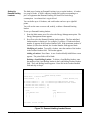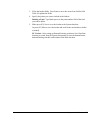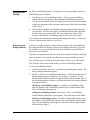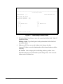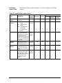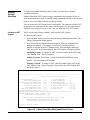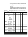
1
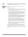
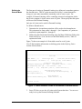
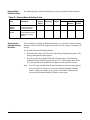
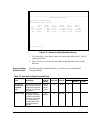
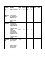
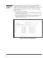
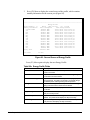
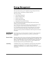
Energy Management
This section tells you how to use Companion’s energy management features:
Demand Limiting, Load Rolling, and Optimal Start/Stop.
This section includes:
●
About Energy Management
●
Defining Demand Limiting
●
Defining Load Rolling
●
Defining Optimal Start/Stop
●
Displaying an Energy Profile Summary
You’ll find information on displaying an Energy Profile in the Displaying
Summaries section of this manual.
You’ll find technical information about the energy management features in the
Metasys Companion Technical Manual under Software Data Sheets.
You’ll find additional information about energy management in the ASHRAE
Fundamentals manual and in the Johnson Controls Engineering Data Book.
This section assumes you know the information in the Getting Started section of
this manual.
About Energy
Management
By reducing energy costs and consumption, Companion’s energy management
features help you make your facility more cost effective and safe for the
environment.
Demand Limiting
Demand Limiting reduces energy costs by turning off designated equipment when
the amount of energy consumed by the facility approaches a specified target. The
purpose of Demand Limiting is to keep the demand for energy at any given time
below this target. This reduces energy costs because utility companies often
determine charges by the day’s peak demand for energy.
Load Rolling
Load Rolling reduces energy consumption by repeatedly turning off designated
equipment at specified intervals. For example, instead of running a fan
continuously, Load Rolling can save energy by turning the fan off for 15 minutes
of every hour.
Companion User’s Manual
149
Optimal
Start/Stop
Optimal Start/Stop (OST) reduces energy consumption by keeping a facility in its
unoccupied mode for as long as possible, and by putting it in its unoccupied mode
as soon as possible, without sacrificing comfort.
Defining
Demand
Limiting
To set up the Demand Limiting feature, you must have a System capability
password.
Demand Limiting works as follows:
●
●
●
●
●
You define an Accumulator (AC) point that will be used as a demand meter
to measure how much energy the facility is currently consuming. Companion
calls this consumption value the current demand.
You specify demand targets for different times of the day. This is the amount
of energy consumption that you do not want the facility to exceed. For
example, if you specify 1000 kW, you do not want more than 1000 kW to be
consumed during the demand interval. Typically, the demand interval is 15
minutes (as specified by the utility company).
You do not want the current demand to exceed the demand target. Therefore,
you specify the equipment that will be turned off if the current demand gets
close to the demand target. Turning off the equipment is called shedding.
The points you specify to be shed must be Binary Output points. These
points are called loads. You combine the loads in loadsets.
Demand Limiting compares the current demand to the demand target every
minute. If the current demand is too close to the demand target, Demand
Limiting sheds the designated equipment. By turning off equipment,
Demand Limiting prevents the current demand from exceeding the demand
target.
After equipment has been shed for a specified minimum time, Demand
Limiting returns control of the equipment to the ASCs or to other Companion
features. This is called releasing the loads.
If you make any changes to the Demand Limiting settings, these will not take
effect until the beginning of the next Demand Limiting cycle. For example, if
Demand limiting is currently shedding a loadset, and you delete the loadset, the
loadset will not be deleted until Demand Limiting completes its cycle by releasing
the loadset.
150 Companion User’s Manual
Defining the
Demand Meter
The first part of setting up Demand Limiting is to define an Accumulator point as
the demand meter. This AC point measures the facility’s current demand for
energy (or some other measurable commodity such as water or gas). For
example, if Demand Limiting will be controlling electrical consumption, define
the electric company’s electric meter as an AC point. Then specify that this point
will be used for Demand Limiting.
Only one AC point can be used for Demand Limiting.
To define a demand meter:
1.
Determine the Accumulator point that will be used as the demand meter.
This point must be from points 1 through 4. (In Companion, AC points are
restricted to point numbers 1 through 4.)
2.
Define the point for Demand Limiting using the Meter Definition fields in the
Point Add screen. (You can also use the Point Modify screen.) Table 22
explains the fields.
Figure 74 shows an example of a Point Add screen for an AC point.
(You’ll find complete information on defining points in the Defining Points
section of this manual.)
Operator Name:
S. Johnson
Thu Dec
1, 1994
14:00
---------------------------------------------------------------------------------Point Add
Point Number [ 1]
Software Type [AC]
Point Name [Electric Meter]
Network Address: N2 address [ 1]
Point Type [AC] Point Address [ 7]
Accumulator Point Definition
Consumption Engineering Units [KWH ]
Consumption Constant [ 1.000]
Rate Engineering Units [KW ]
Rate Constant [ 3600]
Low Limit [
0.0]
High Limit [ 2000.0]
Decimal Position [1]
Priority [Critical
]
Dial Sequence Number [1]
Alarm Reporting Definition
Alarm Message Used When Reporting [
Used For Demand Limiting [Yes]
F1 Cancel
1]
Meter Definition
Demand Interval [ 15]
F2 Save
Figure 74: Meter Definition Fields in Accumulator Point Add Screen
3.
Press (F2) Save to save the AC point to the System data base. You are now
ready to set up the Demand Limiting Schedule.
Companion User’s Manual
151
Demand Meter
Definition Fields
The following table explains the fields you will use to define the demand meter.
Table 22: Demand Meter Definition Fields
Field
Description
Options/
Range
Required?
Default
Used for
Demand
Limiting
Specifies the point that is
monitored for Demand
Limiting calculations.
Yes or No
Yes
No
Demand
Interval
Specifies what the utility
company defines as their
demand interval time in
minutes.
1 to 60
Yes
15
Setting Up the
Demand Limiting
Schedule
Numeric
Field Type
AlphaNumeric
Multiple
Choice
X
X
X
The second part of setting up Demand Limiting is to create the Demand Limiting
Schedule, which specifies the targets that you do not want energy consumption to
exceed.
To set up the Demand Limiting Schedule:
1.
From the Main menu, press E to select the Energy Management option. The
Energy Management menu appears.
2.
Press S to select the Schedule Demand Limiting option. The following
Demand Limiting Schedule appears (Figure 75). Note that the name of the
AC point defined as the demand meter appears at the top of the screen.
Note: If no AC point is defined for Demand Limiting, an error message appears
and you will not be allowed to access the Demand Limiting Schedule
screen. In this case, define an AC point for Demand Limiting and try
accessing the Demand Limiting Schedule screen again.
152 Companion User’s Manual
Operator Name:
S. Johnson
Thu Dec
1, 1994
14:00
---------------------------------------------------------------------------------Demand Limiting Schedule
Demand Meter: 1 Electric Meter
Current Demand Target: 1700 KW
Day
Mon-Fri
Sat
Sun
F1 Cancel
Start
On Peak
[07:00]
[07:00]
[08:00]
Demand
Target
[ 1800]
[ 1600]
[ 1400]
Start
Mid Peak
[12:00]
[00:00]
[00:00]
Demand
Start
Target
Off Peak
[
1900] [17:00]
[9999999] [17:00]
[
1900] [17:00]
Demand
Target
[
1700]
[9999999]
[9999999]
F2 Save
Figure 75: Demand Limiting Schedule Screen
Demand Limiting
Schedule Fields
3.
Fill in the fields. Press Enter to move the cursor from field to field. Table 23
explains the fields.
4.
Press (F2) Save to save the new Demand Limiting Schedule to the System
data base.
The following table explains the fields you will use to set up the Demand
Limiting Schedule.
Table 23: Demand Limiting Schedule Fields
Field
Description
Options/
Range
Required?
Default
Numeric
Start On Peak,
Start Mid Peak,
or Start Off
Peak
Specifies the starting times
for three different Demand
Limiting schedule periods.
Times are specified in 24hour format.
00:00 to
23:59 in
24-hour
format
Yes
00:00
X
Demand Target
Specifies a maximum
acceptable value (target)
for peak energy demand.
This “peak” is an average
in any interval during a
scheduled period. Rate
Engineering Units are
specified.
1 to
9999999
Yes
9999999
X
Field Type
AlphaMultiple
Numeric
Choice
Companion User’s Manual
153
Setting Up
Demand Limiting
Loadsets
The third part of setting up Demand Limiting is to set up the loadsets. A loadset
is a group of loads. A load is a Binary Output (BO) point corresponding to a
piece of equipment that Demand Limiting will turn off to limit energy
consumption. An exhaust fan is a typical load.
You can define up to 16 loadsets, and each loadset can have up to eight BO
points.
You will use the same screen to add, modify, or delete a Demand Limiting
loadset.
To set up a Demand Limiting loadset:
1.
From the Main menu, press E to select the Energy Management option. The
Energy Management menu appears.
2.
Press D to select the Demand Limiting loadset option. The first undefined
loadset number is displayed. For example, if you have 15 loadsets defined,
number 16 appears in the Loadset Number field. If the maximum number of
loadsets (16) has been defined, the Loadset Number field appears blank.
Modifying a Loadset: To modify a loadset, enter the number of the loadset
in the Loadset Number field. The loadset appears.
Adding a Loadset: Press Enter. A new Loadset Modify/Add/Delete screen
appears. The point fields will be blank.
Deleting a Load Rolling Loadset: To delete a Load Rolling loadset, enter
the number of the Load Rolling loadset in the Load Rolling Loadset Number
field. The Load Rolling loadset appears. Enter Del in the Loadset Enabled
field and skip to Step 4.
Operator Name:
S. Johnson
Thu Dec
1, 1994
14:00
---------------------------------------------------------------------------------Demand Limiting Loadset
Demand Meter: 1 Electric Meter
Loadset Number: [ 1]
Loadset Enabled [Yes]
If Current Demand Is
If Current Demand Is
Minimum Shed Time
Maximum Shed Time
Minimum Release Time
>= [ 95] % Of Demand Target THEN Shed This Loadset
<= [ 90] % Of Demand Target THEN Release This Loadset
(minutes) [ 15]
(minutes) [ 30]
(minutes) [ 15]
Point
[ 60] Exhaust Fan 1
[
]
[
]
[
]
F1 Cancel
F2 Save
Point
[ 61] Exhaust Fan 2
[
]
[
]
[
]
F3 More
Figure 76: Demand Limiting Loadset Screen
154 Companion User’s Manual
3.
Fill in the loadset fields. Press Enter to move the cursor from field to field.
Table 24 explains the fields.
4.
Specify the points you want to include in the loadset.
Deleting a Load: Type blank spaces in the point number field of the load
you want to delete.
5.
Either press (F2) Save to save the loadset to the System data base.
Or press (F3) More to save the loadset and scroll to the next loadset to define
or modify.
PC Version: After setting up Demand Limiting, perform a Save Data Base
function (accessed from the System Setup menu) to save the demand meter,
demand limiting schedule, and loadsets to the Disk data base.
Companion User’s Manual
155
Demand Limiting
Loadset Fields
The following table explains the fields you will use to set up the Demand
Limiting loadsets.
Table 24: Demand Limiting Loadset Fields
Field
Description
Loadset Number
Identifies a group of loads by
number.
Yes - available for DL
control
No - removed from DL
control
Del - inappropriate for DL
and therefore
removed as a DL
loadset
Specifies when DL sheds
this loadset relative to the
target consumption.
Loadset Enabled
If Current
Demand Is
> = [ ] % Of
Demand Target
THEN Shed This
Loadset
Options/
Range
Required?
Default
Numeric
1 to 16
Yes
N.A.
X
Yes, No, Del
Yes
Del
1 to 100
percent
Yes
N.A.
X
X
If Current
Demand Is
< =[ ] % Of
Demand Target
THEN Release
This Loadset
Specifies when DL releases
this loadset relative to the
target consumption.
1 to 100
percent, but
must be less
than the
value
specified
above.
Yes
N.A.
X
Minimum Shed
Time (minutes)
Specifies the shortest period
of time that this loadset can
be shed. Use this
parameter to avoid cycling
the loadset excessively.
1 to 240
minutes
Yes
N.A.
X
Maximum Shed
Time (minutes)
Specifies the maximum
period of time this loadset
can be kept from operating
before it must be released.
Use this parameter to force
DL to release loads before
their absence will be
significantly missed.
1 to 240
minutes, but
must be
greater than
minimum
shed time
value
specified
above.
Yes
N.A.
X
Minimum
Release Time
(minutes)
Specifies the shortest period
of time that this loadset must
remain released. Use this
parameter to allow loads to
have some functional impact
before being shed again by
DL.
1 to 240
minutes
Yes
N.A.
X
Point
At least 1 and as many as
8 points can be specified for
each loadset. Each point
specifies a particular load.
Entries must be defined, BO
software points that are
unique to that loadset.
Any defined
BO point
Yes
N.A.
X
156 Companion User’s Manual
Field Type
AlphaMultiple
Numeric
Choice
X
Defining Load
Rolling
To define Load Rolling loadsets, you must have a System capability password.
Load Rolling works as follows:
●
●
You define up to 16 Load Rolling loadsets. These are groups of Binary
Output points corresponding to the equipment Load Rolling will turn off.
You specify the amount of time the equipment will be turned off, the amount
of time the equipment will be released, and the time of day that Load rolling
will be active.
If the loadset is enabled, Load Rolling turns the equipment off for the time
you specified. After the time elapses, Load Rolling releases the equipment
for the release time you specified. After the release time elapses, if the
loadset is still enabled, Load Rolling starts the off/release cycle again.
You’ll find technical information about Load Rolling in the Metasys Companion
Technical Manual under Software Data Sheets.
Setting Up Load
Rolling Loadsets
A loadset is a group of loads. Loads are Binary Output points corresponding to
the equipment that Load Rolling will turn off according to the time you specify.
For example, you can specify that all loads in the loadset be turned off for ten
minutes of every half hour.
Typically, the equipment specified as a load can be turned off without sacrificing
safety or comfort. For example, an exhaust fan is a good candidate for a load.
You can define up to 16 loadsets, and each loadset can have up to 8 BO points.
You’ll use the same screen to add, modify, or delete Load Rolling loadsets.
To set up Load Rolling loadsets:
1.
From the Main menu, press E to select the Energy Management option. The
Energy Management menu appears.
2.
Press L to select the Load Rolling loadset option. The first undefined Load
Rolling loadset number is displayed. For example, if you have 15 Load
Rolling loadsets defined, number 16 appears in the Loadset Number field. If
the maximum number of loadsets (16) has been defined, the Loadset Number
field appears blank.
Modifying a Load Rolling Loadset: To modify a Load Rolling loadset,
enter the number of the Load Rolling loadset in the Loadset Number field.
The Load Rolling loadset appears.
Adding a Load Rolling Loadset: Press Enter. A new Load Rolling
Loadset Modify/Add/Delete screen appears. The point fields will be blank.
Deleting a Load Rolling Loadset: To delete a Load Rolling loadset, enter
the number of the Load Rolling loadset in the Load Rolling Loadset Number
field. The Load Rolling loadset appears. Enter Del in the Loadset Enabled
field and skip to Step 4.
Companion User’s Manual
157
Operator Name:
S. Johnson
Thu Dec
1, 1994
14:00
---------------------------------------------------------------------------------Load Rolling Loadset
Loadset Number:
[
1]
Loadset Enabled [Yes]
From [07:00] To [17:30]
Off Time (minutes) [15]
Release Time (minutes) [45]
Point
[ 61] Exhaust Fan 3
[
]
[
]
[
]
F1 Cancel
F2 Save
Point
[ 63] Exhaust Fan 4
[
]
[
]
[
]
F3 More
Figure 77: Load Rolling Loadset Screen
3.
Fill in the fields. Press Enter to move the cursor from field to field. Table 25
explains the fields
Deleting a Load: Type blank spaces in the point number field of the load
you want to delete.
4.
Either press (F2) Save to save the loadset to the System data base.
Or press (F3) More to save the loadset and scroll to the next loadset to define
or modify.
PC Version: After setting up the Load Rolling loadsets, perform a Save
Data Base function (accessed from the System Setup menu). This saves the
loadsets to the Disk data base.
158 Companion User’s Manual
Load Rolling
Loadset Fields
The following table explains the fields you will use to define Load Rolling
loadsets.
Table 25: Load Rolling Loadset Fields
Field
Description
Loadset
Number
Identifies a group of loads
by number.
Loadset
Enabled
Yes - available for LR
control
Options/
Range
Required?
Default
Numeric
1 to 16
Yes
N.A.
X
Yes, No,
and Del
Yes
Del
Field Type
AlphaMultiple
Numeric
Choice
X
X
No - removed from LR
control
Del - inappropriate for LR
and therefore
removed as a LR
loadset
From [ ] To [ ]
Specifies the time period
that LR will be active for
this loadset. When active,
LR cycles the loadset
between shed and release
states. Use this parameter
to activate LR according to
a schedule.
00:00 to
23:59 in
24-hour
format
Yes
00:00
X
Off Time
(minutes)
Specifies how long the
loadset will be shed during
each shed/release cycle.
1 to 240
minutes
Yes
N.A.
X
Release Time
minutes)
Specifies how long the
loadset will be released
during each shed/release
cycle.
1 to 240
minutes
Yes
N.A.
X
Point
At least 1 and as many as
8 points can be specified
for each loadset. Each
point specifies a particular
load. Entries must be
defined, BO software
points.
Any
defined
BO point
Yes
N.A.
X
Companion User’s Manual
159
To define the Optimal Start/Stop (OST) feature, you must have a System
capability password.
Defining
Optimal
Start/Stop
Optimal Start/Stop (OST) reduces energy consumption by keeping a facility in
unoccupied mode for as long as possible, and by putting the facility in unoccupied
mode as early as possible, without sacrificing comfort.
You can create one OST system for each air handler. The points involved in OST
do not need to be controlled by the same controller; however, all points must be
online in order for the process to work. You can define up to 30 OST systems.
Creating an OST
System
You’ll use the same screen to modify, add, or delete OST systems.
To create an OST system:
1.
From the Main menu, press E to select the Energy Management option. The
Energy Management menu appears.
2.
Press O to select the Optimal Start/Stop option. The first undefined OST
number is displayed. For example, if you have 29 systems defined,
number 30 appears in the OST Number field. If the maximum number of
OST processes (30) has been defined, the OST Number field appears blank.
Modifying System: To modify an OST, enter the number of the OST in the
OST Number field. The OST appears.
Adding a System: Press Enter. A new OST Modify/Add/Delete screen
appears. The point fields will be blank.
Deleting a System: To delete an OST, enter the number of the OST in the
OST Number field. The OST appears. Enter Del in the OST Enabled field
and skip to Step 4.
Operator Name:
S. Johnson
Thu Dec
1, 1994
14:00
-----------------------------------------------------------------------------------------Optimal Start/Stop Modify/Add/Delete
OST System Number [ 5]
OST Enabled [Yes]
Zone Occupied Mode point
[ 31]
31 Flr1 OCCUPIED Md
No
Zone Warmup/Cooldown Mode Point
[ 50]
50 Flr1 WRM/CLDN Md
On
Heating Set Point Point
[ 42]
42 AHU1 Heating Setpoint 70.0
Cooling Set Point Point
[ 78]
78 AHU1 COOLING Setpoint 74.0
Zone Temperature Point
[ 25]
25 Flr1 Zone Temp
74.0
Outdoor Air Temperature Point
[ 22]
22 AHU1 OA Temp
79.2
Building Heating/Cooling Constant [ 3]
Building Design Temperatures: Heating (degrees)[-5] Cooling (degrees) [95]
Maximum Preheat/Precool Time (minutes) [ 30]
Maximum Prestop Time (minutes) [ 15]
Scheduled Zone Occupied Mode Start/Stop Time
Computed Warmup/Cooldown Mode Start Time
Computed Zone Occupied Zone Stop Time
F1 Cancel
F2 Save
Deg
Deg
Deg
Deg
06:30 / 18:00
06:00
17:45
F3 More
Figure 78: Optimal Start/Stop Modify/Add/Delete Screen
160 Companion User’s Manual
3.
Fill in the OST fields. Press Enter to move the cursor from field to field.
Table 26 explains all the fields in the OST Modify/Add/Delete screen.
4.
Either press (F2) Save to save the new OST system to the System data base.
Or press (F3) More to save the system and scroll to the next OST system to
add or modify.
PC Version: Remember to save the new system to the Disk data base by
performing a Save Data Base function (accessed from the System Setup
menu).
OST Definition
Fields
The following tables explain the fields you will use to set up OST systems.
Table 26a: OST Definition Fields
Field
Description
OST System
Number
Identifies the zone
controlled by this OST
process.
OST Enabled
Shows:
Yes - system available for
OST control
Options/
Range
Required?
Default
Numeric
1 to 30
Yes
N.A.
X
Yes, No,
and Del
Yes
Del
Field Type
AlphaMultiple
Numeric
Choice
X
X
No - system removed
from OST control
Del - inappropriate for
OST and therefore
deleted
Zone Occupied
Mode Point
Identifies the BO point
used to determine if a
zone is occupied or
vacant. This BO point
must also be specified on
a weekly schedule.
Any
defined
BO point
Yes
N.A.
X
Zone Warmup/
Cooldown Mode
Point
Identifies the BO point
used to determine if the
zone is presently in a
warmup/cooldown mode
of operation.
Any
defined
BO point
Yes
N.A.
X
Heating Set
Point Point
Identifies the point used to
define the heating set
point for the zone.
Any
defined AI
or AO
point
Yes
N.A.
X
Any
defined AI
or AO
point
Yes
N.A.
X
Can be the same as the
Cooling Set Point.
Cooling Set
Point Point
Identifies the point used to
define the cooling set point
for the zone.
Can be the same as the
Heating Set Point.
Continued on next page . . .
Companion User’s Manual
161
Field (Cont.)
Description
Options/
Range
Required?
Default
Numeric
Zone
Temperature
Point
Identifies the point used to
determine the actual zone
temperature.
Any
defined
AI point
Yes
N.A.
X
Outdoor Air
Temperature
Point
Identifies the point used to
determine the actual
outside air temperature.
Any
defined
AI point
Yes
N.A.
X
Building
Heating/Cooling
Constant
Provides an initial value for
a constant used in the
OST time calculation. It is
adapted by the system
once per day without
operator intervention. This
value is specified as
minutes per degrees
squared.
1 to 999
Yes
50
X
Building Design
Temperatures
Heating (degrees):
-30 to 90 °F
Yes
-5
X
0 to 120 °F
Yes
95
X
Indicates the lowest
outside temperature at
which the heating system
will maintain zone
comfort in the heating
mode. Values are
obtained using ASHRAE
manuals.
Cooling (degrees):
Indicates the highest
outside temperature at
which the cooling system
will maintain zone
comfort in the cooling
mode. Values are
obtained using ASHRAE
manuals.
Maximum
Preheat/Precool
Time
Indicates the maximum
period of time required to
bring the zone up to
occupancy set point
temperature under the
worst conditions.
5 to 240
minutes
Yes
120
X
Maximum
Prestop Time
Indicates the earliest the
heating/cooling system
can be shut down and still
maintain the occupied
zone temperature until
entering the vacant mode.
5 to 60
minutes
Yes
30
X
162 Companion User’s Manual
Field Type
AlphaMultiple
Numeric
Choice
Displaying an
Energy Profile
Summary
The Energy Profile Summary displays detailed information about the energy
consumption of your facility. The summary can include up to four energy
profiles. Each profile displays data for one Accumulator point. (There can be up
to four Accumulator points defined for each facility.) Table 26b explains the
Energy Profile fields.
To display an Energy Profile Summary:
1.
From the Main menu, press E to select the Energy Management option. The
Energy Management menu appears.
2.
Press E to select the Energy Profile Summary option. The first screen of the
Energy Profile appears (Figure 79). The first screen displays daily
information for the current week.
Operator Name:
S. Johnson
Thu Dec
1, 1994
14:00
---------------------------------------------------------------------------------Energy Profile
Profile Number [ 1]
Meter: 1 AHU O AC B17
Cr1 1645 KW
Current Information
Instantaneous Demand: 1645 KW
Current Demand Target: 1900 KW
Average Demand:
1516 KW
Demand Interval:
15 Min
Daily Information
Today
Sun
Mon
Tue
Wed
Thu
Fri
Sat
F1 Cancel
Total Consumption
10050.0 KWH
17380.0 KWH
33504.0 KWH
30310.0 KWH
31490.0 KWH
31489.0 KWH
31469.0 KWH
33290.0 KWH
Peak Average Demand
1002.1 KW At 12:01
1224.3 KW At 13:16
1896.4 KW At 02:19
1763.6 KW At 04:15
1812.6 KW At 13:14
1811.0 KW At 13:58
1887.0 KW At 14:03
1473.0 KW At 14:13
F3 More
Figure 79: First Screen of Energy Profile
Companion User’s Manual
163
3.
Press (F3) More to display the second screen of the profile, which contains
monthly information for the current year (Figure 80).
Operator Name:
S. Johnson
Thu Dec
1, 1994
14:00
---------------------------------------------------------------------------------Energy Profile
Profile Number [ 1]
Meter: 1 AHU O AC B17
Cr1 76.9 KW
Monthly Information
Total Consumption
Peak Average Demand
Current Month
101800.4 KWH
1002.1 KW At 12:01 On Dec 01
Jan
590300.0 KWH
1713.0 KW At 13:02 On Jan 08
Feb
663410.1 KWH
1809.2 KW At 12:56 On Feb 12
Mar
603180.0 KWH
1500.4 KW At 13:01 On Mar 11
Apr
690100.0 KWH
1645.9 KW At 12:23 On Apr 15
May
790100.2 KWH
1660.8 KW At 13:34 On May 01
Jun
823100.0 KWH
1500.1 KW At 13:53 On Jun 11
Jul
903550.0 KWH
1431.3 KW At 12:23 On Jul 08
Aug
873451.2 KWH
1812.1 KW At 13:20 On Aug 05
Sep
863410.2 KWH
1781.3 KW At 12:30 On Sep 08
Oct
821810.5 KWH
1911.9 KW At 12:10 On Oct 15
Nov
995510.3 KWH
2077.7 KW At 13:48 On Nov 12
Dec
101800.4 KWH
802.1 KW At 12:01 On Dec 01
Yearly Total
8719722.9 KWH
F1 Cancel
F3 More
Figure 80: Second Screen of Energy Profile
Press (F3) More again to display the next Energy Profile.
Table 26b: Energy Profile Fields
Field
Description
Meter
Specifies the hardware point in the system to which the demand
meter is connected.
Instantaneous Demand
Specifies the rate of consumption or amount of energy being
consumed in the current minute.
Current Demand Target
Specifies the current maximum acceptable value (target) for peak
energy demand. The peak is an average in any interval during a
scheduled period. Rate Engineering Units are specified.
Average Demand
Specifies the average rate of consumption or amount of energy
being consumed over the demand interval defined.
Demand Interval
Specifies what the utility company defines as their demand interval
in minutes.
Daily / Monthly Information
Specifies the total consumption and peak average demand in both
daily and monthly formats.
Total Consumption
Specifies the total amount of energy consumed since the period
started. The periods for this display are daily and monthly.
Peak Average Demand
Specifies the highest average demand detected over the period.
The periods for this display are daily and monthly.
164 Companion User’s Manual