1
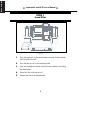
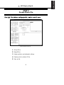
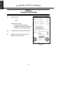
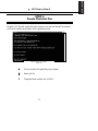
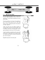
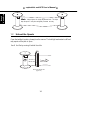
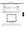
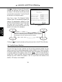
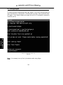
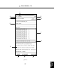
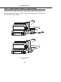
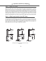
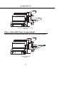
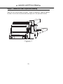
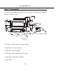
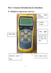
VX4000 Automated Film Drive (AFD) and vxphotolist USERS MANUAL © Vexcel Imaging Corporation. All rights reserved. Printed in the United States of America. For assistance contact Vexcel Imaging Corporation: 3131 Indian Rd Boulder, Colorado 80301 USA (303) 440 - 9790 [email protected] Manual Conventions 1. Action Button Text: This is text on a button that, when clicked with the mouse, will generally cause the software to perform a task, open a different window, or allow the user to choose a parameter (such as “negative” or “diapositive”). All such text will appear in bold, such as Setup... in the AFD Main Window. 2. “User interface descriptive text”: This is text that labels a part of the user interface, such as “Roll Type” in the AFD Main Window. Clicking on this text, which will be shown in quotes, will have no effect. 3. ‘Menu item text’: Single quotes around text signifies text that appears either on the menu bar itself or an option when an item on the menu bar is selected. The quotes signal to the user that this is the text that should be chosen to achieve the desired effect, such as opening a window. For example, select ‘Open .phl file’ to gain access to the Open Photo List File Window. 4. Input field: Fields identifed by descriptive text, such as “Roll Type”, that can be clicked in and edited by the user. ii vxphotolist & Automated Film Drive because machines don’t need to go home at night.... The Automated Film Drive (AFD) was designed to increase productivity and decrease labor costs by providing automatic and unattended film scanning. AFD includes the following features: • • • • • Film speed - up to 200 feet per minute. Accomodates spools up to 1,000 feet, 70 mm to 9.5 inches. Spring-loaded universal spindle tips automatically adjust to fit spools. Adjustable spindle arm posts make film spool interchange fast and easy. Fully programmable - scans film in sequences defined by the user. vxphotolist was developed to assist the user by simplifying the unattended scanning process. Through vxphotolist the user defines which frames will be scanned and how. AFD and vxphotolist are valuable tools for the VX4000 series of scanners. iii ||||| ,,,,, yyyyy zzzzz {{{{{ ,,,,, yyyyy zzzzz {{{{{ ||||| ,,,,, yyyyy zzzzz {{{{{ ||||| ,,,,, yyyyy zzzzz {{{{{ ||||| ,,,,, yyyyy zzzzz {{{{{ ||||| iv TABLE OF CONTENTS Manual Conventions Introduction . . . . . . User’s Notes . . . . . . Table of Contents . . . . . . . . . . . . . . . . . . . . . . . . . . . . . . . . . . . . . . System Configuration and Connectivity Step 2 Create .ph File .ii .iii .iv .1 2.1 2.2 2.3 2.4 2.5 2.6 2.7 3 System Configuration . . . . . . . . . Controller Computer Connectivity System Connectivity . . . . . . . . . . AFD Components . . . . . . . . . . . . . . . . . . . . . . . . . . . . .3 .4 .5 .6 Step 3 AFD Setup AFD and vxphotolist: Step by Step . . . . . . . . . . . . . . .7 AFD Step by Step . . . . . . . Step 1 Load Film . . . . . . . Step 2 Create Photo File . Step 3 AFD Setup . . . . . . Step 4 Create Photolist File Step 5 Execute vxphotolist Step 1 Load Film . . . . . . . . . . . . . . . . . . . . . . . . . . . . . . . . . . . . . . . . . . . . . . . . . . . . . . .ph file overview . . . . Establish an ROI . . . . Verify current settings Name ROI . . . . . . . . . Adjust Radiometry . . . Digitize Point(s) . . . . . Save .ph file . . . . . . . 17 . . . . . . . . . . . . . . . . . . . . . . . . . . . . . . . . . . . . . . . . . . . . . . . . . . . . . . . . . . . . . . . . . . . . . . .17 .17 .18 .19 .19 .20 .20 21 3.1 AFD Main Window & Setup Flow . . .21 AFD Setup Flowchart . . . . . . . . . . .22 3.2 Roll Setup Window . . . . . . . . . . . . .23 3.3 Default Mounting Parameters Window . . . . . . . . . . . . . . . . . . . . . . . . .25 3.4 Frame Parameters Window . . . . . .26 3.5 Frame Mounting Window . . . . . . . . .28 3.6 Completing AFD Setup . . . . . . . . . .29 3.7 Mounting Parameters Window . . . . .30 3.8 Verify Frame Numbers . . . . . . . . . .32 .7 .8 .9 .10 .11 .12 Step 4 Create .phl File 13 1.1 Mount film rolls . . . . . . . . . . . . . . . .13 1.2 Unload the spools . . . . . . . . . . . . . .14 1.3 Reel the film . . . . . . . . . . . . . . . . . .15 4.1 4.2 4.3 4.4 4.5 1 33 .phl File Overview . . . . . . . . . . . . . .33 .phl File Configuration . . . . . . . . . . .33 Using phlgen . . . . . . . . . . . . . . . . . .34 Creating a .phl file . . . . . . . . . . . . . .35 Additional features of phlgen . . . . . .38 Step 5 Execute vxphotolist Appendices 39 5.1 vxphotolist Overview . . . . . . . . . . . .39 5.2 vxphotolist Window . . . . . . . . . . . . .39 5.3 Photolist File Name . . . . . . . . . . . . .40 5.4 Program Status . . . . . . . . . . . . . . . .40 5.5 Append Frame Number to File Name . . . . . . . . . . . . . . . . . . . . . . . . . .40 5.6 Overwriting an Existing Data File . . .41 5.7 Selecting Specific .ph Files and Frames for scanning . . . . . . . . . . . . . . .42 5.8 Starting the scan . . . . . . . . . . . . . . .42 User Interface 63 Appendix I Creating .phl File using a Text Editor . . .63 User’s Notes . . . . . . . . . . . . . . . . . . . . .66 Appendix II AFD Hardware, Components and Setup . . . . . . . . . . . . . . . . . . . . . . . . . .67 User’s Notes . . . . . . . . . . . . . . . . . . . . .74 Appendix III Fiducial Mode Setup . . . . . . . . . . . . . . .75 43 Index AFD Main Window . . . . . . . . . . . . . . . .43 Roll Setup Window . . . . . . . . . . . . . . . .46 Frame Parameters Window . . . . . . . . . .50 Frame Mounting Window . . . . . . . . . . .52 Default Mounting Window . . . . . . . . . . .54 Mounting Parameters Window . . . . . . . .55 vxphotolist Window . . . . . . . . . . . . . . . .57 User’s Notes . . . . . . . . . . . . . . . . . . . . .62 2 79 ▲ Configuration and Connectivity ▼ System Configuration The VX4000 Scanning system with AFD (diagram shown below) is configured with a scanner pc controller, image monitor, controller monitor, scanner, AFD controller and two AFD towers. E t h e r n e t Left AFD Tower Right AFD Tower VX4000 Scanner Image Monitor Scanner Controller Controller Monitor AFD Controller Ethernet A standard Ethernet network that connects the Scanner Controller to remote network devices (ie; pc, workstation, server). Scanner Controller The component that houses the controlling hardware and software for the VX4000 scanner and the windows NT based formatter. Image Monitor The monitor which displays the live camera view. Controller Monitor The monitor which displays the Window NT, vxscan, and vxphotolist User Interface. AFD Controller The component that houses the controlling hardware for the AFD. AFD Towers The devices that hold the film spools during the scanning process. 3 • vxphotolist and AFD User’s Manual • Controller Computer Connectivity power cord Serial Cable - Com2 to Scanner Serial Cable - Com1 to AFD Controller ( if applicable) VGA Cable - Video card to Interface Monitor Digital Cable - ITI card to Scanner VGA Cable - ITI card to Image Monitor Network Cable Controller Computer Connectivity (Figure 1) 4 ▲ Configuration and Connectivity ▼ System Connectivity System connectivity (Figure 2) 5 • vxphotolist and AFD User’s Manual • AFD Components The AFD Towers: Height adjustment knob Spindle arm • The left and right towers may be used interchangeably for supply or take up. Upper mounting bracket Crank handle • The spool pins ensure the roll is held securely in place during the scanning process. Film roller Spool pins Spindle arm post • The spindle arms swing back and forth, as well as up and down. Lower mounting bracket • The towers are held securely to the VX 4000 scanner by the upper and lower mounting brackets. Right AFD Tower (Figure 3) AFD Controller : power indicator • The AFD controller not only supplies power, it also houses the controlilng electronics used to run the AFD. AFD controller (Figure 4) 6 STEP BY AFD STEP ▲ AFD Step by Step ▼ & vxphotolist Step By Step ........ AFD Main Window (Figure 6) vxphotolist Window (Figure 5) 1 Load Film. 2 Create Photo File. 3 AFD Setup. 4 Create Photolist File. 5 Execute vxphotolist. 7 STEP BY STEP • vxphotolist and AFD User’s Manual • STEP 1 Load Film VX4000 scanning system with Automated Film Drive (Figure 7) 1 Place the supply roll on the desired tower, ensuring the film unloads from the back of the roll. 2 Place the take up roll on the remaining tower. 3 Open the backlight and thread the film through, emulsion side facing the reseau plate. 4 Secure the film to the take up roll. 5 Advance the film to the desired frame. 8 STEP BY STEP 2 Create Photo File Photo (.ph) files, which are used by vxphotolist, must be created in vxscan. vxscan Main Window (Figure 8) 1 Set up ROI(s). 2 Name ROI(s). 3 Adjust resolution and radiometric settings. 4 Digitize point for relative ROI(s). 5 Save .ph file. 9 STEP ▲ AFD Step by Step ▼ STEP BY STEP • vxphotolist and AFD User’s Manual • STEP 3 Complete AFD Setup 1 Select Roll Type.. - or Create New Roll Type.. • Complete Roll Setup Window. • Complete Frame Parameters Window. • Complete Frame Mounting Window. 2 Complete Mounting Parameters Window.. 3 Set Frame # in “Frame” input field and update current film position. AFD Main Window (Figure 9) 10 STEP BY STEP 4 Create Photolist File Photolist (.phl) files tell vxphotolist which frames to scan and how they will be scanned. .phl files are created using phlgen, the file generating script. DOS/Console box during phlgen (Figure 10) 1 Run the photolist file generating script (phlgen). 2 Name .phl file. 3 Designate frame numbers and .ph file(s). 11 STEP ▲ AFD Step by Step ▼ STEP BY STEP • vxphotolist and AFD User’s Manual • STEP 5 Execute vxphotolist 1 Open .phl file. 2 Select frame number, overwrite, and .ph file options. 3 Start scanning. vxphotolist Window (Figure 11) 12 ▲ Step 1 - Load Film ▼ 1.1 Mount Film Rolls Turn the height adjustment knob to loosen the spindle arm. This will allow the spindle arm to move up and down. Move the spindle arm to the top of the spindle arm post. Once the arm reaches the top it will swing freely, and ‘open’, allowing the spool to be placed on the tower. (Figure 12) Lower the spool onto the bottom spindle tip ensuring that the film will unroll from the back, with the emulsion side facing the reseau plate. Turn the spool and listen for the pins to “click” into place. Spindle arm ‘open’ (Figure 12) Lower the spindle arm assembly onto the spool until it closes over, or drops down onto, the spool. (Figure 13) Using the crank handle, turn the roll until the top pins “click” into place. Repeat this process for the other spool. Spindle arm ‘closed’ (Figure 13) 13 STEP 1 LOAD FILM Step 1 - Load Film STEP 1 LOAD FILM • vxphotolist and AFD User’s Manual • Hint: Always tighten the height adjustment knob. This helps keep the spool in one place and greatly increases accuracy. 1.2 Unload the Spools Open the backlight, pushing it away from the scanner. The backlight mechanism is stiff and may require a firm push to open. Unroll the film by running it behind the roller. Film running behind roller (Figure 14) 14 ▲ Step 1 - Load Film ▼ Be sure the film loads and unloads from the back of the roll and not the front. STEP 1 LOAD FILM Film unloading from back - correct (Figure 15) Film unloading from front - incorrect (Figure 16) Thread the film between the backlight and the reseau plate. Wrap the film around the take-up reel using a friction wrap. A friction wrap simply requires the user to wrap the film around itself several times until the film is securely held in place. 1.3 Reel the Film Use the crank handle to reel the film manually. To set the handle in an upright position, simply pull it up until it ‘snaps’ into place. To return it to the down position, first pull up on the handle then set it down. Handle in the ‘down’ position (Figure 18) Handle in the ‘up’ position (Figure 17) 15 STEP 1 LOAD FILM • vxphotolist and AFD User’s Manual • NOTE: Tension will occur if the film is reeled more than ten frames making it difficult to continue reeling. Pausing momentarily will ease the tension and allow the film to be advanced Hint: The towers were designed to operate with the crank handles down. For best results, always return the handles to the down position. 16 ▲ Step 2 - Create .ph File ▼ Step 2 - Create .ph File .ph files, which are created in vxscan, contain the following information: Placement of ROI(s) Radiometry of the ROI(s) Resolution Location of any point(s) digitized through the Acquire Points function. Once saved, .ph files are combined with frame numbers to create the .phl files required by vxphotolist. This section will describe briefly the steps necessary to create a .ph file. More detailed instructions and definitions can be found in the VX4000 User’s Manual. For best results it is recommended the VX4000 User’s Manual be read thoroughly prior to this manual. 2.2 Establish an ROI The first step in creating a .ph file is to establish the ROI(s). Move the camera to the top left corner of the image centered in the backplane. Place the pointer on the top left corner of the red ROI box and move it until it is positioned where desired. Click on the bottom right corner to stretch the ROI to the desired size. - or - If the size of the ROI is already known, simply enter the dimensions in the width and height fields (for instance 230 mm x 230 mm for full frame scan). 17 STEP 2 CREATE .PH FILE 2.1 .ph File Overview • vxphotolist and AFD User’s Manual • 2 STEP 2 CREATE .PH FILE 1 3 4 vxscan main menu (Figure 19) 2.3 Verify Current ROI Settings Prior to naming the ROI, the user should verify the following ROI settings: 1. Select desired format (ie, Tiff, BSF, No Format, etc.) 2. Designate the orientation of the scan with respect to the source image (Normal/Mirrored). Must always be set to relative. 3. 4. Designate formatter (Local/Remote). Note: The above configuration is an example, all settings can vary except relative. 18 ▲ Step 2 - Create .ph File ▼ 2.4 Name ROI Hint: An underscore placed after the name can make it easier to read if the frame number is going to be appended to the file name. For example: d:\scans\bldr_ (see section 5.5 on page 40) 2.5 Adjust Radiometry Move the camera to the brightest area in the image. Enter the resolution that will be used on the scan in the “Resolution” input field in the lower left hand side of the vxscan main screen. Click on the Histogram button to bring up a histogram where the gray level is represented horizontally and the number of pixels is represented vertically. Use the slide bars on the right hand side to adjust the brightness. If desired, the gray level settings can be edited manually by clicking within the brightness or contrast fields. The histogram will be automatically updated. Move the camera to the darkest region of the image so that the Contrast can be adjusted. Use the slide bar on the left hand side of the histogram to make any necessary adjustments. Once satisfied with the settings, close the Histogram and select the Apply to ROI button so that the setting will be applied to the newly created ROI. For additional assistance, refer to the VX4000 User’s Manual. 19 STEP 2 CREATE .PH FILE Click in the “ROI” input field. The Prompt_popup Window will appear automatically. Use the delete or backspace keys to delete any existing name that may already be in the window. Type an absolute path name for the Region of Interest. (eg: d:\scans\bldr) The path designated when naming the ROI indicates where images will be stored when the scanning process has been completed. • vxphotolist and AFD User’s Manual • STEP 2 CREATE .PH FILE 2.6 Digitize Point(s) From the Edit menu, select ‘Acquire Points’. This brings up the Acquire Point Window. Ensure Template has been selected. Move the camera to the upper left corner point of the ROI. Place the mouse pointer over the desired point and digitize it by clicking on the point using the left mouse button. An asterisk will appear next to the point name in the Acquire Points Window. When scanning in edge mode, the user must digitize at least one point, when scanning in Fiducial mode, at least four fiducials must be digitized. Once satisfied, click on OK. Note: This process must be performed while in Accurate Mode. 2.7 Save .ph File From the Menu Bar, select File, then ‘Save as’. Type the desired name in the “Selection” input field and click on OK to complete the process. Photo files are denoted by a .ph extension. Hint: It is often convenient to assign a name that pertains to the job that is being performed; customer name, roll number, or location name for example. 20 ▲ Step 3 - AFD Setup ▼ STEP 3 AFD SETUP 3.1 AFD Main Window and Setup Flow The AFD Main Window allows the user to give the application all of the physical information about the roll of film to be scanned. This information is broken down into Three categories: Roll Setup, Frame Setup, and Frame Finding. Frame Setup information includes: Frame Finding information includes: Spindle diameters Film thickness Frame spacing Default offset Default speed Frame type Accuracy Frame size Exposure type Camera database file Edge region locations (up to 16 per image) Scanner resolution Scanner brightness Scanner contrast Rotation Mirrored or normal Although the AFD Main Window appears when vxphotolist is started, it is suggested that the AFD setup be performed while in vxscan. While completing the AFD setup it is sometimes necessary to adjust the radiometry. If vxscan is open these adjustments can be made immediately. Otherwise, the user would have to exit vxphotolist, open vxscan, and then return to vxphotolist. To access the AFD Main Window from vxscan select ‘Options’ from the vxscan menu bar. If ‘Automated Film Roll...’ is grayed out, select ‘Set Preferences’. In the Set Preferences Window, click on the “Use Film Drive” check box. Then, back under ‘Options’, choose “Automated Roll...”. 21 AFD Main Window (Figure 20) STEP 3 AFD SETUP Roll Setup information includes: • vxphotolist and AFD User’s Manual STEP 3 AFD SETUP AFD Setup Flowchart (Figure 21) 22 • ▲ Step 3 - AFD Setup ▼ 3.2 Roll Setup Window If the desired roll type already exists, enter the name in the “Roll Type:” input field on the AFD Main Window. An existing roll type can also be selected from the input field directly below the “Roll Type” input field by clicking on the desired name. Once a roll type is selected, the Mounting Parameters Window automatically appears (refer to section 3.6) and the user may proceed. If a new roll type must be created, the Roll Setup, Frame Parameters, and Frame Mounting Windows will need to be completed before proceeding on to the Mounting Parameters Window.. Click on the Setup button to bring up the Roll Setup Window (Figure 22). STEP 3 AFD SETUP The default values in the “Left Spindle Diam(mm):” and “Right Spindle Diam(mm):” are generally good for any photography spindle and need not be changed. “Film Thickness” can be measured by the user after a Roll Type has been selected (see section 3.6) Frame Spacing refers to the distance from the left edge of one image to the left edge of the next image. The user should measure this distance and fill in the “Frame Spacing (mm)” input field. These distances can be measured manually by placing a measuring stick or tape in front of the reseau glass, or digitally using vxscan. Edge of Reseau Plate Film Frame Spacing (Figure 23) 23 Roll Setup Window (Figure 22) • vxphotolist and AFD User’s Manual • STEP 3 AFD SETUP To measure digitally, first set two images in the backplane. Then, in vxscan, place the camera so that the left edge of the left image is visible on the image monitor. Select ‘Options’ from the Menu Bar and click on ‘Set Preferences’. In the Preferences Window, click on “Size in mm/inches”. Draw an ROI in the vxscan Main Window that starts at the left edge of the left image and stretch it to the left edge of a neighboring image. Use the image monitor to ensure that the ROI is accurately placed on the edges of the images. The top middle section of the vxscan Main Window will contain information on the width and height of the ROI created. Use the “Width” value given for frame spacing. Edge of Reseau Plate “Default Offset” refers to the distance from the left edge of the backplane to the left edge of the target image. The default value, 150 mm, assumes the user has placed the target image in the center of the backplane. Default Offset (Figure 24) The “Default Speed:” input field is used to designate the speed at which AFD will automatically move the film in millimeters per second. The speed can be adjusted here, or later from the AFD Main window. “Accuracy” refers to the method that will be used to find the frames during the scanning process. Clicking on the button to the right of this option brings up three options: “Approximate”, “Edge of Film”, and “Fiducials”. The degree of accuracy varies with each method. • The Approximate mode is the fastest of the three but has the lowest level of accuracy. • If Edge of Film mode is selected, AFD will use the contrast between the developed and undeveloped film as a means for finding the edges of the frame. As the film advances, the application will automatically check the film to make sure that the edges are where they are supposed to be. The values used to advance the film will 24 ▲ Step 3 - AFD Setup ▼ be adjusted throughout the scanning process to take into consideration any discrepancies. This method is the most frequently used. • Fiducial mode is the most accurate frame finding method. The higher accuracy requires additional time. 3.3 Default Mounting Parameters Window Clicking on the Default Mounting button will bring up the Default Mounting Parameters Window as shown in Figure 25. Through this window the user is able to define default values for the left and right spindle diameters, as well as the “Frame Advance Direction”. Frame Advance Direction will be discussed in more detail in section 3.6, Mounting Parameters. STEP 3 AFD SETUP Default Mounting Parameter Window (Figure 25) The next step in the setup process is to complete the Frame Setup Window. Click on Frame Setup... to bring up the Frame Parameters Window. 25 • vxphotolist and AFD User’s Manual • 3.4 Frame Parameters Window If an existing frame was selected in the Roll Setup Window the Frame Type input field will automatically display that frame type. The “Frame Type” text list, located below the input field, shows all existing frame types. If a frame type was not selected earlier, the “Frame Type” input field will be empty when the window appears. The Add button will be used to add the new frame type when all relevant input field have been verified and/or edited. The Delete button can be used on frame types that are no longer needed. STEP 3 AFD SETUP The “Size (mm)” input fields contain the x and y measurements of the image in millimeters. Click on the button next to “Exposure Type” to define whether the film is Negative or Diapositive. If the film around the edges is clear, Negative is the appropriate choice. If the film around the images is opaque, then Diapositive is the appropriate choice. The “Camera Database File” input field is only required when using fiducial mode. Frame Parameters Window (Figure 26) 26 ▲ Step 3 - AFD Setup ▼ The input fields in the bottom of the Frame Parameters Window contain values that tell the program where to look for the edges of the image. One to four regions per edge are allowed. While increasing the number of regions defined increases the time taken to find the edges, it does not necessarilty increase accuracy. The regions are determined by taking the values of the endpoints of the regions as established from the intersection of lines A & B at the UL point (Upper Left-hand) in Figure 5. The edge of the image between the two endpoints of a region must be a straight line uninterrupted by anything such as writing on the film or faults in the film itself. Any deviation of the straight line between the image and the surrounding unimaged film will result in the application being unable to use that region to establish the position of that edge. Currently, defining only one region per edge is recommended. Once the region(s) have been defined, click on Mounting... to bring up the Frame Mounting Window. Top Edge Region 1 37mm 81mm Region 2 162mm 196mm STEP 3 AFD SETUP UL point Line B • 25mm 28mm Region 1 Region 1 48mm 60mm Right Edge Left Edge 101mm 101mm 129mm 129mm Region 2 Region 2 33mm 66mm 145mm Line A Region 1 Region 2 Bottom Edge Defining regions in the Frame Parameters Window (Figure 27) 27 186mm • vxphotolist and AFD User’s Manual • 3.5 Frame Mounting Window The six input fields at the top of the window are designed to help the user if the application is unable to find the edges or the fiducials when attempting to locate an image. If the application is having difficulties finding the edges, the values in the first column can be adjusted. For problems finding fiducials, the values in the second column can be adjusted. STEP 3 AFD SETUP Frame Mounting Window (Figure 28) The values in “Default UL Pos (mm)” input fields are used to identify the point which is located at the upper left hand side of the image. These values need to be measured for and filled in. The X value can be found by measuring the distance from inside the left end of reseau plate to the left edge of the target image. The Y value is found by measuring from the top of the reseau plate to the top edge of the target image (see Figure 30). These values can be found in the same way as the values for “Frame Spacing” were found; either manually using a measuring tape or stick, or digitally using vxscan. Be sure to use the “Height” value for Y when measuring from the top of the active area to the top edge of the target image. Also, when finding the UL point manually, be sure to measure from the lighted backplane, which starts approximately 1.3 cm from the edge of the reseau glass. Edge of Reseau Plate Y Film X How to find “Default UL Position (mm)” (Figure 29) NOTE: For a 9x9 image the default values will need no adjustments 28 ▲ Step 3 - AFD Setup ▼ The value in the “X tolerance field” represents the degree of error relative to the established X axis that the program will use when trying to identify the left and right edges. The value in the “Y tolerance field” designates the degree of error allowed when searching for the top and bottom edges. 3.5.1 How it works... The application finds the edges by first establishing the UL point as entered by the user in the Frame Mounting Window (Figure 29). Then, it will look to either side of the established axes by the amount entered in the “X Tolerance” and “Y Tolerance” text boxes in the Frame Mounting Window. Within that area, the program will establish the position of the edge of the film by looking for sharp contrast in a straight line between the imaged and non-imaged film. On the image monitor, a red line will be drawn where the edge has been located. 3.6 Completing AFD Setup At this point the Frame Parameters Window should be complete. Click in the “Frame Type” input field and use the backspace or delete key to delete the current entry. Type in a name for the newly created Frame Type. Click on Add to save the settings under the given name in the “Frame Type:” input field. Then click on OK to exit the window. This will bring up the Roll Setup Window. Near the bottom of the Roll Setup Window is the “Frame Type” input field. Just below it is a window that contains the names of previously saved frame types. Among them should be the frame type just created and saved in the Frame Type Window. Clicking on the name will bring it up in the “Frame Type” input field. All of the settings for a new roll type are now complete! All that remains is to name and save the settings. At the bottom of the window, enter a new name for the roll type that was just created in the “Roll Type” input field. Click on Add to save the settings under the new 29 STEP 3 AFD SETUP Once you have finished filling in the “Default UL Pos (mm)” input fields, (and others if necessary), click on OK to return to the Frame Parameters Window. • vxphotolist and AFD User’s Manual • name in the roll type list below the “Roll Type” input field. Click on OK to exit the window and return to the AFD Main Window. Once in the AFD Main Window, select the newly created roll type by clicking on it in the Roll Type text list. Filling in the “Roll Type” input field causes the Mounting Parameters Window to automatically appear. STEP 3 AFD SETUP 3.7 Mounting Parameters Window The Mounting Parameters Window (shown in Figure 31) allows the user to determine the film thickness, as well as the frame advance direction. To use the default settings, click on Use Default. Unless edited, this number will always appear for the selected Roll Type. Mounting Parameters Window (Figure 30) Frame Advance Direction refers to whether the frame numbers increase or decrease as the film advances. Assume the loaded film is always placed on the left tower. If the first frame number is number 1, and the frames increase as the film advances, select Right to Left. If however, the first frame is number 100, and the subsequent numbers decrease (99,98,97) then Left to Right would be the correct button to select. 30 3 4 2 1 Frame advancing Right to Left 97 98 99 100 Frame advancing Left to Right Frame Advance Direction (Figure 31) ▲ Step 3 - AFD Setup ▼ If the measurements of the roll mounted are not known, click on Measure to have AFD begin the measuring process. Hint: the measuring process requires the film to advance 10 frames for accurate results. Always ensure there is sufficient film loaded prior to clicking on the Measure button. Define a Roll Window (Figure 32) A similar window will then prompt the user to “Move to End Position”. To do this, follow the same procedure as for moving to the ‘start position’, aligning the same edge, or fiducial marks of the image used when defining the start position, with the right edge of the reseau glass. 31 STEP 3 AFD SETUP Click on Measure to bring up the first Define a Roll Window (Figure 32). It prompts the user to “Move to Start Position”. To do this align an edge or fiducial marks of any frame with the left edge of the reseau glass. This can be done by turning the crank handles on the spindle arms. Once it is aligned, click on OK. • vxphotolist and AFD User’s Manual • After OK is clicked on the second Define a Roll Window, the application will advance the film ten frames in the direction the film was moved to arrive at the “end position”. Then the film will be returned to the original position. STEP 3 AFD SETUP Once this is done, The Measured Results Window (Figure 33) automatically appears and displays the measurements obtained for film thickness and the diameters of the left and right film spools with the film loaded. It will also prompt the user to move the first frame of the project to the center of the backplane. Measured Results Window (Figure 33) Hint: If the center fiducial of the second frame is used to line up the frame for the measuring process the first frame will be centered in the backplane when the measurements are complete. Clicking on OK will close the window and bring the user back to the AFD Main Window. 3.8 Verify Frame Number Once the “Roll Type” has been selected, and the mounting parameters verified, the user needs to ensure that the starting frame number has been defined. In the “Frame” input field, located in the upper center of the AFD Main Window, type in the number of the frame which is currently centered in the backplane. Next, click on Set To, which is located directly to the left of the “Frame” input field. Verify the frame number has been set correctly, as well as verifying the correct number also appears in the “At” input field at the bottom of the window. AFD setup is now complete. 32 ▲ Step 4 - Create .phl File ▼ Step 4 Create .phl File 4.1 .phl File Overview Photolist (.phl) files define which frames will be scanned and how they will be scanned. These files must be created before vxphotolist can be executed. Photolist files can be created either by running the photolist file generating script (phlgen), or by manually typing them using any text editor. Using phlgen is the recommended method and will be discussed in detail in this chapter. A description on creating .phl files using a text editor can be found in Appendix I. Information Included in .phl files: 4.2 .phl File Configuration All .phl files have a standard format as follows: PH <path and photo file> <frame number> The entry PH is constant at the beginning of every new line and does not change. The <path and photo file> contains the path and name of the photo file which will be used to scan <frame number>, the frame number on the roll of film. 33 STEP 4 CREATE .PHL FILE What frames to scan How to scan each frame (.ph file) • vxphotolist and AFD User’s Manual • 4.3 Using phlgen STEP 4 CREATE .PHL FILE To start the photolist file generating script, type “phlgen” in the DOS/Console box from the vexcel home directory c:\users\vexcel. The initial start up prompt, “Enter a photolist name” will appear. Once started, phlgen will prompt the user for all information necessary to create the .phl file. Example of photolist file generation script (Figure 34) Note : It is necessary to use .phl and .ph extensions when using phlgen. 34 ▲ Step 4 - Create .phl File ▼ 4.4 Creating a .phl File Phlgen allows the user flexibility in selecting which frames will be scanned, as well as which .ph file will be used to scan each frame. The following sections demonstrate the options currently available when using phlgen. 4.4.1 Consecutive Scanning .phl Files To create a .phl file which scans all consecutive frames from the starting frame to the final frame the .phl file would be created as follows: Prompt c:\users\vexcel> “Enter a photo list name” “Enter the photo file to be used” “Enter the starting frame” “Enter the final frame” Action Type phlgen in the DOS/Console box. Type in the name desired for the .phl to be created. Type in the absolute path of the photo file to be used. Type in the number of the frame which will be scanned first. Type in the number of the frame which will be scanned last. Example phlgen Boulder.phl C:\users\vexcel\test\bldr.ph 1 6 “Boulder.phl created!!!” PH PH PH PH PH PH c:\users\vexcel\test\bldr.ph c:\users\vexcel\test\bldr.ph c:\users\vexcel\test\bldr.ph c:\users\vexcel\test\bldr.ph c:\users\vexcel\test\bldr.ph c:\users\vexcel\test\bldr.ph 1 2 3 4 5 6 35 STEP 4 CREATE .PHL FILE The resulting photolist file, Boulder.phl, is as follows: • vxphotolist and AFD User’s Manual • 4.4.2 Allternately Scanning .phl Files Perhaps on a particular strip of film the forward overlap is close to 70%. The user may wish to scan every other frame, rather than scan all frames. The .phl file could be created accordingly. Following the directions above, Boulder.phl would be created as follows: Prompt c:\users\vexcel> “Enter a photolist name” “Enter the photo file to be used” “Enter the starting frame” “Enter the final frame” STEP 4 CREATE .PHL FILE “Do you wish to alternate frames? (y/n)” “Boulder .phl created!!!” PH PH PH PH c:\users\vexcel\test\bldr.ph c:\users\vexcel\test\bldr.ph c:\users\vexcel\test\bldr.ph c:\users\vexcel\test\bldr.ph Action Type phlgen in the DOS/Console box. Type in the name desired for the. phl to be created. Type in the absolute path of the photo file to be used. Type in the number of the frame which will be scanned first. Type in the number of the frame which will be scanned last. Type in the letter which corresponds to the desired outcome Example Phlgen Boulder.phl C:\users\vexcel\test\bldr.ph 1 7 y 1 3 5 7 Note: Any time the start and end frames are either both odd or both even, phlgen will give the user the option to alternate frames. 36 ▲ Step 4 - Create .phl File ▼ 4.4.3 .phl Files Containing Multiple .ph Files Consider multiple flight lines flown over Boulder County. The user may want to use different photo files for every flight line. The desired .phl file can be created by appending additional information to an existing .phl file.. The append function can be performed multiple times to a single .phl file. In the following example, the user will append additional frames onto the existing Boulder.phl. The newly added frames will use a different .ph file than those used in the existing Boulder.phl. Prompt c:\users\vexcel> “Enter a photolist name” “Boulder.phl already exists! Overwrite, append or exit (o/a/e)” “Enter the photo file to be used” “Enter the starting frame” “Enter the final frame” Example Phlgen Boulder.phl a C:\users\vexcel\test\long.ph 6 10 n n The output from the following example would be the following Boulder.phl: PH PH PH PH PH PH PH PH PH PH c:\users\vexcel\test\bldr.ph c:\users\vexcel\test\bldr.ph c:\users\vexcel\test\bldr.ph c:\users\vexcel\test\bldr.ph c:\users\vexcel\test\bldr.ph c:\users\vexcel\test\long.ph c:\users\vexcel\test\long.ph c:\users\vexcel\test\long.ph c:\users\vexcel\test\long.ph c:\users\vexcel\test\long.ph 1 2 3 4 5 6 7 8 9 10 37 STEP 4 CREATE .PHL FILE “Do you wish to alternate frames? (y/n)” “Do you wish to append another section to Boulder.phl (y/n)?” “Boulder.phl created!!!” Action Type phlgen in the DOS/Console box. Type in the name desired for the .phl to be appended. Type in the letter which corresponds to the desired outcome. Type in the absolute path of the photo file which will be used. Type in the number of the frame which will be scanned first Type in the number of the frame which will be scanned last Type in the letter which corresponds to the desired outcome. Type in the letter which corresponds to the desired outcome. • vxphotolist and AFD User’s Manual • 4.4.4 Creating .phl Files with Descending Frame Numbers If the beginning frame number is larger than the ending number, the .phl file created should have decrementing frames. Prompt c:\users\vexcel> “Enter a photolist name” “Enter the photo file to be used” “Enter starting frame” “Enter final frame” “Do you whish to alternate frames? (y/n)” Action Type phlgen in the DOS/ Console box. Type in the name desired for the .phl file to be created. Type in the absolute path of the photo file which will be used. Type in the number of the frame which will be scanned first Type in the number of the frame which will be scanned last Type in the letter which corresponds to the desired outcome. Example Phlgen Boulder.phl C:\users\vexcel\test\bldr.ph 5 1 n “Boulder.phl created!!!” STEP 4 CREATE .PHL FILE The resulting Boulder.phl would appear as follows: PH PH PH PH PH c:\users\vexcel\test\bldr.ph c:\users\vexcel\test\bldr.ph c:\users\vexcel\test\bldr.ph c:\users\vexcel\test\bldr.ph c:\users\vexcel\test\bldr.ph 5 4 3 2 1 4.5 Additional features of phlgen • • • • To view the contents of a current .phl file type: Type <<name>>.phl To overwrite the contents of an existing .phl file select “o” when prompted. To exit without overwriting or appending an existing file, selet “e” when prompted. If the user selects a .ph file that does not currently exist, the following reminder message will be displayed: “name.ph does not exist. Please create before running vxphotolist.” 38 ▲ Step 5 - Execute vxphotolist ▼ Step 5 - Execute vxphotolist 5.1 vxphotolist Overview vxphotolist allows the user to define which frames will be scanned and how they will be scanned. To access the vxphotolist Window, click on the vxphotolist icon or type “vxphotolist” in the Dos/Console Window. If AFD setup was completed while in vxscan, the user must exit out of vxscan before executing vxphotolist. Information included in vxphotolist Window: .phl file Program Status Append frame number option Image file overwriting options Frame selections 5.2 vxphotolist Window Once the vxphotolist Window appears, the first step is to identify which photolist file will be used. Click on ‘File’ from the menu bar and then select ‘Open .phl’. The Open Photo List File Window (Figure 36) will appear. vxphotolist Window (Figure 35) 39 STEP 5 EXECUTE VXPHOTOLIST Note: The desired roll type must be loaded before a .phl file can be opened. • vxphotolist and AFD User’s Manual • 5.3 Photo List File Name Once the Open Photo List File Window appears, the “Directories” and “Files” text windows can be used to locate the desired photolist file. The user may also identify the desired file by typing the absolute path in the “Selection” input field. Once the file name is displayed in the “Selection” input field, click on OK. The file path will be displayed in the “Photo List File Name” display field in the vxphotolist Window. This field cannot be edited. Open Photo List File Window (Figure 36) 5.4 Program Status The “Program Status” display field keeps the user apprised of what function the scanner is currently performing, and on which frame it is being performed. The display will update throughout the scanning process. VXPHOTOLIST When using the same .ph file to scan many frames, it becomes necessary to differentiate the names given to the scans so that each scan does not simply overwrite the previous one. One way to eliminate this problem is to select the “Append Frame Number to File Name” check box. When this feature is selected the frame number will be appended to the file name of the resulting scan. EXECUTE STEP 5 5.5 Append Frame Number to File Name. 40 ▲ Step 5 - Execute vxphotolist ▼ If this feature is not selected, the resulting file: d:\scans\bldr_\bldr.tif would be overwritten each time a new frame was scanned. Appending the frame number, however, would ensure that each scan would be given a unique name. When this option is selected the resulting files would be created as follows: d:\scans\bldr_1\bldr_1.tif d:\scans\bldr_2\bldr_2.tif d:\scans\bldr_3\bldr_3.tif d:\scans\bldr_4\bldr_4.tif : d:\scans\bldr_nn\bldr_nn.tif where the ROI name is d:\scans\bldr_ , Tif is the desired format, and n is the number of frames to be scanned. 5.6 On Overwriting an Existing Data File In order to prevent ROI data files defined in .ph files from being accidentally written over, the “On Overwriting An Existing Data File:” text box gives the user several options to choose from should an image file already exist with the same name and path that is in the “Photo List” text list. Create a new file with a unique file name - This option should be selected if the user wishes vxphotolist to randomly generate a name for the file if one currently exists. Pause the scanning and wait for instructions - If this option is selected vxphotolist will pause if there is an identically named file and wait for instructions from the user before continuing. Overwrite it anyway - Selecting this option will cause vxphotolist to overwrite identical files. 41 STEP 5 EXECUTE VXPHOTOLIST Skip this frame and no data file created - When this option is selected vxphotolist will skip a frame if the resulting file name already exists. • vxphotolist and AFD User’s Manual • 5.7 Selecting Specific .ph Files and Frames for Scanning In Section 4.4, Creating .phl files, various ways of setting up .phl files were discussed. Once a .phl file is selected from the Open Photo List File Window, all frames associated with it are shown in the “Photo List” text window. The vxphotolist Window gives the user the opportunity to select specific .ph files and frame numbers from those contained in the selected .phl file. • Holding down the Shift key while clicking on .ph files will allow the user to select a string of consecutive .ph files. • Holding down the Alt key while clicking on .ph files allows the user to pick multiple .ph files that are not sequential. • Simply clicking on a .ph file will result in only the target .ph file being selected. • Clicking on Do Selected will result in the highlighted .ph files being scanned. • Highlighting one .ph file then clicking on Start From will result in the selected .ph file, and all following .ph files being scanned. • The entire .phl file can be selected for scanning by clicking on Do All. VXPHOTOLIST Once the user has selected one of the three bottom buttons the scanning process will begin. EXECUTE STEP 5 5.8 Starting the Scan 42 ▲ User Interface ▼ AFD and vxphotolist User Interface AFD Main Window 1 2 3 4 5 6 7 8 9 10 11 12 13 (Figure 37) USER INTERFACE 43 • vxphotolist and AFD User’s Manual • The top three input fields of the AFD window, Frame, Skip by, and Offset, allow the user to adjust the position of the film on the scanner. 1 Frame The Set To button to the left of the “Frame” input field will tell the program to give the frame currently on the scanner the value in the box. Clicking on Go To will advance or rewind the film until the specified frame number is positioned on the backplane. 2 Skip By The value in the “Skip By” input field specifies the amount of frames you want to move when using the adjacent left or right arrows. 3 Offset “Offset” defines the distance from the left edge of the backplane to the left edge of the frame. On either side of the “Offset” input field are arrow buttons which will slowly move the film across the backplane. This feature is used to move the frame to the position specified in the input field, as well as make minute adjustments to the frame position. USER INTERFACE 4 Accuracy Accuracy determines how the application finds the frames and the degree of accuracy with which it positions the frame on the scanner. The Approximate mode is the fastest of the three modes, but lacks the precision of the other two. Edge of Film positions the frame by utilizing the contrast between the developed and undeveloped film to find the edges of the frame. In this mode, as the film advances, the application will automatically check the film to make sure that the edges are where they are supposed to be. If any discrepancies are found, the values used to advance the film will be adjusted to compensate for the difference. Fiducial is the most accurate mode, but also is the most time consuming. 44 ▲ User Interface ▼ 5 Keep Backlight Open Selecting this will keep the backlight open. This way the film can be moved freely without waiting for the backlight to open and close. 6 Roll Type This box specifies the name of the roll type currently being used. Different rolls can be selected by clicking on the name that corresponds to the loaded film in the roll list located directly below. Selecting a roll type will bring up the Mounting Window. 7 Setup... Clicking on Setup... will bring up the Roll Setup window. 8 Speed Adjusting the Sppeed slide bar with the mouse will set the speed, in feet per minute, that the AFD will move the film through the backplane. 9 At The number in the At input field displays the value assigned to the current frame in the backplane. Action Buttons 10 Close In vxphotolist this option is not used since the AFD window must always be open. 11 Reset Reset clears all text windows and reinitializes the AFD. 12 Stop Stop will instantly stop the film. 13 Unload Unload opens the backplane and allows for rewinding and removal of the spools. USER INTERFACE 45 • vxphotolist and AFD User’s Manual • Roll Setup Window 1 2 3 4 5 6 7 8 9 10 11 12 13 14 15 USER (Figure 38) 46 ▲ User Interface ▼ 1 Left Spindle Diam (mm) This field displays the measurement of the unloaded left (take-up) spindle. It is not necessary to change this value as the default values will work for any film roll. 2 Right Spindle Diam (mm) Same as #1 - it is not necessary to edit this field. 3 Film Thickness (microns) This value denotes the thickness of the loaded film. The default value need not be edited. 4 Frame Spacing (mm) The distance between two frames from the left edge of the first frame to the left edge of the second. (see Figure 23 on page 23 ) 5 Default Offset This is the number that appears in the “Offset” function of the AFD Main Window. This offset number is the distance from the left edge of the backplane to the left edge of the frame and is entered in millimeters. (see Figure 24 on page 24) 6 Default Speed This is the speed in feet per minute that the AFD travels as you move through the frames, particularly when you skip over many frames at one time. You may want to keep this value low if you’re not sure what frame you’re looking for so that you can more easily stop the AFD when you see the frame you want. You can also change the speed using the speed slider in the AFD window. 7 Accuracy Accuracy determines how the application finds the frames and the degree of accuracy with which it positions the frame on the scanner. The Approximate mode is the fastest of the three modes, but lacks the precision of the other two. Edge of Film positions the frame by utilizing the contrast between the developed and undeveloped film to find the edges of the frame. In this mode, as the film advances, the program will automatically check the film to make sure that the edges are where they are supposed to be. If any discrepancies are found, the values used to advance the film will be adjusted to compensate for the difference. Fiducial is the most accurate mode, but is the most time consuming. USER INTERFACE 47 • vxphotolist and AFD User’s Manual • 8 Default Mounting: This button brings up the Mounting Parameters Window. 9 Frame Type: The input field here displays the currently selected frame type. It can be changed by selecting a name from the “Frame Type” text window located directly below this field. 10 Frame Setup Clicking on this button will bring up the Frame Setup Window. 11 Roll Type This input field displays the currently selected roll type. The roll type can be changed by selecting a name from the “Roll Type” text list located directly below, or typing in a new name directly into the input field and clicking on Add. 12 Add This button is used when creating a new roll type. A new roll type is created by manually entering a name in the “Roll Type” input field and clicking on Add. This will result in all the settings in the Roll Setup window being saved under that name. 13 Delete This button deletes the current roll type , and all of its settings. 14 Done The Done button returns the user to the Main AFD Window after saving any changes made in the Roll Setup and connected windows. USER INTERFACE 15 Cancel Cancel returns you to the Main AFD Window without saving any changes that were made in the Roll Setup window. 48 ▲ User Interface ▼ Frame Parameters Window USER INTERFACE 49 • vxphotolist and AFD User’s Manual • 4 1 2 5 3 7 6 1 Frame Type The name of the frame type can be entered manually in this field or selected from the “Frame 8 9 10 Type” text list directly below it. 2 Add This button is used when creating a new frame type. A new frame type is created by typing a name in the “Frame Type” input field and clicking on Add. This will save all the settings in the Frame Parameters Window under that name. (Figure 39) 3 Delete This button deletes the frame type in the “Frame Type” input field and all of its settings. 4 Size (mm): The X and Y measurements of the frame in millimeters. USER INTERFACE 5 Exposure Type Clicking on this box expands the box giving you two choices. If the undeveloped film on a roll is clear or light, then Negative is the appropriate setting. If the undeveloped film is 50 ▲ User Interface ▼ solid, or dark, Diapositive should be chosen. This setting tells vxphotolist what type of edge to look for when scanning for edge positions in Edge of Film mode. 6 Camera Database File: The name of this file is entered manually by the user when fiducial accuracy is desired. 7 The Edge Section This section tells the program where to look to find the edge of the frame in the Edge of Film mode. One to four regions per edge can be defined; one is recommended. The regions are determined by taking the values of the endpoints of the regions as established from the intersection of lines A & B at the U.L. point (Upper Left-hand.) The edge of film between the two endpoints of a region must be a straight line uninterrupted by anything such as writing on the film or faults in the film itself. Any deviation of the straight line between the developed and the undeveloped film will result in the application being unable to establish the position of that edge. 8 OK Selecting the OK button returns you to the Roll Setup Window and saves all current settings. 9 Mounting... This button brings up the Frame Mounting Window. 10 Cancel The Cancel button returns you to the Roll Setup Window without saving any changes made in the Frame Setup Window. Frame Mounting Window USER INTERFACE 51 • vxphotolist and AFD User’s Manual 1 • 2 3 4 5 6 7 Resolution and Exposure Settings 8 9 (Figure 40) 1 Edge Finder The three settings for resolution, brightness, and contrast are what the scanner will use when looking for edges in Edge of Film mode. The recommended settings for these operations are shown in the Frame Mounting Window on the previous page. USER INTERFACE 2 Fiducial Finder As in #1, the three settings are used by the program when looking for the fiducials. The recommended settings for these operations are shown on the previous page. 52 ▲ User Interface ▼ 3 Default UL Pos (um) The default values for the UL point’s X and Y can be entered in these two input fields. The X value can be found by measuring the distance from the inside of the reseau plate to the left edge of the target image. The Y value is found by measuring from the top of the reseau plate to the top edge of the target image. (see figure 30 on page 28) 4 X Tolerance This value tells the program how far to either side of the established X axis to look when finding the edges. 5 Y Tolerance Same as #4 for the Y axis. 6 Rotation Clicking on Rotation causes it to expand, giving you four choices: 0°, 90°, 180° and 270°. These values specify how the film will be mounted relative to the Camera Database File. 7 Normal This button toggles to Mirror. This effects how the film will be mounted, relative to the Camera Database File. In normal mode Rotation choices are 0°, 90°, 180°, and 270°, and in Mirror mode they would read 270°, 180°, 90°, and 0°. 8 OK Clicking on OK saves all current settings and returns the user to the Frame Parameters Window. 9 Cancel The Cancel button returns you to the Frame Parameters Window without saving any changes made in the Frame Mounting Window. Default Mounting Window USER INTERFACE 53 • vxphotolist and AFD User’s Manual • 1 2 3 4 5 6 7 1 Current Left Diameter 8 (Figure 41) The value displayed is the most recently used measurement of the left spool. 2 Current Right Diameter The value displayed is the most recently used measurement of the right spool. 3 Default Left Diameter The value displayed is the default measurement for the left spool. This value can only be changed through the Default Mounting Window. 4 Default Right Diameter The value displayed is the default measurement for the right spool. This value can only be changed through the Default Mounting Window. 5 Default Initial Frame This field tells the application what frame number is centered on the backplane when the applications begins to scan a roll. 6 Frame Advance Direction Please refer to page 56 for a complete description. USER INTERFACE 7 OK 54 ▲ User Interface ▼ Select OK to save any changes and return to the Roll Setup Window. 8 Cancel Select Cancel to cancel any changes made and/or return to the Roll Setup Window. Mounting Parameters Window 1 2 3 4 5 6 7 9 8 10 (Figure 42) 1 Current Left Diameter The value here is the most recently used measurement of the left spool. 2 Current Right Diameter The value here is the most recently used measurement of the right spool. 3 Default Left Diameter This value is generally grayed out and can be changed in the Default Mounting Window 4 Default Right Diameter This value is generally grayed out and can be changed in the Default Mounting Window. USER INTERFACE 55 • vxphotolist and AFD User’s Manual • 5 Default Initial Frame This tells the application what frame number is centered on the backplane when the application begins to scan a roll. 6 Frame Advance Direction This defines whether your frame numbers increase from left to right or right to left. Assuming that you always place the loaded spool on the left tower, if your film starts with the number 1 and increases to 2, 3, etc. as you advance through the film you would choose Frame Advance Direction, Right to Left. If your loaded film starts with the number 100 and decreases to 99, 98, 97 etc. as you advance through the film, you would choose the Frame Advance Direction, Left to Right because your numbers increase from left to right. 4 3 2 1 Frame advancing Right to Left 97 98 99 100 Frame advancing Left to Right (Figure 43) 7 Measure This button brings up the Define a Roll Windows which will allow the user to interactively measure the roll. 8 Use Default Uses the grayed out values in numbers 3 and 4. 9 Use Current Uses the values in numbers 1 and 2. 10 Cancel The Cancel button returns you to the Frame Setup Window without saving any changes that were made in the Frame Mounting USER INTERFACE vxphotolist Window 56 ▲ User Interface ▼ 2 3 1 4 6 5 7 8 9 10 11 12 (Figure 44) USER INTERFACE 57 USER INTERFACE • vxphotolist and AFD User’s Manual 58 • ▲ User Interface ▼ USER INTERFACE 59 USER INTERFACE • vxphotolist and AFD User’s Manual 60 • ▲ User Interface ▼ USER INTERFACE 61 USER INTERFACE • vxphotolist and AFD User’s Manual • ||||| ,,,,, yyyyy zzzzz {{{{{ ,,,,, yyyyy zzzzz {{{{{ ||||| ,,,,, yyyyy zzzzz {{{{{ ||||| ,,,,, yyyyy zzzzz {{{{{ ||||| ,,,,, yyyyy zzzzz {{{{{ ||||| 62 ▲ Appendix I ▼ Creating .phl Files Using a Text Editor Menu Bar 1. File Open .phl Open.phl’ will open an existing .phl file for processing in the vxphotolist Window. Save .vxscanrc This option saves the current settings in the vxphotolist Window (i.e. file saving options) in the default setting so that the current settings automatically come up when the application is accessed. 2. Options AFD Setup This option brings up the Automated Film Drive Window. Generally, this window should be left open while operating vxphotolist. Open Backplane This option allows the user to open the backlight assembly without having to do it manually. Close Backplane This option allows the user to close the backlight assembly without having to do it manually. Backlight on This option allows the user to keep the backlight on during procedures which would normally be performed with the light off. Backlight off This option allows the user to keep the backlight off during procedures which would 63 • vxphotolist and AFD User’s Manual • normally be performed with the light off. It is also used to turn the light off if it was turned on using the previous option 3. Help About vxphotolist Selecting this will bring up copyright and version number information on vxphotolist. vxphotolist Window Contents 4 Photo List File Name This display field shows the name of the .phl file to be processed by vxphotolist. To select a file, choose the ‘Open.phl’ option under ‘File’ on the Menu Bar. 5 Program Status This display field shows the status of the frame currently being scanned. The message will read either “Processing Frame x” while scanning, or “Finished Frame x” once the scan has been completed. 6 Host Selection Button This button allows the user to designate either a local or remote host as the data input source. Note: The filter option in the Open .phl Window is only available if local is selected. If any other option is selected the user must know and enter the absolute path. 7. Photo List Display Window This window contains the list of all the frame numbers and .ph files in the current .phl file (i.e. the .phl file whose name appears in the “Photo List File” input field). Using the mouse and pointer, the .ph files appearing in this field can be selected. File Naming Options 8 Append Frame Number to File Name Activating the button in this field will result in the frame number being appended to the name of the file in which the scanned image will be saved. 64 ▲ Appendix I ▼ example: The scan of an ROI titled c:\images\scans\Bldr_" which is located on frame #5, will be saved as "c:\images\scans\Bldr_5". 9 On Overwriting an Existing Data File In this section you tell Vxphotolist what to do if it is confronted with a file name identical to the one under which it is trying to save a scan. Next to each option is a button. The depressed, or darkened button, signifies the option that is currently activated. The selections in this area will operate on the files independent of the “Append Frame Number to File Name” option. Create a new file... This option will tell vxphotolist to randomly generate a name for the scan file. Skip this frame... Once vxphotolist has detected an identically named previously saved file it will simply move on to the next .ph file scan on the list. Pause the scanning... This option will cause vxphotolist to stop the entire process at this scan and to wait for you to give it further instructions before continuing. Overwrite... This option will allow vxphotolist to overwrite identical files with the new information from the scan. Action Buttons Activating one of these buttons is the last step before vxphotolist starts automatically scanning and saving the .ph files contained within the .phl file. All of the .ph files are displayed within the "Photo List:" display field in the middle of the vxphotolist window. 65 • vxphotolist and AFD User’s Manual • ||||| ,,,,, yyyyy zzzzz {{{{{ ,,,,, yyyyy zzzzz {{{{{ ||||| ,,,,, yyyyy zzzzz {{{{{ ||||| ,,,,, yyyyy zzzzz {{{{{ ||||| ,,,,, yyyyy zzzzz {{{{{ ||||| 66 ▲ Appendix II ▼ AFD Hardware, Components and Setup. When the VX4000 arrives and is installed at a customer site, the AFD components have been attached and the unit is ready for operation. At some point, however, it may have become necessary to either move the scanner to a different location, or to disconnect the AFD towers when performing maintenance. The following discussion will provide instructions on how to attach the upper and lower brackets to the AFD towers, as well as how to properly attach the AFD towers to the VX4000 scanner. AFD Hardware AFD hardware consists of: (Not to scale) Two upper brackets Two lower brackets Eight 6 -32 x 1/2” stainless steel button head cap screws (BHCS), washers and lock washers Six 10-32 x 1/2” stainless steel button head cap screws (BHCS), washers and lock washers Hardware for AFD components Figure A-1 67 • vxphotolist and AFD User’s Manual • Step 1 - Attach upper bracket to scanner The first step in attaching the AFD towers to the scanner is to attach the upper bracket to the scanner. The upper bracket is attached to the scanner by two of the larger cap screws with a set of washers on each side as shown in figure A-2 below. Attaching the upper bracket (Figure A-2) 68 ▲ Appendix II ▼ Step 2 - Attach lower bracket to VX4000 scanner Use two 6-32 x 1/2” BHCSs to secure the lower bracket to the VX4000 scanner. Do not tighten the screws all of the way in case it becomes necessary to reposition it slightly once the AFD tower has been attached. Attaching the lower bracket (Figure A-3) 69 • vxphotolist and AFD User’s Manual • Step 3 - Adjust AFD tower Position the AFD tower onto the lower bracket. The tower should be placed in a position where the film will not rub on the reseau plate or backplane assembly. The positioning of the tower can be adjusted by moving the lower bracket slightly. Once the correct position has been found, remove the AFD tower from the lower bracket and tighten the screws holding the lower bracket to the scanner all of the way (as done in Step 2). Once the lower bracket is firmly attached to the scanner, place the AFD tower back onto the lower bracket. Step 4 - Attach lower bracket to the AFD Tower On the bottom of each AFD Tower are two bolts. In order to fit the tower onto the bracket, the bolts must be unscrewed slightly. Once loosened, the tower should be slid onto the lower bracket until the screw is flush up against the lower bracket. Once the tower is in place, tighten the nuts so the tower is firmly held into place. Attaching lower bracket to AFD Tower (scanner not shown) (Figure A-4) 70 ▲ Appendix II ▼ AFD Tower properly attached to scanner (Figure A-5) Step 5 - Attach AFD Tower to upper bracket Secure the tower to the upper bracket with one 10-32 x 1/2” BHCS and a set of washers. Attaching upper bracket (Figure A-6) 71 • vxphotolist and AFD User’s Manual • Step 6 - Lower AFD foot to provide stability Lower the “foot” from the base of the tower. Ensure it is adjusted in a way that supports the tower. Once the foot touches the table top lightly lock it into place with locknuts. Lowering the AFD foot (Figure A-7) 72 ▲ Appendix II ▼ Step 7 - Connectivity Once the towers have been properly attached to the scanner, the cables should be attached as shown in figure A-7 below. AFD Connectivity (Figure A-8) 1. AFD cable - Left AFD Tower to Right AFD Tower. 2. Digital cable - ITI card to scanner. 3. Serial cable - Com2 to scanner. 4. AFD cable - AFD Controller to Left AFD Tower. 5. Serial cable - Com1 to AFD Controller. 6. Power cable 73 • vxphotolist and AFD User’s Manual • ||||| ,,,,, yyyyy zzzzz {{{{{ ,,,,, yyyyy zzzzz {{{{{ ||||| ,,,,, yyyyy zzzzz {{{{{ ||||| ,,,,, yyyyy zzzzz {{{{{ ||||| ,,,,, yyyyy zzzzz {{{{{ ||||| 74 ▲ Appendix III ▼ Fiducial Mode Setup Camera Calibration Files A camera calibration file has to be created by the user according to a specified file format. The file format for camera files is displayed below. For vxphotolist, the camera files can be placed anywhere on the system. vxphotolist can handle cameras with either four or eight fiducials. File format for actual camera information file (ASCII format) File format - 4 fiducials: Line #1: Camera name. Line #2: Number of fiducials defined in this file. ( at least 4, no more than 8) Line #3: Fiducial #1., IDAS (Integrated Aerotriangulation System) scanning position number, calibrated X coordinate, calibrated Y coordinate, fiducial mask file name. Line #4: Fiducial # 2 Line #5: Fiducial #3 Line #6: Fiducial #4 Line #7 (if using 4 fiducials):calibrated X coordinate, calibrated Y coordinate, fiducial mask file name - or Line #8 (if using 4 fiducials): calibrated camera focal length in microns. - or- 75 • vxphotolist and AFD User’s Manual • File format using 8 fiducials: Line #1: Camera name. Line #2: Number of fiducials defined in this file. ( at least 4, no more than 8) Line #3: Fiducial #1., IDAS scanning position number, calibrated X coordinate, calibrated Y coordinate, fiducial mask file name. Line #4: Fiducial # 2 Line #5: Fiducial #3 Line #6: Fiducial #4 Line #7: fiducial #5 Line #8: Fiducial #6 Line #9: Fiducial #7 Line #10: Fiducial #8 Line #11: Calibrated X coordinate, calibrated Y coordinate, fiducial mask file name. Line #12 (if using 8 fiducials): calibrated camera focal length in microns The following is a camera file called RMKTOP, RMKTOP 8 1 3 2 7 3 5 4 1 5 4 6 8 7 6 8 2 0.0 0.0 153923 112996.0 112999.0 rmk_top15a.msk -112991.0 -112990.0 rmk_top15a.mak 113003.0 -112992.0 rmk_top15a.msk -112997.0112999.0 rmk_top15a.msk 113004.0 2.0 rmk_top15b.msk -112997.04.0 rmk_top15b.msk 5.0 -112995.0 rmk_top15b.msk 3.0 112997.0 rmk_top15b.msk 76 ▲ Appendix III ▼ IDAS scanning position number A fixed scanning position numbering system was developed for IDAS. The IDAS scanning position number will allow the user to find the scanned image position that corresponds to the calibrated camera fiducials. The following is the IDAS scanning position numbering sequence. 1 2 8 7 3 4 6 5 The IDAS scanning position number will not be changed even if the camera has only four fiducials. If the camera has four corner fiducials, then the position numbers 1, 3, 5, 7 will be used to match the fiducial numbers. If the camera has four side fiducials, then the position numbers 2, 4, 6, 8 will be used to match the fiducial numbers. Special requirements when using the Automatic Film Drive System with vxphotolist When using the Automatic Film Drive System with vxphotolist, the first quadrant of the camera file must be located toward the scanning position number 3. The camera rotation angle can be used for rotating the camera to the actual scanning position when needed. Also, the coordinates of the calibrated camera must be a right-hand coordinate system. 77 • vxphotolist and AFD User’s Manual • Fiducial mask file In order to automatically match the camera fiducials, one fiducial mask has to be created for each type of fiducial on the camera. Usually two fiducial masks will be needed for a camera with eight fiducials, i.e., one fiducial mask will be used for the corner fiducials, and the other one will be used for the side fiducials. For your convenience, a library of fiducial masks for the most common aerial cameras has been supplied for you. Please contact your Vexcel Imaging representative to find the exact location of these files. 78 Index .ph file 9, 17, 20, 35-38, 40-42 .phl File Configuration . . . . . . . . . . . .35 .phl Files containing multiple .ph files . .37 .phl files . . . . . . . . . . . .11, 35-38, 40-42 ---A--Accuracy . . . . . . . . . . . . . . . 24, 44, 47 Accurate Mode . . . . . . . . . . . . . . . . 22 Action Buttons . . . . . . . . . . . . . . 45, 60 Add . . . . . . . . . . . . . . . . . . . . . . 26, 29 Adjust Radiometry . . . . . . . . . . . . . . .19 AFD Components . . . . . . . . . . . . . . . .6 AFD Controller . . . . . . . . . . . . . . 3, 4, 6 AFD Hardware . . . . . . . . . . . . . . . . 69 AFD Main Window . . . . . . . 7, 10, 21, 45 AFD Setup Flowchart . . . . . . . . . . . . . 22 AFD SETUP . . . . . . . . . . . . . . . . . . . 21 AFD towers . . . . . . . . . . . . . . . 6, 70- 73 Append Frame Number to File Name . . . . . . . . . . . . . . . . . . . 40-41, 61 Approximate mode . . . . . . . . . . . 24,44 “At” input field . . . . . . . . . . . . . 32, 45 Automatic Film Drive Main Window . . . . . . . . . . . . . . 7, 10, 21, 45 ---B--Button head cap screws . . . . . . . . . . . 67 ---C--Camera calibration files . . . . . . . . . . . 75 Camera Database File: . . . . . . . . . 26, 51 Cancel . . . . . . . . . . . . . . 51, 53, 55, 56 Close . . . . . . . . . . . . . . . . . . . . . . 45 Completing AFD Setup . . . . . . . . 29-30 Connectivity . . . . . . . . . . . . . . . 4, 5, 73 Controller Computer Connectivity . . . . 4 Controller Monitor . . . . . . . . . . . . . 3, 5 Crank handle . . . . . . . . . . . . . . . . 6, 15 Creating consecutive scanning .phl file . . . . . . . . . . . . . . . . . . . 35, 63 Creating .phl files using a text editor . . 63 Creating .phl Files with Decending Frame Numbers . . . . . . . . . . . . . . 40, 65 Creating .phl Files . . . . . . . . . . . 35, 63 Creating alternately scanning .phl Files . . . . . . . . . . . . . . . . . . . 36,63 Current Left Diameter . . . . . . 25, 30-32 Current Right Diameter . . . . . . 25, 30-32 ---D--- ---F--- Default Initial Frame . . . . . . . . . . . 54, 55 Default Left Diameter . . . . . . . . . . 54, 55 Default Mounting Parameters Window . . . . . . . . . . . . . . . . . . . . 25, 54 Default Mounting . . . . . . . . . . . . 25, 54 Default Offset: . . . . . . . . . . . . . 24, 47 Default Right Diameter . . . . . 54, 55, 57 Default Speed: . . . . . . . . . . . . . 24, 45 Default UL Pos (um) . . . . . . . . . . 28, 53 Delete . . . . . . . . . . . . . . . . . . . . 26, 48 Digitize Point(s) . . . . . . . . . . . . . . . . 20 Direction . . . . . . . . . . . . . . . . 25, 30, 56 Do All . . . . . . . . . . . . . . . . . . . . . . 60 Do Selected . . . . . . . . . . . . . . . . . . 61 Done . . . . . . . . . . . . . . . . . . . . . . . . 49 Define a Roll Window . . . . . . . . . 31, 32 Define Regions on the Frame Parameters Window . . . . . . . . . . . . . . 27 Fiducial Finder . . . . . . . . . . . . . . . . 3, 53 Fiducial mask file . . . . . . . . . . . . 75, 76 Fiducial mask . . . . . . . . . . . . . . . . . 75 Fiducial Mode Setup . . . . . . . . . . 75-78 File Naming Options . . . . . . . . . . 59-60 Film Thickness . . . . . . . . . . . . . . 23, 47 Frame Advance Direction . . . . . . . . 30, 56 Frame Mounting Window . . . . . . 28, 52 Frame Parameters Window . . . . . 26, 50 Frame Spacing (mm): . . . . . . . . . 23, 47 Frame Type . . . . . . . . . . . . . . . . 48, 50 Frame . . . . . . . . . . . . . . . . . . . . . . 44 Fiducial mode . . . . . . . . . . . . . . . 25, 48 Frame Finding information . . . . . . 21, 28 Frame Mounting Window . . . . . . 28, 52 Frame Setup information . . . . . . . . . . 21 Frame Setup... . . . . . . . . . . . . . . 25, 48 ---E--Edge of Film mode . . . . . . . . 24, 47-48 Exposure Type . . . . . . . . . . . . . . 26, 51 Edge Finder . . . . . . . . . . . . . . . . . . . 52 Establish an ROI . . . . . . . . . . . . . . . . .17 Ethernet . . . . . . . . . . . . . . . . . . . . . . 3 ---H--Height adjustment knob . . . . . . . . . 6, 13 Help . . . . . . . . . . . . . . . . . . . . . . . . 59 Histogram . . . . . . . . . . . . . . . . . . . . 19 Host selection button . . . . . . . . . . . . . 59 ---O--- ---I--IDAS scanning position number . . . . 77 Image Monitor . . . . . . . . . . . . . . . . 3, 5 ---L--Left Spindle Diam(mm) . . . . . 23, 47 ---M--Lower bracket Offset: . . . . . . . . . . . . . . . . . . . . . . 44 OK . . . . . . . . . . . . . . . . . . . .51, 53, 55 On Over writing an Existing Data File . . . . . . . . . . . . . . . . . . . . . . 41, 60 Open .phl . . . . . . . . . . . . . . . . . 39, 58 Open Photo List File Window . . . . . . 40 ---P--Options . . . . . . . . . . . . . . . . . . . . . 58 . . . . . . . . . . . . 6, 69, 70 Measured Results Window . . . . . . . . 32 Mounting Parameters window . . . 30, 55 Measure . . . . . . . . . . . . . . . . 31, 32, 56 Menu Bar . . . . . . . . . . . . . . . . . . . . 58 Mount film rolls . . . . . . . . . . . . . . . . 13 ---N--Mounting... . . . . . . . . . . . . . . . . 28, 51 Name ROI . . . . . . . . . . . . . . . . . . . . 19 Normal . . . . . . . . . . . . . . . . . . . . . . 53 Phlgen . . . . . . . . . . . . . . . . . . 11, 34-38 Photo List File Name . . . . . . . . . 40, 59 Photo List Display Window . . . . . . . . 59 ---R--Program Status . . . . . . . . . . . . . .40, 59 Right Spindle Diam (mm) . . . . . . 23, 47 Roll Setup information . . . . . . . . . . . 21 Roll Setup Window . . . . . . . . . . 23, 46 Reel the film . . . . . . . . . . . . . . . . 15, 16 Reset . . . . . . . . . . . . . . . . . . . . . . . . 45 ROI Settings . . . . . . . . . . . . . . . . . . 19 Roll Type . . . . . . . . . . . . . . . . . 23, 48 Rotation . . . . . . . . . . . . . . . . . . . . . 53 ---S--- ---U--- Set To button . . . . . . . . . . . . . . . . . . 32 Setup....button . . . . . . . . . . . . . 23, 45 Setting up AFD Attaching lower bracket to scanner . . 69 Attaching tower to lower bracket . . . 70 Attaching tower to upper bracket . . . .71 Attaching upper bracket to scanner . 68 Lower foot to support AFD tower . . . 72 Size (mm) . . . . . . . . . . . . . . . . . 26, 51 Save .ph File . . . . . . . . . . . . . . . . . . 20 Save .vxscanrc . . . . . . . . . . . . . . . . . 58 Scanner Controller . . . . . . . . . . . . 3, 4 Scanning position numbering sequence . . . . . . . . . . . . . . . . . . . . . 77 Selecting .ph files to be scanned . . . . 42 Skip By: . . . . . . . . . . . . . . . . . . . . . 44 Speed . . . . . . . . . . . . . . . . . . . . . . 45 Spindle arms . . . . . . . . . . . . . . . . .6, 13 Spindle tip . . . . . . . . . . . . . . . . . 6, 13 Start From . . . . . . . . . . . . . . . . . . . 61 Starting phlgen . . . . . . . . . . . . . . . . 34 Stop . . . . . . . . . . . . . . . . . . . . . . . 45 Unload the spools . . . . . . . . . . . . .14, 15 Upper bracket . . . . . . . . . . . . . . . 6, 71 Use Current . . . . . . . . . . . . . . . . . . 56 Use Default . . . . . . . . . . . . . . . . . . 56 User interface . . . . . . . . . . . . . . . . . 43 ---T--System Connectivity . . . . . . . . . . . . . 5 Template . . . . . . . . . . . . . . . . . . . . . 20 The Edge Section . . . . . . . . . . . . . . . 51 ---V--UL point . . . . . . . . . . . . . . . . . . . . 28 VX4000 with AFD . . . . . . . . . . . . . . . 8 Vxphotolist Setup Overview . . . . . . . 39 Vxphotolist Window . . . . . . . 7, 12, 39, 57 Vxscan Main Window . . . . . . . . . . 9, 18 - - - X/Y - - X Tolerance . . . . . . . . . . . . . . . . . 29, 53 Y Tolerance . . . . . . . . . . . . . . . . 29, 53