1
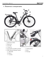
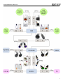
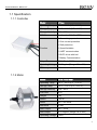
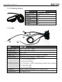
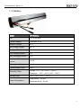
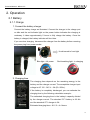
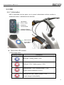
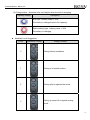
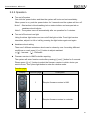
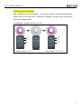
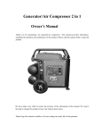
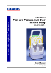
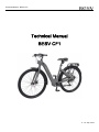
Technical Manual - BESV CF1 Technical Manual BESV CF1 V. 1.0, Sep. 2015 Technical Manual - BESV CF1 Contents 1. Electronic components ························································· 1 1.1 Specification ·············································································· 3 1.1.1 Controller ··························································································· 3 1.1.2 Motor ································································································· 3 1.1.3 Pedaling Sensor ················································································ 4 1.1.4 HMI ···································································································· 4 1.1.5 Battery ······························································································· 5 2. Operation ·············································································· 6 2.1 Battery ······················································································· 6 2.1.1 Charge ······························································································· 6 2.1.2 Important Safety Notes for Battery Charging ····································· 7 2.2 HMI ···························································································· 8 2.2.1 Information ························································································· 8 2.2.2 Operation ························································································· 10 3. Disassembling Components ··············································· 12 3.1 EMS (Electrical Manager System) ·········································· 12 3.2 Pedaling Sensor ······································································ 15 3.3 Motor ······················································································· 16 3.4 Switch ······················································································ 18 4. Trouble shooting ································································· 19 4.1 Error or warning alert······························································· 19 4.2 Basic ······················································································· 21 4.3 Advanced ················································································ 23 4.3.1 Battery ····························································································· 23 4.3.2 Motor ······························································································· 25 4.3.3 Whole Bike······················································································· 28 Technical Manual - BESV CF1 1. Electronic components 1 2 3 5 9 4 6 7 8 5 A 2 1 B C 6 7 3 9 1. HMI function button 2. Brake lever 4 3. Front light 4. Charge port 5. Power button and battery indicator 7. Pedaling sensor 6. EMS (Electrical Manager System) 8. Motor A. HMI PCBA 9. Rear light B. Battery C. Controller 1 Technical Manual - BESV CF1 2 Technical Manual - BESV CF1 1.1 Specification 1.1.1 Controller Model A-Type Operating Temp. -15°C ~ 50°C (5°F ~ 122°F) Storage Temp. -15°C ~ 100°C (5°F~ 212°F) Storage Humidity 10% ~ 85% ROHS Confirms the ROHS of PTC 1. Over voltage protection 2. Over current protection 3. Stall protection Function 4. Speed limitation 5. UART communication 6. BLDC driver with hall 7. Battery Communication Output Power 250W (Peak 380W) Operating Voltage 36V Regular (Range: 30 to 42V) Efficiency 92% Model 250W Front Gear Operating Temp. -15°C ~ 80°C (5°F ~ 176°F) Storage Temp. -15°C ~ 100°C (5°F ~ 212°F) Storage Humidity 10% ~ 90% Fork Size 36 H Weight 2 kg ROHS < 45 db Noise 120 ~ 450 RPM Max RPM 40 Nm Max Torque 180 ~ 300W Max Output 36 V Regular (Range: 24 to 48V) 1.1.2 Motor Operating Voltage > 80% 3 Technical Manual - BESV CF1 1.1.3 Pedaling Sensor Model Kingmeter RPM RPM Resolution 12 Impulses / Rotation Weight 43 g Operating Voltage 5 V Clockwise Yes Counterclockwise No Direction Yes 1.1.4 HMI 1 2 4 3 5 Model BESV HMI Operating Temp. -15°C ~ 70°C (5°F ~ 158°F) Storage Temp. -15°C ~ 80°C (5°F~ 176°F) Storage Humidity 20% ~ 80% Display Type Handlebar Switch and Power Button LED Indicator Lighting Control Integrated PWM Headlight + Taillight control 1 8 Pin Handlebar Switch 2 6 Pin Power Button I/O Cable Connector 3 6 Pin Power + UART communication cable to motor controller 4 2 Pin Rear Light 5 3 Pin Front Light Information Battery Capacity, Assistance Level, Version Query Assistant Level 3 Assistance Level 4 Technical Manual - BESV CF1 1.1.5 Battery Model CF1 Battery Cell LG - 2750 mAh Typical Capacity 7550 mAh ± 5% Nominal Voltage 37 V Max Charge Voltage 42.5 V Voltage at End Discharge 29.03 V Max. charging current 4A Max. Discharge current 12 A Continuous Discharge Current 10.8 A Capacity Led Display No Communication Type UART Operating Temp. Storage Temp. Power Consumption Charge:0°C ~ 40°C (32°F ~ 104°F) Discharge:-10°C ~ 40°C (14°F ~ 104°F) -20°C ~ 60°C (-4°F ~ 140°F) Sleep Mode:≦ 50mA Shutdown Mode:≦ 1mA 5 Technical Manual - BESV CF1 2. Operation 2.1 Battery 2.1.1 Charge 1. Connect the battery charger Connect the battery charge as illustrated. Connect the charger to the charge port on bike and the red indicator light on the power button indicates the charging is underway. It takes approximately 5 hours to fully charge the battery. Once the battery is charged, the battery indicator will turn blue. If you are done charging, disconnect the charger from the battery before removing the power plug from power socket. Hook toward to front light Blue light : full power Red-breathing light : in charging 2. Charging time The charging time depends on the remaining energy in the battery and the charger current. The acceptable charger input voltage is AC 100 - 240 V ~ 2A (50 / 60Hz). If the battery is completely discharged, you can estimate the charging time by the following calculation example: The estimated charging time is the battery’s capacity divided by the charger current. The standard CF1 battery is 8.8 Ah and the standard CF1 charger is 2A. Estimated charging time = 8.8 / 2 = 4.4 hours 6 Technical Manual - BESV CF1 2.1.2 Important Safety Notes for Battery Charging Use only the battery charger delivered with the product. Use only dry charger, undamaged power cable and charger. Replace damaged power cable and charger immediately. Remove any possible foreign object from the charging socket, such as dusts, ice or snow before plugging in. Using any battery charger other than the one delivered with the product may cause overheating of the batter y or even a risk of explosion. Deep discharging of battery may result in internal damage. There is a fire risk if the temperature of batter y rises up to a dangerous level. Avoid deep discharging of battery while in use or storage. If not in use, the battery should be charged fully at least every 3 months. Do not expose the bike in a storage temperature lower than -20°C (-4°F) or higher than 60°C (140°F). Please note that the internal structure of battery may be overheated to damage due to high temperature greater than 60°C, particularly exposed to direct sunlight. Do not use the charger at a humid place or an ambient temperature lower than -10°C (14°F) or higher than 40°C (104°F). The battery and charger are maintenance-free. Do not attempt to disassemble or modify the battery or charger. Do not expose the battery to high voltage. It is advised not use battery with damaged casing. Do not cover the battery or the charger while charging is in progress. 7 Technical Manual - BESV CF1 2.2 HMI 2.2.1 Information HMI is separated into two parts, one is power button/status indictor another is assistance button / assistance level indicator. Light Button (Front / Rear) Assistance Level Indicator Assistance Button (Increase / Decrease) Status Indictor Power Button (ON / OFF) Power button LED indicator (1) Discharge status Capacity Display Description Blue light : battery power > 50% Red light : 50% > battery power > 20% Red light flash : 20% > battery power > 10% Please change assistant to level 1. Red light fast flash : battery power < 10% Please charge it immediately. 8 Technical Manual - BESV CF1 (2) Charge status : Assistant level can’t adjust when the bike is charging. Capacity Display Description Blue light : battery power > 95% The battery is charged near to full capacity. Red-breathing light : battery power < 95% The battery is charging. Assistant Level Suggestion Level Assistance Display Riding condition 0 Riding without assistance. 1 Riding on a leveled surface. 2 Riding uphill or against the winds. 3 Riding up steep hill or against strong winds. 9 Technical Manual - BESV CF1 2.2.2 Operation Turn on/off system One click the power button and then the system will be turned on immediately. When power is on, push the power button for 3 seconds and the system will turn off. Note 1 : Start action is blue-breathing led on status indictor and marquee led on assistance level indictor. Note 2 : The system turns off automatically after no operation for 3 minutes. Turn on/off front and rear light Using front/rear light button can turn on/off the light on bike. Front light has two intensities, adjust it to full or half by pressing the light button again and again. Assistance level setting There are 3 different assistance levels can be chose by user. According different conditions on road, press [+] or [-] button to adjust assistant. ※ [+]:Increase [ -]:Decrease Firmware version in HMI\Controller requiring The system will enter function mode after pressing [+] and [-] button for 3 seconds. Please press [+] or [-] button to select the firmware version in which device you want to know. Then press light button to enter the relative mode. Function page Display Function page Description 1 Require firmware version in HMI. 2 Require firmware version in controller. 10 Technical Manual - BESV CF1 Firmware version information After entering "version information", the "status indicator" will keep flashing with purple color. At the same time, "assistance indicator" will show main version and sub version sequentially. For example : firmware version is 1.003 22 21 20 Main version : 20 = 1 22 21 20 Sub version : 20 + 21 = 3 11 Technical Manual - BESV CF1 3. Disassembling Components 3.1 EMS (Electrical Manager System) 1. Turn off the power and place the bike upside down. 2. Loosen the front light screw, take off the front light and then disconnect front light, charger and main cables. Charger cable Front light cable Main cable 3. Remove the right side wire cover carefully, pull out the switch connector and disconnect it. Press to unlock 12 Technical Manual - BESV CF1 4. Remove both side wire cover, push the power button holder up by finger. Then pull the button connector and disconnect it. Button holder 5. Loosen the bottom cover screw, and remove the bottom cover. And then disconnect motor, pedaling sensor and rear light cables. Rear light cable Motor cable Pedaling sensor cable 13 Technical Manual - BESV CF1 6. Lossen two battery screw. 7. Find the cable ties inside the down tube, hook the cable ties and then pull out the power kit very carefully. Check if any cable stuck during the whole procedure. 8. Power kit disassemble finished. Controller Battery HMI PCBA 14 Technical Manual - BESV CF1 3.2 Pedaling Sensor 1. Place the bike upside down, remove the bottom cover, and then disconnect pedaling sensor cable. Pedaling sensor cable 2. Loosen the left crank screw and then remove left crank. 3. Take apart the pedaling sensor with screw driver. 15 Technical Manual - BESV CF1 3.3 Motor 1. Place the bike upside down, remove the bottom cover, and then disconnect motor cable. Motor cable 2. Remove the both side rubber cap and the flange nut. 3. Shift the derailleur to the highest speed. 16 Technical Manual - BESV CF1 4. Bend the derailleur back and remove the rear wheel. 17 Technical Manual - BESV CF1 3.4 Switch 1. Remove the right side wire cover carefully, pull out the switch connector and disconnect it. Press to unlock 2. Loosen the screws on the switch and remove it. 18 Technical Manual - BESV CF1 4. Trouble shooting 4.1 Error or warning alert The system has some error or warning when user see the display of capacity show the blue and red led flash alternately. Error or warning can be decided by the assistance light flash automatically. If yes, it represents error and no assistant. If not, it represents warning. The following table shows the mean of this message. Warning message : Please press [light] and [-] button for 3 seconds. Then, hold two buttons to know the warning code. If you release this buttons, the e-bike can adjust assistance level as a normal status. Display Warning code Mean 1 G-Sensor Communication Fail 2 Battery Communication Fail 3 Battery Status Fail 19 Technical Manual - BESV CF1 Error message : Please recode the error code when you see the assistance light flash automatically. Display Error code Mean 1 The motor is stalled and unable to go forward. 2 The motor is driving hard. 3 The signal arrangement of hall sensors is wrong. 7 The connection between HMI and controller fails. 20 Technical Manual - BESV CF1 4.2 Basic Symptom possible Possible cause Consequence and solution Connect charger to charge port. The battery indicator will be red to show Battery is low. with authorized distributor. Instrument is not installed correctly, causing the electric connection to come loose. Battery indicator Malfunction of power system. flashing. The assistance If the battery indicator is red and blue alternative flash, please have a check System is not on. keeps blue/red charging is persisting. Incorrect version of program Check that the instrument, buttons, electric connectors on the handle bar, and the cables/wires around the motor and controller are connected correctly. Have an authorized distributor to check the bike. Have an authorized distributor upgrade the program. system isn't Interference between brake Adjust the brake system or find the consisting when and wheels. service of authorized distributor. pedaling. Tire pressure inappropriate or problematic. The assistance level goes back to 0 when pedaling. Poor connection between wire and controller. Motor is damaged. Inflate the tire or replace if it is flat. Reconnect or have an authorized distributor check the power controller system. Have an authorized distributor check the power controller system. If the battery indicator shows red fast Battery is low. charge if available. The lights are not working. flash or no light indicate, please go to Internal electric connection of lighting system comes loose or Have an authorized distributor check. abnormal in system. 21 Technical Manual - BESV CF1 Symptom possible Possible cause The battery may be poorly connected. The battery does not charge. Consequence and solution Make sure the batter y is connected correctly before repeating the charging cycle. The indicator on the charger is Have an authorized distributor to check not on. the charger. The battery is damaged. Have an authorized distributor to check the battery. Insert the brakes There is grease stain on the brake disc or shoes. If the brake disc or shoes are covered in grease, the braking distance will be longer and the risk of accident and Poor braking The brakes are not inserted. injury increases. When this happens, please go to an authorized distributor immediately. performance ‧ Clean the brake disc with alcohol. ‧ Change the brake shoes. ‧ Bring the dirty disc or shoes to an authorized distributor for examination. Poor braking performance and Bring the bike to an authorized distributor not distinctive braking action. to correct the leak. Worn brake shoes will lead to Metallic noises come out of brakes and it is rough to decelerate. longer braking distance and the risk of accident increases. When the brake shoes are worn beyond the minimum thickness, the shoe supports Have the brake shoes and brake disc, if necessary, changed by an authorized distributor. will grind into the friction ring on the brake disc. 22 Technical Manual - BESV CF1 4.3 Advanced 4.3.1 Battery The following progress is strongly recommended to be executed by technicians. Issue Step 1 Check step Action Check if the system turns on with procedure If yes, progress the next step. on user manual or not. If no, turn on the system. If yes, progress the next step. 2 Check if the connectors between battery and If no, tune off and then system connect steadily or not. reconnect the connectors steadily. 3 Unable to discharge Measure the output voltage and check the value is lower than 30V or not. If yes, please charge the battery. If no, progress the next step. Use the electronic thermometer to measure If yes, please stay the battery 4 4.1 the temperature of battery's surface, and as cool as room temperature. check if the value is larger than 68'c or not. If no, progress the next step. Open the battery case and check the fuse is broken or not. If yes, please replace with a new fuse. If no, progress the next step. If yes, please remove any 5 Open the battery case and get the circuit possible loading which causes board out, Check if there is short circuit on short circuit. output pin or not. If no, please contact with the manufacturer. 23 Technical Manual - BESV CF1 Issue Step Check step Action If yes, progress the next step. 1 Check if the connectors between battery and If no, tune off and then charger connect steadily or not. reconnect the connectors steadily. Use the electronic thermometer to measure If yes, please stay the battery 2 Unable to charge 2.1 the temperature of battery's surface, and as cool as room temperature. check if the value is larger than 68'c or not. If no, progress the next step. Open the battery case and check the fuse is broken or not. If yes, please replace with a new fuse. If no, progress the next step. If yes, please remove any 3 Open the battery case and get the circuit possible loading which causes board out, Check if there is short circuit on short circuit. output pin or not. If no, please contact with the manufacturer. 24 Technical Manual - BESV CF1 4.3.2 Motor Issue Step Check step Action If yes, please turn off the 1 Check if the connectors between motor and controller connect well or not. system and reconnect the motor's cable. If no, please progress the next step. If yes, please progress the next 2 Check the metal pins inside the connector of step. motor are bended or not. If no, please fix the metal pins or replace the connector. Unable to work 3 Check if the skin of connector and cable near axle is damaged, or core is exposed. Use meter to measure the signal of hall sensor (by 3 thin cables inside, yellow, blue, 4 green). With rotating the motor backwards manually, the voltage of signals should be 0V or 5V. If yes, please replace the cable. If no, please progress the next step. If yes, please progress the next step. If no, please replace the hall sensors and re-check again. If yes, please contact with the 5 Use meter to measure the resistance of hall manufacturer. sensor. Check if the value is infinite or not. If no, please replace the hall sensors and re-check again. No speed information Use meter to measure the resistance of 1 speed sensor. Check if the value is infinite or not. If yes, please contact with the manufacturer. If no, please replace the speed sensors and re-check again. 25 Technical Manual - BESV CF1 Issue Step Check step Action If yes, please turn off the 1 Check if the connectors between motor and controller connect well or not. system and reconnect the connectors. If no, please progress the next step. If yes, please progress the next 2 Check the metal pins inside the connector of step. motor are bended or not. If no, please fix the metal pins or replace the connector. If yes, please replace the 3 Check if the housing of motor is out of shape. Abnormal housing. If no, please progress the next step. vibration If yes, please replace the 4 Check if there is any abnormal noise from bearing. bearing while rotating the motor manually. If no, please progress the next step. 5 Check the axle of motor is rusty, or if there is any wiggle while rotating the motor manually. Use meter to measure the signal of hall sensor (by 3 thin cables inside, yellow, blue, 6 green). With rotating the motor backwards manually, the voltage of signals should be 0V or 5V. If yes, please replace the axle. If no, please progress the next step. If yes, please contact with the manufacturer. If no, please replace the hall sensors and re-check again. 26 Technical Manual - BESV CF1 Issue Step Check step Action If yes, please replace the 1 Use meter to check if the cable of motor is motor. short in circuit. If no, please progress the next step. The motion resistance is 2 If yes, please replace the criterion of inductance, and measure the motor. inductance with LRC meter, and then check If no, please progress the next if the value exceeds the criterion. heavier while motor is rotating. Please contact the manufacturer for the 3 Use scope to measure the EMF of motor and check if the signal is correct or not. Open the housing of motor, and use meter to 4 confirm any short circuit between silicon steel and any cable. step. If yes, please progress the next step. If no, please replace the motor. If yes, please replace the motor. If no, please contact with the manufacturer. 27 Technical Manual - BESV CF1 4.3.3 Whole Bike Issue Step Check step Action If yes, please adjust the 1 Check if the assistant level is 0 or not. assistant level >=1. If no, please progress the next step. If yes, please progress the next 2 Check if the connectors between motor and controller connect well or not. step. If no, please turn off the system and reconnect the motor's cable. If yes, please replace the 3 Use diagnosis tool to check the e-brake brake. signal without braking lever. If no, please progress the next step. No Connect the diagnosis tool to system. assistance Rotate the wheel backwards manually and If yes, please progress the step monitor the "U Hall", "V Hall", "W Hall". 6. All of the hall sensors shouldn't be ON or If no, please progress the next OFF at the same time, and should keep step. while pedaling. 4 changing while rotating. Replace the standard controller, and check 5 6 the result again after repeating the progress controller. of step 4. If no, please replace the motor. Connect the diagnosis tool to system. If yes, please contact with the Rotate the pedal forwards manually, and the manufacturer. "pedal 1" signal should keep changed, and If no, please progress the next "RPM" should show value. step. Replace the standard controller, and check 7 If yes, please replace the the result again after repeating the progress of step 6. If yes, please replace the controller. If no, please replace the pedaling sensor. 28 Technical Manual - BESV CF1 Issue Step Check step After turning on system, the HMI is on Replace the standard HMI and check the 1 normality again. but can't be Action If yes, please replace the HMI. If no, please replace the controller. operated If yes, please progress the next 1 Check if the connectors between motor and controller connect well or not. step. If yes, please turn off the system and reconnect the motor's cable. If yes, please replace the 2 motor. If no, please progress the next step. The Connect the diagnosis tool to system. assistance Rotate the wheel backwards manually and level resets to 0 while Check if there any damage in motor cable. 3 pedaling. monitor the "U Hall", "V Hall", "W Hall". All of the hall sensors shouldn't be ON or OFF at the same time, and should keep If yes, please progress the next step. If no, please replace the motor. changing while rotating. 4 Replace the standard motor and check the normality again. If yes, please progress the next step. If no, please replace the motor. If yes, please contact with the 5 Replace the standard controller and check manufacturer. the normality again. If no, please replace the controller. The HMI immediately turns off after turning on. 1 Replace the standard HMI and check the normality again. If yes, please replace the HMI If no, please contact with the manufacturer. 29 Technical Manual - BESV CF1 Issue Step Check step Connect the diagnosis tool to system. 1 Check the firmware version is correct or not. Connect the diagnosis tool to system. The assistance is 2 not smooth while firmware of controller. If yes, please progress the changed, and "RPM" should show value. next step. If yes, please replace the 3 Replace the standard controller and controller. check the normality again. If no, please replace the pedaling sensor. The initial value of "pedal sensor" should 4 be 0 or 1. Rotate the pedal forwards manually for 2 circles, and check if the "pedal signal" is 23 ~ 25 or not. Remove the battery. 1 Measure the voltage with meter and check it is lower than 30V or not. Charge the battery with charger and the 2 led indicator on charger should work normally. turned on or HMI can't be on. If no, please upgrade the If no, please progress the Connect the diagnosis tool to system. can't be next step. the "pedal 1" signal should keep pedaling. The system If yes, please progress the Rotate the pedal forwards manually, and step 4. and discontinuous Action If yes, please progress the next step. If no, please replace the pedaling sensor. If yes, please progress the next step. If no, please progress the step 3. If yes, please charge the battery fully then test again. If no, please replace the battery. If yes, please replace the 3 Replace the standard battery and check battery the normality again. If no, please progress the next step. 4 Replace the standard HMI and check the normality again. If yes, please replace the HMI If no, please contact with the manufacturer. 30 Technical Manual - BESV CF1 Issue Step Check step Connect the diagnosis tool to system. Power 1 Rotate the pedal backwards manually, and check if the "pedal signal" increase or not. outputs while pedaling backwards. Replace the standard controller, and check 2 the result again after repeating the progress of step 1. Action If yes, please contact with the manufacturer. If no, please replace the pedaling sensor. If yes, please replace the controller. If no, please replace the pedaling sensor. 31