1
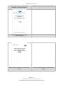
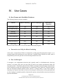
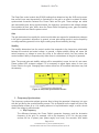
Section 10 - Grid Tie
Table of Contents
Warnings/Hazards
Reference Materials
Use Cases
Use Cases and Available Features
Connection to a Utility for Mains Paralleling
Part of a Microgrid
Stand-Alone Operation
Commissioning Procedure
PCU Configuration
Deep Sea Configurations
AVR Tuning
Configure DSE SCADA Settings
AVR Bias Tuning Procedure
Governor Bias Tuning Procedure
Dynamic Tuning for Grid Tie Operation
Frequency Synchronizer
Voltage Matcher
Load Share
Reactive Load Control
Configuration Screens
Target Power
Diagnostics
CT Polarity Diagnostics
Load Acceptance Test
Test PCU Shutdown Command
Troubleshooting
Page 10-2
770-00092 Section 10_Grid Tie (PP20/PP25) Rev A
770-00083 Power Pallet Technician's Handbook (PP20/v1.09) Rev B
Section 10 - Grid Tie
Brief Explanation of the Grid Tie System
The Power Pallet Grid Tie module uses a Deep Sea 8610 controller to synchronize the Power
Pallet with and export power to the grid. It is configurable through the Deep Sea Configuration
Suite Software with many settings also accessible through the controller interface. ALL Power
Labs ships the Power Pallet Grid Tie systems already configured. The settings should not be
changed unless done so by a trained professional.
1.
Warnings/Hazards
NOTE: Observe local regulations. Local codes may supersede these recommendations. Plan
your system with your utility company and an electrical engineer before connecting to the grid.
Be sure to read the DSE manuals and the manuals for the generator before attempting a grid
tie installation.
● Improperly connecting the Power Pallet to an electrical system can cause electrical
current from the generator to backfeed into the utility grid or microgrid when it should
be shut down. This backfed power could unexpectedly electrocute utility workers or
other individuals who come into contact with wires or electrical equipment, or cause the
generator to explode or catch fire. It is imperative that you consult the utility company or
a qualified electrician in order to determine the additional equipment that will be required
to safely interconnect to the utility grid or microgrid.
● Disconnect the electrical system from the grid before carrying out maintenance or
repairs on the grid tie system.
● There is risk of danger to equipment if the equipment is in mains paralleling mode
and ‘stand-alone mode’ is enabled. In this case, the system will close to dead bus and
thus will energize the grid causing risk danger to equipment and operator or linemen.
● Improper connections to an electrical system can allow electrical current from the
generator to backfeed into the utility lines. Such backfeed may electrocute utility
company workers or others who contact the lines during a power outage, and the
generator may explode, burn, or cause fires when utility power is restored. Consult the
utility company or a qualified electrician.
● Always disconnect system from the grid before servicing. Do not work on equipment
when powered.
Page 10-3
770-00092 Section 10_Grid Tie (PP20/PP25) Rev A
770-00083 Power Pallet Technician's Handbook (PP20/v1.09) Rev B
Section 10 - Grid Tie
III.
Reference Materials
Deep Sea Electronics has a full listing of manuals and quick start guides available in several
languages on their website available for download. Please visit:
http://www.deepseaplc.com/support/product-software/dse-genset/synchronising-load-sharingcontrollers/dse8610.
This document may occasionally refer you to one of the following technical manuals.
DSE8610 Quick Start Guide
DSE8610 Control Module (User Manual)
Page 10-4
770-00092 Section 10_Grid Tie (PP20/PP25) Rev A
770-00083 Power Pallet Technician's Handbook (PP20/v1.09) Rev B
Section 10 - Grid Tie
DSE Configuration Suite PC Software
Installation & Operation Manual
DSE8600 Configuration Suite Software Manual
Load Share System Design and
Commissioning
Guide to Synchronising and Load Sharing
Part 1
Guide to Synchronising and Load Sharing
Part 2
Page 10-5
770-00092 Section 10_Grid Tie (PP20/PP25) Rev A
770-00083 Power Pallet Technician's Handbook (PP20/v1.09) Rev B
Section 10 - Grid Tie
IV.
Use Cases
A. Use Cases and Available Features
The following features sets are available:
Feature
Mains Paralleling
Part of a Microgrid
Stand Alone
Operation
Fixed export control
Yes
Yes
No
No Break transfer
N/A
No
N/A
Islanding
No
No
No
Load sharing
No
No
No
Close to dead bus
No
No
Yes
Earth fault detection
No
No
No
Mains decoupling
Yes*
No
N/A
Vector Shift
Yes
No
N/A
*Does not meet IEEE 1547, CEI not met (Mains Decoupling triggers)
a. Connection to a Utility for Mains Paralleling
In this case, a single Power Pallet is connected to a utility grid with fixed power export––i.e. a
constant power level that does not vary with load. If multiple Power Pallets are onsite, each is
independently tied to the grid with no load sharing between the units.
b. Part of a Microgrid
A microgrid is an independent electrical grid, typically small- or distributed-scale, that may
connect to a larger utility grid, but can meet its power and control requirements within the
microgrid system.. Because a grid-tied Power Pallet is configured for fixed export, the generator
will not respond to match the load demand as a standalone Power Pallet will. Therefore, ensure
that the microgrid includes another power source or storage ability. If the Power Pallet is
exporting more power than there is load on the microgrid, excess power will be generated with
no sink, leading to unstable operation, high reactive power, and potentially overcurrent electrical
trips and shutdowns.
Page 10-6
770-00092 Section 10_Grid Tie (PP20/PP25) Rev A
770-00083 Power Pallet Technician's Handbook (PP20/v1.09) Rev B
Section 10 - Grid Tie
If there is more load on the microgrid than the Power Pallet is exporting and there is no other
power source that can support excess load, the Power Pallet’s generator will bog down and an
underfrequency or under-voltage electrical trip alarm is likely to occur.
An example of this is a diesel generator and Power Pallet supplying load to the microgrid.
c. Stand-Alone Operation
Note: ALL Power Labs does not support stand-alone operation of the Power Pallet Grid-Tied
models. However, instructions are provided for troubleshooting purposes only that are only to
be done by an APL certified technician.
In order to enable this feature connect battery ground on main negative bus inside enclosure
to digital input D (DSE pin 63). Contact APL support before carrying out any changes related to
standalone operation.
Page 10-7
770-00092 Section 10_Grid Tie (PP20/PP25) Rev A
770-00083 Power Pallet Technician's Handbook (PP20/v1.09) Rev B
Section 10 - Grid Tie
V.
Commissioning Procedure
Please note that the Grid Tie Power Pallets are already configured when shipped. The
commissioning procedure listed here is offered for reference only.
1. PCU Configuration
Enable ‘Grid Tie’ mode on the PCU. Navigate to the view for this configuration setting by using
the buttons on the control panel.
2. Deep Sea Configurations
The APL Grid Tie Configuration Worksheet is available in the Documentation and Resources
package on the USB key that is sent with each system as a resource to calculate the
configurations needed for site specific needs. Please contact [email protected] for
this if needed.
APL Configuration Worksheet inputs:
1. Configuration (generator)
a. frequency
b. generator wiring
2. Nominal voltage
3. Upper and Lower mains disconnect values (if different than IEEE 1547 defaults)
a. frequency
b. voltage
Once the input values have been entered into the worksheet, use the output values in the
lowest section of the spreadsheet to configure your DSE controller. To do this, the “Deep
Sea Configuration Suite PC Software” must be installed on your computer, which you can
download from the Deep Sea Electronics website after creating a free user account (http://
www.deepseaplc.com/home/). You should enter the worksheet’s output values into the base
file* (which is provided by APL and includes other base configurations for the Power Pallet)
using the DSE Configuration Suite software. Upload the modified config file to DSE from the
DSE configuration program over a USB connection. Please consult the DSE 8600 Configuration
Suite Software Manual for upload instructions. Note: if the DSE 8610 module firmware version is
different than the DSE base configuration file version, you must reconcile the two by upgrading
or downgrading the configuration file or the module firmware.
If the configuration of the system is changed from its original configuration when shipped,
APL customer service representative must be notified to ensure future service and warranty
coverage.
If you are re-configuring your Power Pallet or grid tie system, you should download the original
DSE configuration file from the Deep Sea module and save it on your computer, in addition to
saving a version of the new DSE configuration file.
*Please contact APL Customer Service for the base file.
Page 10-8
770-00092 Section 10_Grid Tie (PP20/PP25) Rev A
770-00083 Power Pallet Technician's Handbook (PP20/v1.09) Rev B
Section 10 - Grid Tie
3. AVR Tuning
a. Disconnect the two (orange and black) bias wires on the generator’s AVR
(automatic voltage regulator). See wiring diagram.
b. Make sure that the tiny arrow on the AVR VOLT potentiometer is centered within
the tick marks.
c. The arrow on the STAB potentiometer should be set two marks clockwise from
the, fully-counterclockwise position.
d. Start the engine. Wait until “Generator Available” appears on the DSE controller
screen.
e. Adjust the VOLT potentiometer to change the phase to phase (Ph-Ph) voltage to
the desired nominal voltage, as displayed on the DSE controller screen.
Page 10-9
770-00092 Section 10_Grid Tie (PP20/PP25) Rev A
770-00083 Power Pallet Technician's Handbook (PP20/v1.09) Rev B
Section 10 - Grid Tie
Figure x. Location of VOLT and STAB potentiometer on generator AVR.
4. Configure DSE SCADA Settings
The following procedure is designed to confirm that the DSE is able to accurately control genset
output voltage (through the AVR) and the frequency (controlled by the governor) via the DSE
program’s supervisory control and data acquisition (SCADA) interface. To set the SCADA
settings most easily, connect your computer to the USB port on the DSE controller and connect
to the module using the Deep Sea 8600-series Configuration Suite. For further reading, please
see page 15 in the Deep Sea Commissioning Load Share System Design Manual.
IMPORTANT: The SCADA settings must be set independently after the configuration
file is uploaded to the DSE module because they are not stored as a part of the module
configuration file. This feature also permits the DSE controller to carry out real-time monitoring
and control through SCADA, without the need to re-upload configuration files. The Clone
Module feature transfers both the configuration AND the settings of the Multiset, Governor/
AVR interface and the Sync page. For more information see DSE 8600 Config SW Manual.
The DSE module controls the governor and AVR on the genset through bias voltages, which
command them to increase or decrease the output frequency and voltage, respectively. The
bias voltages are configured through setting the bias “center” voltage ( SW1), and range ( SW2).
Figure 1. Illustration of the center and range of the bias voltages for the AVR and
governor.
The following procedures confirm that the Deep Sea has control of the genset voltage and
frequency.
Page 10-10
770-00092 Section 10_Grid Tie (PP20/PP25) Rev A
770-00083 Power Pallet Technician's Handbook (PP20/v1.09) Rev B
Section 10 - Grid Tie
A. AVR Bias Tuning Procedure
CAUTION: For bias voltages exceeding 2.5V, the AVR’s default behavior is to reject
the bias input. This can lead to unexpected behavior of the generator. For more
information, consult the AVR manual.
CAUTION: Bias voltages outside the range of -5V to +5V may damage the AVR. The
Deep Sea can output voltages from 0-10V.
●
●
●
●
voltage.
●
●
●
●
Initial AVR SW1 = See Value In Configurations Table
Initial AVR SW2 = See Value In Configurations Table
Record initial SW1 value (SW1i)
With genset running - Adjust SW1 to raise the output frequency 15% over nominal
○
For example: 230V Ph-Ph * 115% = 265V (230V + 35V) (see Table 1)
The generator should be kept running without load
Record the value of SW1 (SW1f)
Set SW2 to the difference between SW1f - SW1i
Set SW1 to the initial value (SW1i)
Table 1. Nominal and Upper phase-to-phase voltage examples
Nom. V Ph-Ph
Upper V Span (115% of Nom.)
190
219
200
230
208
239
220
253
230
265
240
276
254
292
266
306
277
319
380
437
400
460
415
477
440
506
460
529
480
552
Page 10-11
770-00092 Section 10_Grid Tie (PP20/PP25) Rev A
770-00083 Power Pallet Technician's Handbook (PP20/v1.09) Rev B
Section 10 - Grid Tie
B. Governor Bias Tuning Procedure
●
●
●
●
●
●
●
●
●
Disconnect governor bias wires from back of DSE controller
Initial Governor SW1 = See Value In Configurations Table
Initial Governor SW2 = See Value In Configurations Table
The generator should be kept running without load
Record initial SW1 value (SW1i)
With genset running - Adjust SW1 to raise the output frequency by 2.5Hz (SW1f)
Record the final value of SW1 (SW1f)
Set SW2 to the difference between SW1f-SW1i
Set SW1 to the initial value (SW1i)
Editing Parameters:
All settings can be configured using the Configuration Suite software. Do not alter these
settings unless recommended by a trained APL certified technician. Most settings can also be
configured through the DSE control panel: Press and hold the (√) button for basic settings. For
advanced settings press and hold (√) and (STOP) buttons.
For more information see: DSE8610 Control & Instrumentation System Operators Manual
- 9. FRONT PANEL CONFIGURATION
Page 10-12
770-00092 Section 10_Grid Tie (PP20/PP25) Rev A
770-00083 Power Pallet Technician's Handbook (PP20/v1.09) Rev B
Section 10 - Grid Tie
VI. Dynamic
Operation
Tuning
for
Grid
Tie
Each utility grid or microgrid has unique dynamics and the Power Pallet’s generator must be
“tuned” to properly synchronize and maintain stable power export.
The figure below shows the hardware configuration of the Deep Sea Module and the Power
Pallet:
Figure x. Control Scheme of the Power Pallet and Deep Sea Module
Figure x. Control dynamic response in relation to gain and stability values
Figure 3. Dynamic system responses according to gain/stability parameters.
State
Available
Sync
On Grid
Governor
No Bias
Frequency Match
Load Share Control
Generator
Field
No Bias
Voltage Match
Reactive Power Control
Page 10-13
770-00092 Section 10_Grid Tie (PP20/PP25) Rev A
770-00083 Power Pallet Technician's Handbook (PP20/v1.09) Rev B
Section 10 - Grid Tie
The Deep Sea control module has SCADA settings that determine how the AVR and governor
bias control loops react dynamically to fluctuations in the grid in an effort to maintain a stable,
synchronized connection between the Power Pallet and the grid. These settings are called
gain and stability and, during synchronization, the frequency synchronizer and voltage matcher
are controlled by their gain, while, when the Power Pallet is exporting power, gain and stability
control load share and reactive power control.
Gain
The gain determines how rapidly the control module bias can respond to instantaneous changes
in the grid or generator’s dynamics. In general, a lower gain setting results in a slow frequency
or voltage matching process, but too high a setting may cause instability (hunting).
Stability
The stability determines how the control module bias responds to the longer-term relationship
between the nominal and actual voltage. In general, a higher stability setting will cause the
actual frequency or voltage to come very close to the nominal values, but may reduce the
control module’s ability to respond quickly when there is a disturbance in the grid or generator.
Note: The pre-set gain and stability settings will be acceptable in some, but not all, use cases.
Please contact APL customer support if it is necessary to adjust these values to tune your
Power Pallet to the grid. Changing these values without an APL-certified technician may void
the warranty.
Figure 4. Deep Sea synchronizer screen
1. Frequency Synchronizer
The frequency synchronizer adjusts governor bias to bring the generator’s frequency into sync
with the grid during the synchronization process. This is displayed on the upper left side of the
synchronization screen as a +/-Hz reading when out of synchronization range, or with a check
mark if the voltage is within bounds.
● Slip Frequency
The difference between the Power Pallet’s generator frequency and the bus/mains
frequency of the grid. For example, with a slip frequency of 0.2 Hz, the two power
sources will be in phase (zero phase angle) once every five seconds. With stable
Page 10-14
770-00092 Section 10_Grid Tie (PP20/PP25) Rev A
770-00083 Power Pallet Technician's Handbook (PP20/v1.09) Rev B
Section 10 - Grid Tie
generator frequency, the bar will consistently move to the right across the screen, while
frequency variation will show as inconsistent movement back and forth across the
screen.
2. Voltage Matcher
During the synchronization process,the voltage matcher adjusts the AVR bias in order to
synchronize the generator’s voltage to that of the grid. This is displayed on the upper right side
of the synchronization screen as a +/-V reading when out of synchronization range, or with a
check mark if the voltage is within bounds.
When both the frequency and voltage of the Power Pallet’s generator are synchronized with
those of the grid, the bar will move into the zero phase angle window and be bounded by
vertical bars. At this time, you should hear a loud click, which is the contactor closing the circuit
and creating a connection between the generator and the grid.
3. Load Share
When the Power Pallet is connected to the grid, the load share control adjusts the governor
bias. Because the generator is locked in synchronization with the grid when the contactor is
closed, the speed change request effectively is a request to open or close the governor throttle.
Thus, the load share effectively controls the amount of real power export from the system based
on the configurable target power setpoint.
4. Reactive Load Control
When the Power Pallet is connected to the grid,the reactive load control controls the AVR
bias . Since the generator voltage is locked in synchronization with the grid when the contactor
is closed, the voltage change request effectively is a request to increase or decrease the
generator field, adjusting the ratio between reactive power for the amount of real power.
Note: Reactive load control is typically unstable under 5 kW of real power.
VII. Configuration Screens
[image of configuration screen]
The DSE control module has a series of monitoring and configuration screens. In order to switch
between different information topics in the monitoring screens, use the left and right arrow
buttons. In order to see different status screens within each topic area, use the up and down
arrow buttons. The “Status” screen is important, as it displays the status of the generator, such
as “Generator at Rest”, “Generator Available”, and “On Load”. Once the Power Pallet is on load,
the most useful monitoring screens are under the “Generator” heading. Simply press up once
Page 10-15
770-00092 Section 10_Grid Tie (PP20/PP25) Rev A
770-00083 Power Pallet Technician's Handbook (PP20/v1.09) Rev B
Section 10 - Grid Tie
to see the targets for various critical variables, such as load level, reactive power, power factor,
and biases displayed as percentages and up once more to see their absolute values.
● Target Power
The Power Pallet target power output for fixed export can be adjusted through the SCADA
settings in the DSE Configuration Suite software, under Multiset ->Load Levels ->Maximum.
It can also be adjusted on the Deep Sea control module interface by adjusting “Load Parallel
Power” - see “editing parameters”
(Note: Minimum load level is the point at which the contactor will open when ramping off load.
We recommend maintaining the preset value in order to prevent contactor arcing)
Other important values, such as the power factor, can also be adjusted in the Configuration
Suite under Multiset within SCADA settings or through the DSE control module interface. For
complete instructions, please see________(manuals).
VIII. Diagnostics
A. CT Polarity Diagnostics
See 8610 User Manual sections 3.5.2 and 3.5.3 for more information on the CT Polarity
Diagnostics method.
B. Load Acceptance Test
●
Load acceptance test - load system to 50% of power rating and confirm stable
operation.
●
During this load test, confirm current transformers are reading correct power [kW]
and PF (e.g. ~1 for resistive loads)
●
Engine should accept and shed load with stable recovery to nominal speed and
voltage (e.g. within a maximum of 10 seconds)
C. Test PCU Shutdown Command
●
●
●
●
Enter PCU Test menu
Scroll to FET3 Starter
Turn on
The DSE control module should raise an alarm that says “PCU Commanded Shutdown”
Page 10-16
770-00092 Section 10_Grid Tie (PP20/PP25) Rev A
770-00083 Power Pallet Technician's Handbook (PP20/v1.09) Rev B
Section 10 - Grid Tie
IX.
Troubleshooting
The troubleshooting provided in this table is only for a trained APL technician only or if directed
by a trained APL technician or APL support team. Please do not conduct any troubleshooting
below before contacting APL support.
Symptom
Possible Root Cause
System Does not Parallel to Miswiring or loose wiring.
Bus/Grid
Solution
Check that the DSE
Input/Output pins and the
enclosure’s internal wiring are
correct
PCU shutdown alarm not DSE Input/Output pins may Test PCU Shutdown
shutting down Deep Sea
not be properly configured
Command. Check that wiring
from PCU, inside enclosure,
and at DSE controller is
correct and connected.
Synchronizing system does
not export power and causes
“Reverse Power” alarm
Mains Paralleling mode may
not be enabled.
Check that Mains Paralleling
mode is enabled. Shipped
configuration: Input D is left
“open” = Mains Paralleling
active
AVR bias rapidly fluctuating
while on grid
Incorrect reactive power
control tunings
Adjust reactive power control
after consulting APL support
Symptom?
AVR bias out of range
Adjust AVR SW1/2
Fluctuating amperage or
power factor despite stable
governor
Poor reactive power control
Adjust reactive power control
settings
Unstable power export
Poor load share control
Adjust load share settings
“Fail to sync” alarm
Unstable frequency
Check gas quality, governor
stability, clean governor
Contactor not operating
correctly
Possible miswire of solenoid
voltage wiring
Check wiring
Negative power values
reported.
CT(s) reversed polarity
Flip CTs to correct polarity
Page 10-17
770-00092 Section 10_Grid Tie (PP20/PP25) Rev A
770-00083 Power Pallet Technician's Handbook (PP20/v1.09) Rev B
Section 10 - Grid Tie
Over-voltage
Incorrect DSE wire-topology Incorrect AVR potentiometer
settings
setting or bias
Under-voltage
Incorrect DSE wire-topology
settings
“E-stop alarm”
Ignition circuit fuse blown
Replace fuse (#3?)
“E-stop alarm”
Bad wiring
Confirm wiring
Unexpected engine shutdown
Outside pre-set parameters
Operate with in pre-set
parameters or change
parameters.
Unexpected engine shutdown
E-stop pressed
Reset E-stop button
Unexpected engine shutdown
PCU commanded shutdown
Check PCU alarm and refer
to Automation Assembly
section of APL Technician’s
Handbook
*See provided DSE 8610 User Manual Section 11 and the DSE 8600 Series Configuration Suite
Software Manual Section 4.5.3 for expanded troubleshooting
Page 10-18
770-00092 Section 10_Grid Tie (PP20/PP25) Rev A
770-00083 Power Pallet Technician's Handbook (PP20/v1.09) Rev B