1
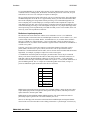
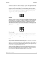
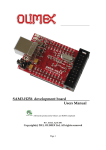
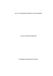
EM406 GPS-UAV
Development Platform
Version 2.9
Hardware description
Hardware
05/25/2009
EM406 GPS-UAV
Development
Platform Version 2.9
The red UAV DevBoard version 2.9 is the replacement for Bill Premerlani’s green UAV
DevBoard, which is no longer available. When Analog Devices discontinued the ADXRS401
gyros, Bill and SparkFun decided to revise his UAV development board to use the LISY300AL
gyroscopes instead of the ADXRS401. The new “red” board has the following advantages over the
previous “green” one:
•
The LISY300AL has 4 times the dynamic range of the ADXRS401, so the new “red”
board is capable of 4 times faster turning rate without saturating the gyros.
•
The design of the new “red” board has the accelerometers, the gyros, and the A/D
reference voltage all operating ratiometrically and tied to a single regulated 3.3 volt
power supply. This completely eliminates variations in the 5 volt supply to the board as a
source of accelerometer and gyro drift.
Bill has revised all of his testing, demo, and flight firmware, available at
http://www.diydrones.com/page/uav-devboard, to be able to work with either the previous “green”
board or the new “red” one. Each firmware zip file contains two projects, a green one for the
previous board, and a red one for the new board.
Hardware
Also refer to the schematic, available at SparkFun, to see how the hardware is connected to the
CPU.
EM406 SiRF III GPS receiver
The heart of the GPS-UAV is the GPS receiver. The EM406 SiRF III is more than adequate for
determining location and direction of motion. Complete specifications are available either on the
manufacturer’s website or at Spark Fun.
The EM406 initializes very quickly, so it does not have provision for a backup battery. It does
have an internal “supercap” that will save settings for several days. After that the EM406 reverts
to factory settings, including 4,800 baud, NMEA, for the communications protocol.
Once per second the GPS reports information useful for navigation including longitude, latitude,
altitude, and direction and speed over ground. Vertical speed is available via the binary interface.
The direction and speed information from the GPS is much more accurate than what you could
compute by subtracting successive pairs of positions, since it is based on a Doppler shift
calculation using the baseband signal.
The location information is generally more accurate than advertised by the manufacturer.
Furthermore, if you use the GPS-UAV to simply fly around your flying field, you can improve the
accuracy somewhat by navigating in terms of motion relative to a GPS measured reference point,
such as the location of your plane when you turn it on.
EM406 UAV v2.9 5/25/09
2
Hardware
5/25/2009
Communications with the GPS is either with a NMEA standard format or a binary format.
There are two USARTs in the dsPIC30F4011. The communications link between the GPS receiver
and the CPU is via TX and RX pins of USART number 2. The board includes a MOSFET
transistor to shift the 2.8 volt output of the EM406 up to the 5 volts needed by the input of the
CPU. Pin assignments on the CPU are:
From GPS to CPU
RX2/RF4
From CPU to GPS
TX2/RF5
The default baud rate of the EM406 is 4,800 and the default protocol is NMEA, which is quite
readable. It is suggested that you purchase Spark Fun’s ET-312 evaluation board or something
similar to become familiar with the SiRF binary and NMEA protocols.
The GPS LED will flash when the GPS is ready. However:
Be careful in setting the reporting rates of the various output messages. In some of the
past versions of the SiRFIII, the flashing of the GPS LED was controlled by toggling the
LED each time a certain message goes out. If you suppress that message, the GPS status
LED may stop flashing. Also, the GPS status LED will stop flashing in the binary
communications protocol.
Also, do not use the binary protocol at 4,800 baud, it results in a 10 second latency,
apparently because of a flaw in the buffer flushing logic. If you are using the binary
protocol, use 19,200 baud or higher.
Information about the EM406 is available on the Spark Fun website, www.sparkfun.com, or on
the manufacturer’s website, www.usglobalsat.com.
Antenna
The antenna is built into the EM406.
Proper operation of the GPS depends only broadly on the orientation of the antenna. For best
results, orient the plane of the antenna parallel to the ground. Other than that, the GPS does not
require any particular orientation of the antenna. As the antenna moves through space the GPS
indicates where it is and its vector velocity.
dsPIC30F4011
The CPU is a Microchip dsPIC30F4011. Manuals are available from Microchip at
www.microchip.com. The dsPIC30F4011is ideally suited for use in a three axis GPS-UAV, with
plenty of processing power and features, including:
•
16 bit architecture, with 40 bit accumulators.
•
C compiler available from Microchip. (There is both a free compiler and a purchased
compiler. The optimization features that are included with the purchased compiler
become disabled in the free compiler after a month, but they are really not needed for
adequate performance of the controller.) There is a great deal of support for the
dsPIC30F4011 built into the compiler, including an extensive runtime library. Especially
impressive is the smooth and efficient way the vector and matrix routines in the library
map onto the hardware.
•
Clock speed up to 120 MHz.
EM406 UAV v2.9 5/25/09
3
Hardware
05/25/2009
•
Two USARTS. One of them is connected to the GPS, the other can be used for
debugging.
•
Vectored, prioritized interrupts simplify interrupt processing. Each interrupt source is
matched to a dedicated service routine for just that resource. Each source can be assigned
one of seven levels of interrupt priority.
•
Free running PWM generator makes it possible to control 3 servos after initial setup by
simply writing to three 16 bit duty cycle registers.
•
Free running buffered A/D converter samples 7 analog input channels and generates an
interrupt when a set of samples is ready.
•
16 bit capture inputs measure the pulse widths of the 4 radio channels and generates a
separate interrupt for each channel.
•
Mapping of program space into data space. The combination of the dsPIC architecture
and the support provided by the C compiler makes it easy to construct lookup tables.
Oscillator
The CPU can be run at 8, 16, 32, 64, or 120 MHz. There are two high speed options to clock the
CPU. There is a 16 MHz crystal mounted on the board that runs in the oscillator in the HS (high
speed) mode. Also, the CPU has a built in fast RC, adjustable 7.5 MHz oscillator that can be used
with or without a 4X, 8X frequency multiplier, and which can be run with a 16X frequency
multiplier for a top speed of 120 MHz.
Gyros and 3 axis accelerometer
There are three STMicroelectronics LISY300AL gyros, one for each axis, and a three axis
MMA7260 accelerometer from Freescale. Sensitivity of the gyros is approximately 3.3 millivolts
per degree per second, with a maximum range of plus or minus 300 degrees/second. Sensitivity of
the accelerometers, which are set on the 6 g range, is approximately 200 millivolts per g, with a
maximum range of plus or minus 6 g. Specifications for the gyros and accelerometers are available
on the STMicroelectronics website, www.st.com, on the Freescale website, www.freescale.com
and on the Spark Fun website, www.sparkfun.com.
The previous version of the board had much narrower dynamic ranges for the accelerometers and
the gyros. That was done deliberately to improve immunity to drift. At the time the board was
designed, the author was not yet aware of the direction-cosine-matrix algorithm, (DCM) which
completely compensates for gyro drift. With the DCM firmware, the previous board has excellent
performance, so it was decided to extend the dynamic range of the new board. Tests on the new
board using the DCM firmware show that it is possible to achieve both wide dynamic range and
good accuracy at the same time.
The direction of each axis is marked on the board as X, Y, and Z. The accelerometer is mounted
on the top of the board under one of the gyros, with the directions indicated by the manufacturer
aligned with the X, Y, and Z markings. Similarly, the axis of the X, Y, and Z gyros are aligned
with the markings on the board. For each axis, the accelerometer measures acceleration along that
axis, and the gyro measures rotation around that axis. For the accelerometer, refer to the
manufacturer’s data sheet for the definition of positive and negative acceleration. The gyros
produce positive change in output voltage when they are rotated in the direction indicated on their
breakout boards. Keep in mind that the gyros measure rotation rates in the reference frame of the
plane, not the reference frame of the ground.
Also note that it is not precisely true that the accelerometers measure acceleration. What each
accelerometer actually measures is the gravity minus acceleration, so when the plane is not
accelerating, each accelerometer measures the component of gravity along its measurement axis.
EM406 UAV v2.9 5/25/09
4
Hardware
5/25/2009
The sign convention used by the manufacturer to label the positive reference direction is such that
the output is actually equal to gravity minus acceleration. For example, the Z axis points down.
With the board resting level with the components on top, the output of the Z accelerometer is
positive with respect to its baseline reference voltage. Accelerating the board down in the positive
Z direction reduces the output voltage.
The outputs of the gyros and accelerometers are analog voltages. Zero rotation and zero
acceleration correspond approximately to half voltage. Gyro supply voltages, accelerometer
supply voltage, and the analog-to-digital converter reference voltage are all tied to an onboard
regulated 3.3 volt supply. The gyros, accelerometers, and A/D are all ratiometric, so effects of
variations in the 5 volt main supply to the board are totally eliminated.
The motionless output voltages of the gyros and accelerometers varies from unit to unit. It is
recommended that you self-zero them by taking their output voltages at power up as baselines.
The best way to do this is to initialize your filters to the first sample, run the filters for at least 10
seconds, and then take the filtered values as the baselines.
The gyros can drift slightly with temperature. It was decided not to provide a temperature
measurement for temperature compensation. It is recommended that you use the DCM algorithm
to convert gyro and accelerometer signals into attitude information. The DCM algorithm will
completely compensate for gyro drift with temperature, so no temperature compensation is
needed.
The analog signals from the gyros and accelerometers are read on the following A/D channels of
the dsPIC30F4011 (note that the gyros are not in sequential order):
XRATE
AN2/RB2
YRATE
AN3/RB3
ZRATE
AN1/RB1
3.3 volts
AN0/RB0
XACCEL
AN6/RB6
YACCEL
AN7/RB7
ZACCEL
AN8/RB8
In order to get the full benefit of the ratiometric behavior of the gyro and accelerometer
outputs, you must use the 3.3 volt regulator supply voltage as the positive reference for
the A/D converter. The 3.3 volt supply is connected to pin AN0/RB0/AREF+ pin of the
dsPIC30F4011. When setting the A/D configuration, select the AN0/RB0/AREF+ pin as
the positive reference voltage for the conversion.
Filtering and sampling rate
The accelerometers and gyros have built in analog first order RC low pass filters for noise
reduction and anti-aliasing. However, their corner frequencies are not low enough to prevent
aliasing. It is recommended that you over-sample, digital filter, and decimate. Because of the 5
kHz vibration frequency of the gyros, you should sample around 5,000 samples per second per
channel. The dsPIC30F4011 is easily capable of that sampling rate.
EM406 UAV v2.9 5/25/09
5
Hardware
05/25/2009
It is recommended that you set up the A/D converter in a free running mode to lower processing
overhead. In the free running mode, the hardware automatically does most of the work, all your
software has to do is save sets of samples in response to interrupts.
The gyro and accelerometer signals will feed into your servo control processing. Since the highest
recommended update rate to the servos is approximately 40 Hz, you will want a decimation filter
between the sampling processing and the control processing. The recommended approach is to
select a sampling rate of 5,000 samples per second per channel and to implement a simple first
order digital low pass filter with a corner frequency somewhere between 40 Hz and 400 Hz as part
of the A/D interrupt processing. Let the filter update its output for every sample and simply let the
control processing read it asynchronously as needed. Provided you use 16 bit variables, there will
not be any issues with asynchronous read/write.
Radio/servo input/output pulses
The interface between the GPS-UAV and the servos and the RC receiver is via 7 PWM I/O
connection points on the board. There are 4 PWM inputs from the RC receiver labeled 1, 2, 3, and
4 on the board, collectively labeled “Radio”, and indicated as I1, I2, I3 and I4 on the schematic.
There are 3 PWM servo outputs labeled 1, 2, and 3 on the board, collectively labeled “Servos”,
and indicated as O1, O2, and O3 on the schematic. Signals on these connections are standard RC 5
volt TTL servo pulses.
Typically, you will use 3 inputs and 3 outputs to control three channels of the plane, such as
power, rudder, and elevator, or power, aileron, and elevator. The 4th input from the radio is
intended as a command channel from the radio, such as selection between manual and autonomous
flight mode, for example, or perhaps to adjust one or more control gains.
5 volt PWM I/O connection points are through 3 pin male headers. Servos may be connected
directly to the board. Connection to the radio are made using cables with female connectors on
both ends. Labels on the board indicate which rows of pins are ground, + 5 volts, and signal.
Ground is nearest the edge of the board, the middle row of pins is + 5 volts, and the inboard row of
pins are PWM signal I/O. The +5 volt pins are connected together on the board, serving as a
power bus. PWM I/O signal connections to the CPU are as follows:
I1
IC7/RB4
I2
IC8/RB5
I3
IC2/OC2/RD1
I4
IC1/OC1/RD0
O1
PWMH1/RE1
O2
PWMH2/RE3
O3
PWMH3/RE5
PWM inputs are through interrupt-on-change pins. The dsPIC30F4011 makes the interface rather
simple. Each input pin can be assigned its own separate interrupt routine, and each pin can use a
capture function to measure pulse width.
PWM outputs are through dsPIC30F4011 PWM generators. The 16 bit architecture makes it
particularly simple to generate the waveforms needed by the servos.
There is no direct physical connection on the board between PWM inputs and outputs. Manual
control of the servos from the radio can be reliably performed as a “pass-through” in software, by
EM406 UAV v2.9 5/25/09
6
Hardware
5/25/2009
assigning a high priority level to the input pins, and keeping the manual control software very
simple.
The GPS-UAV can control three servos. If you are using additional servos, you can still use them
in conjunction with the GPS-UAV by making a direct connection between the radio and the extra
servos. This is also a useful debugging technique. For example, while you are debugging one axis
of the control you can provide manual control for the other axis with a direct connection between
radio and servo.
Signals are standard servo pulses, with a pulse width of between 1 millisecond and 2 milliseconds,
and approximately 25 milliseconds between pulses. Between pulses, the signal level is a TTL low,
and the pulse is a TTL high. Of course, you can measure the characteristics of your own RC radio
using the GPS-UAV.
Be careful in designing the duty cycle of pulses for controlling the servos. The
approximately 25 millisecond delay between pulses is deliberate, and is a result of the
way that the original designers of RC radios used time multiplexing to control several
servos over a single radio channel. As a result, there is a “pulse stretcher” within the
servos. If you eliminate the delay, or significantly reduce it, the pulse stretchers in the
servos will misoperate as well as create a short on the power supply.
You can use the PWM controllers in the dsPIC30F4011 in a simple-minded fashion to create a
continuous stream of properly spaced pulses. Simply use the period to establish the spacing
between pulses, and the duty cycle equal to control the pulse widths.
Be careful in your firmware with gains and/or filtering to make sure that there is not excessive
servo “chatter”, which will result in excessive servo currents and heating.
ICSP header
The GPS-UAV includes an ICSP header which is used for programming and debugging. If you
use the MPLAB compatible ICD2 from Spark Fun, simply connect the cable that comes with it
directly between the ICD2 and the GPS-UAV. If you use something else, you may need to use an
adapter. Spark Fun sells an adapter between ICSP and RJ12.
It is not recommended that you try to power the GPS-UAV from the ICD2.
Pin assignments on the ICSP header are as follows. Facing the connector from the edge of the
board, pin 1 is on the left, closest to the reset button.
1
VPP
2
VCC
3
GND
4
PGD
5
PGC
6
N/C
LEDS
In addition to the LED built into the GPS that flashes to indicate valid data, the board has two
surface mounted LEDs, a red one and a green one, indicated as Stat1 and Stat2 on the board. I am
EM406 UAV v2.9 5/25/09
7
Hardware
05/25/2009
not going out on a limb to say which one is which color, its best to simply light them both up and
see. The LEDs are connected from the CPU output pins to plus 5 volts through a resistor, so you
will need to set the pins to zero to light them up.
The LEDs are useful for debugging. However, it is recommended that when you are ready for
flight, you should mount the board inside your aircraft, in which case you will not be able to see
the LEDs. Once you have your firmware debugged, you can signal status by deflecting the control
surfaces. For example, while the board is zeroing the gyros and waiting for the GPS, it could
“waggle” the rudder, and then stop when the process is complete.
Stat1
RF0
Stat2
RF1
Switches
Three switches connected between pull up resistors and ground are provided for setting options,
debugging, or operation, or whatever you like. They are labeled SR1, SR2 and SR3 with the idea
that in the final version of your software, you might use them as servo reversing switches. They
were not used during the development of the first prototype, all options were set in software
during debugging. Note that three switches are not enough to describe all combinations of board
orientations and servo directions. If you decide to use the switches for servo reversing, it is
suggested that you select a single preferred board orientation, or account for board orientation in
your firmware.
SR1
RD3
SR2
RD2
SR3
RF6
Size and weight
Board size is 1.5 inches wide by 2.75 inches long by 1 inch high, and will fit quite nicely inside
almost any airframe. The separate GPS radio/antenna is 1.125 inches by 1.125 inches by .375
inches high. For the gyros and accelerometers to work properly, the board must be attached firmly
to the plane. One convenient mounting approach is with Velcro.
The total weight of the board and radio/antenna is approximately 1 ounce.
Power
There is no separate connection on the board for an external power supply. Power for the board is
always backfed from the connections to the servo/radio pins.
There are two on-board voltage regulators, one to provide 5 volts to the CPU, GPS, and LEDs, the
other to provide 3.3 volts to the accelerometer and gyros. The board provides signal voltage level
shifting from the GPS to the CPU. Although the GPS accepts a 5 volt power supply, its TX output
is only 2.8 volts, not enough for the RX input of the CPU.
Only the power for the CPU, gyros, accelerometers and GPS flows through the main 5 volt
regulator, approximately 100 milliamps. The power for the radio and the servos flows directly to
them without going through the regulator. Total current load on a 4.8 volt battery for the board,
three servos, and an RC radio is about 150 milliamps when the servos are steady.
EM406 UAV v2.9 5/25/09
8
Hardware
5/25/2009
The positive voltage of the servo connection, pin 2, of all 7 of the servo/radio connectors are all
tied together and feed the input of the 5 volt regulator. The most common way to distribute power
during operation is to provide 5 volts directly to the radio and to backfeed the board via the cables
between the board and the radio. Power for the servos then flows directly to the servos from the
servo bus on the board, while power for the board passes through its voltage regulator. Everything
also works out if you are using the battery eliminator function of a motor speed control, regardless
of whether the 3 wire cable for the speed control is connected to the radio or to the board.
During testing and debugging, supply power to the board on any of the power pins of the
servo/radio connectors.
The board works well with a 4.8 volt NiCad even when the battery is nearly completely
discharged. It also works with a 5 volt battery eliminator circuit of a speed control. In principle, it
should work with a battery voltage up to 7.4 volts, but it has never been tested above 5 volts.
The issue with a supply voltage much greater than 5 volts is not so much the power dissipation of
the on board voltage regulator, but rather the voltage shifts for the signals among the board, radio,
and servos. The board will be operating at 5 volts, while the servos and radio will be operating at
the supply voltage. Signals from the radio to the board will be fine, because of the resistors in
series with the input pins, but the 5 volts output from the board to the servos might not be high
enough to operate the servos, depending on the design of the particular servos that you are using,
and the amount that the supply exceeds 5 volts.
The board has not been tested with a direct connection to Lithium Polymer batteries, so you are on
your own if you want to go with LiPo, but here are some considerations: The use of a single cell
LiPo to power the board will probably not work, because the board has been observed to stop
working when a 4.8 NiCad gets near the limit of its normal discharge range. The use of a two cell
LiPo will apply approximately 7.4 volts to the radio and servos, which exceeds the rating of many
commonly used products, and will cause a control voltage level shift between the radio, servos,
and CPU I/O pins, which will be running at 5 volts. If you want to use LiPo, you would probably
do well to use 2 cells and a battery eliminator circuit to drop down to 5 volts. You can try a two
cell LiPo directly to the board and see if it works, it is not likely to burn out the voltage regulator.
If you decide to use a power supply during debugging it is recommended to supply
the board with 5 volts. You can use a voltage supply that is higher than that, but
be careful not to exceed the power dissipation limits of the 5 volt regulator.
Assuming a 25 degree C ambient, the 5 volt regulator is capable of dissipating 420 milliwatts. The
total current through the regulator is the sum of the CPU, GPS, gyro, and accelerometer currents.
The CPU current depends on the selected clocking option. The following table gives the load
current and maximum allowable supply voltage as a function of clocking option.
Clocking option
Supply current
Maximum supply
Fast RC
80 mA
10.2 V
16 MHz crystal
90 mA
9.6 V
Fast RC X 4
100 mA
9.2 V
Fast RC X 8
130 mA
8.2 V
Fast RC X 16
180 mA
7.4 V
EM406 UAV v2.9 5/25/09
9
Hardware
05/25/2009
Spare pins
The board also provides access to the unused CPU pins: 4 digital I/Os and a spare USART,
(USART1). For most applications you will not need them, but if you find some use for them, they
work and are labeled at the edge of the board:
GND
ground
RXI
U1ARX/RC14
TXO
U1ATX/RC13
VCC
Regulated 5 V
RE8
RE8
RE0
RE0
RE2
RE2
RE4
RE4
Note that since the default pins for USART1 are used by the board for other functions, if you want
to use USART1, when you set up its control registers, you will need to assign the use of its
alternate pins for RX and TX, as shown in the table. Also note that VCC is on the load side of the
5 volt regulator. Finally, note that all spare pins are directly connected, without any series
resistors, so be careful.
Recommended accessories
In addition to the GPS-UAV, there are several items that you may want to buy from Spark Fun:
•
MPLAB Compatible ICD2 with USB and RS232. This item is highly recommended. You
will need something to program the CPU, and this is a good choice. An
assembler/linker/debugger software tool is available for free from Microchip that will be
sufficient for firmware development. There is also a very good C compiler from
Microchip that is highly recommended. There is both a free version and a purchased
version. The free version disables access to some optimizations a month after installation,
but none of them are critical.
•
ET312 SiRFIII Evaluation Kit. This is an entirely optional item. You can get by without
it, but having it may save some development time by allowing you to play around with
the NMEA interface through your computer.
•
EM406 GPS radio/antenna. This is the GPS radio that connects to the board, sold
separately by Spark Fun. If you have an application that requires a GPS radio, buy it,
otherwise the board will function just fine as an IMU without a GPS radio.
•
12 inch GPS cable. The cable that comes with the GPS is only about one inch long.
SparkFun also sells 12 inch cables, which will give you more flexibility in mounting the
GPS. They sell a lot of them, and are sometimes out of stock.
•
12 inch female-to-female servo cables. You will need female-female servo cables to
connect your board to your receiver.
EM406 UAV v2.9 5/25/09
10